Page 3948 of 4647
HARNESS
PG-97
C
D
E
F
G
H
I
J
L
MA
B
PG
Revision: 2007 April2007 M35/M45
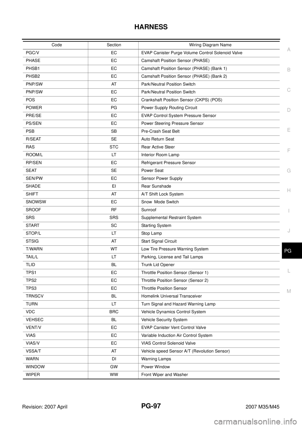
PGC/V EC EVAP Canister Purge Volume Control Solenoid Valve
PHASE EC Camshaft Position Sensor (PHASE)
PHSB1 EC Camshaft Position Sensor (PHASE) (Bank 1)
PHSB2 EC Camshaft Position Sensor (PHASE) (Bank 2)
PNP/SW AT Park/Neutral Position Switch
PNP/SW EC Park/Neutral Position Switch
POS EC Crankshaft Position Sensor (CKPS) (POS)
POWER PG Power Supply Routing Circuit
PRE/SE EC EVAP Control System Pressure Sensor
PS/SEN EC Power Steering Pressure Sensor
PSB SB Pre-Crash Seat Belt
R/SEAT SE Auto Return Seat
RAS STC Rear Active Steer
ROOM/L LT Interior Room Lamp
RP/SEN EC Refrigerant Pressure Sensor
SEAT SE Power Seat
SEN/PW EC Sensor Power Supply
SHADE EI Rear Sunshade
SHIFT AT A/T Shift Lock System
SNOWSW EC Snow Mode Switch
SROOF RF Sunroof
SRS SRS Supplemental Restraint System
START SC Starting System
STOP/L LT Stop Lamp
STSIG AT Start Signal Circuit
T/WARN WT Low Tire Pressure Warning System
TAIL/L LT Parking, License and Tail Lamps
TLID BL Trunk Lid Opener
TPS1 EC Throttle Position Sensor (Sensor 1)
TPS2 EC Throttle Position Sensor (Sensor 2)
TPS3 EC Throttle Position Sensor
TRNSCV BL Homelink Universal Transceiver
TURN LT Turn Signal and Hazard Warning Lamp
VDC BRC Vehicle Dynamics Control System
VEHSEC BL Vehicle Security System
VENT/V EC EVAP Canister Vent Control Valve
VIAS EC Variable Induction Air Control System
VIAS/V EC VIAS Control Solenoid Valve
VSSA/T AT Vehicle speed Sensor A/T (Revolution Sensor)
WARN DI Warning Lamps
WINDOW GW Power Window
WIPER WW Front Wiper and Washer Code Section Wiring Diagram Name
Page 3974 of 4647
REAR PROPELLER SHAFT
PR-7
C
E
F
G
H
I
J
K
L
MA
B
PR
Revision: 2007 April2007 M35/M45
ComponentsNDS000EE
VQ35DE 2WD MODELS (3S80A-1VL107 TYPE)
VK45DE 2WD MODELS (3F-R-2VL107 TYPE)
PDIA0964E
1. Propeller shaft (1st shaft) 2. Center flange 3. Center bearing mounting bracket
(Lower)
4. Floor reinforcement 5. Center bearing assembly 6. Propeller shaft (2nd shaft)
7. Clip 8. Center bearing mounting bracket
(Upper)9. Washer
10. Lock nut
A: Both side
B: For the tightening torque, refer to PR-12, "
ASSEMBLY" .
Refer to GI-11, "
Components" , for the symbols in the figure.
PDIA0965E
1. Propeller shaft (1st shaft) 2. Center bearing mounting bracket
(Lower)3. Floor reinforcement
4. Propeller shaft (2nd shaft) 5. Clip 6. Center bearing mounting bracket
(Upper)
Refer to GI-11, "
Components" , for the symbols in the figure.
Page 3975 of 4647
PR-8
REAR PROPELLER SHAFT
Revision: 2007 April2007 M35/M45
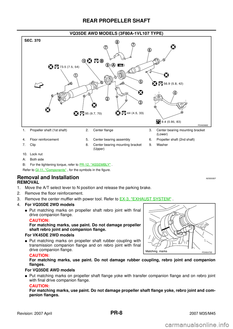
VQ35DE AWD MODELS (3F80A-1VL107 TYPE)
Removal and InstallationNDS000EF
REMOVAL
1. Move the A/T select lever to N position and release the parking brake.
2. Remove the floor reinforcement.
3. Remove the center muffler with power tool. Refer to EX-3, "
EXHAUST SYSTEM" .
4.For VQ35DE 2WD models
�Put matching marks on propeller shaft rebro joint with final
drive companion flange.
CAUTION:
For matching marks, use paint. Do not damage propeller
shaft rebro joint and companion flange.
For VK45DE 2WD models
�Put matching marks on propeller shaft rubber coupling with
transmission companion flange and on rebro joint with final
drive companion flange.
CAUTION:
For matching marks, use paint. Do not damage rubber coupling, rebro joint and companion
flanges.
For VQ35DE AWD models
�Put matching marks on propeller shaft flange yoke with transfer companion flange and on rebro joint
with final drive companion flange.
CAUTION:
For matching marks, use paint. Do not damage propeller shaft flange yoke, rebro joint and com-
panion flanges.
PDIA0966E
1. Propeller shaft (1st shaft) 2. Center flange 3. Center bearing mounting bracket
(Lower)
4. Floor reinforcement 5. Center bearing assembly 6. Propeller shaft (2nd shaft)
7. Clip 8. Center bearing mounting bracket
(Upper)9. Washer
10. Lock nut
A: Both side
B: For the tightening torque, refer to PR-12, "
ASSEMBLY" .
Refer to GI-11, "
Components" , for the symbols in the figure.
PDIA0470E
Page 3977 of 4647
PR-10
REAR PROPELLER SHAFT
Revision: 2007 April2007 M35/M45
INSTALLATION
Note the following, and install in the reverse order of removal.
CAUTION:
Avoid damaging the rebro joint boot, protect it with a shop towel or equivalent.
�Align matching marks to install propeller shaft to final drive and transfer (AWD models only) companion
flanges, and then tighten to specified torque. Refer to PR-7, "
Components" .
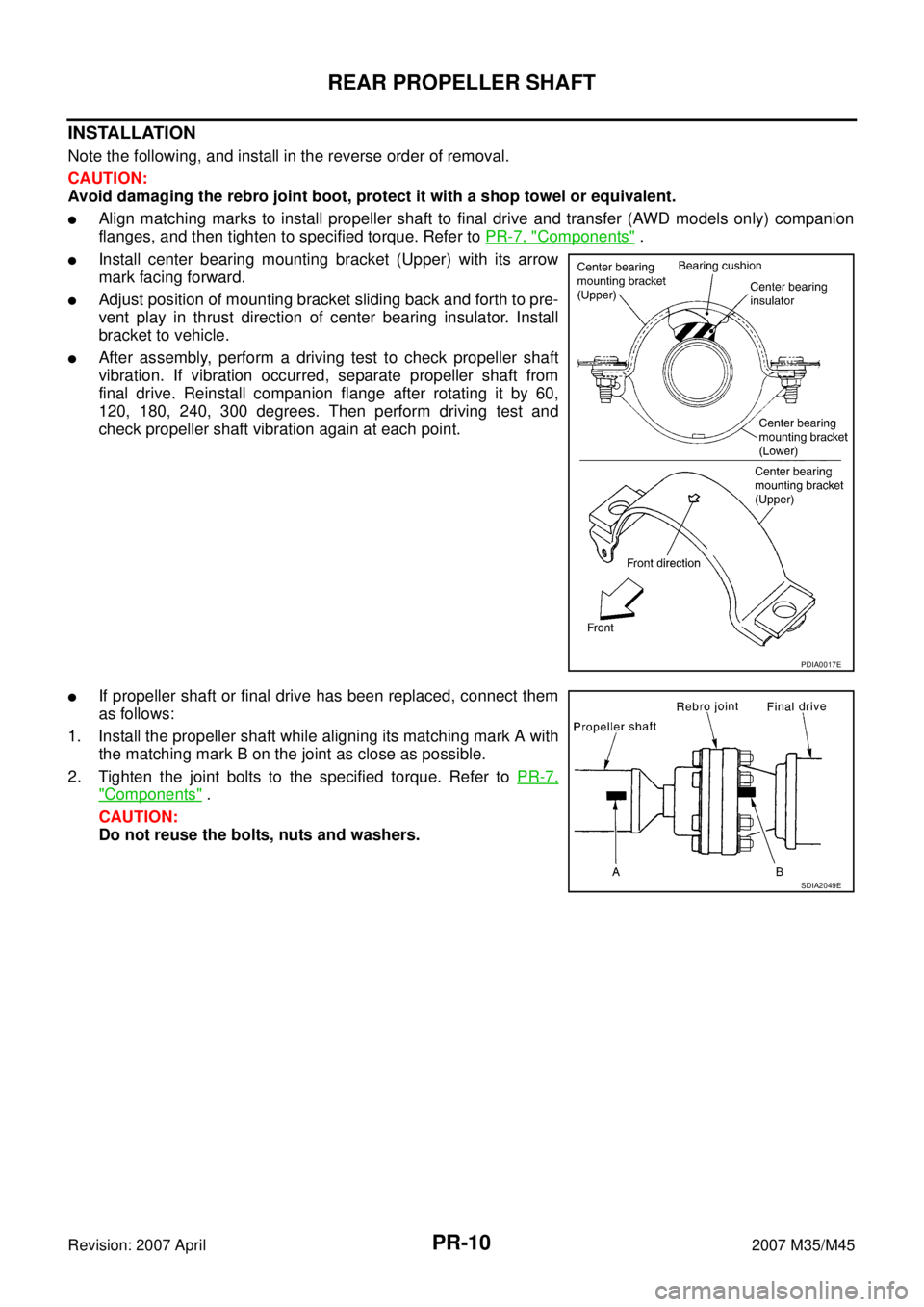
�Install center bearing mounting bracket (Upper) with its arrow
mark facing forward.
�Adjust position of mounting bracket sliding back and forth to pre-
vent play in thrust direction of center bearing insulator. Install
bracket to vehicle.
�After assembly, perform a driving test to check propeller shaft
vibration. If vibration occurred, separate propeller shaft from
final drive. Reinstall companion flange after rotating it by 60,
120, 180, 240, 300 degrees. Then perform driving test and
check propeller shaft vibration again at each point.
�If propeller shaft or final drive has been replaced, connect them
as follows:
1. Install the propeller shaft while aligning its matching mark A with
the matching mark B on the joint as close as possible.
2. Tighten the joint bolts to the specified torque. Refer to PR-7,
"Components" .
CAUTION:
Do not reuse the bolts, nuts and washers.
PDIA0017E
SDIA2049E
Page 3978 of 4647
REAR PROPELLER SHAFT
PR-11
C
E
F
G
H
I
J
K
L
MA
B
PR
Revision: 2007 April2007 M35/M45
Disassembly and Assembly of Center Bearing (For 3S80A-1VL107 and 3F80A-
1VL107 Type)
NDS000EG
DISASSEMBLY
1. Put matching marks on propeller shaft and center flange, then
disassemble the 1st and 2nd propeller shaft.
CAUTION:
For matching marks, use paint. Do not damage the propel-
ler shaft flange and center flange.
2. Put matching marks onto the center flange and propeller shaft
end as shown.
CAUTION:
For matching marks, use paint. Do not damage propeller
shaft end and center flange.
3. Hold the center flange using the flange wrench, and remove the
lock nut.
4. Remove the center flange using a commercial available bearing
puller then remove washer.
5. Press out the center bearing using the puller and hydraulic
press.
SDIA1538E
SDIA1539E
Tool number : KV40104000 ( — )
SDIA1540E
Tool number : ST30031000 (J-22912-01)
SDIA1541E
Page 3979 of 4647
PR-12
REAR PROPELLER SHAFT
Revision: 2007 April2007 M35/M45
ASSEMBLY
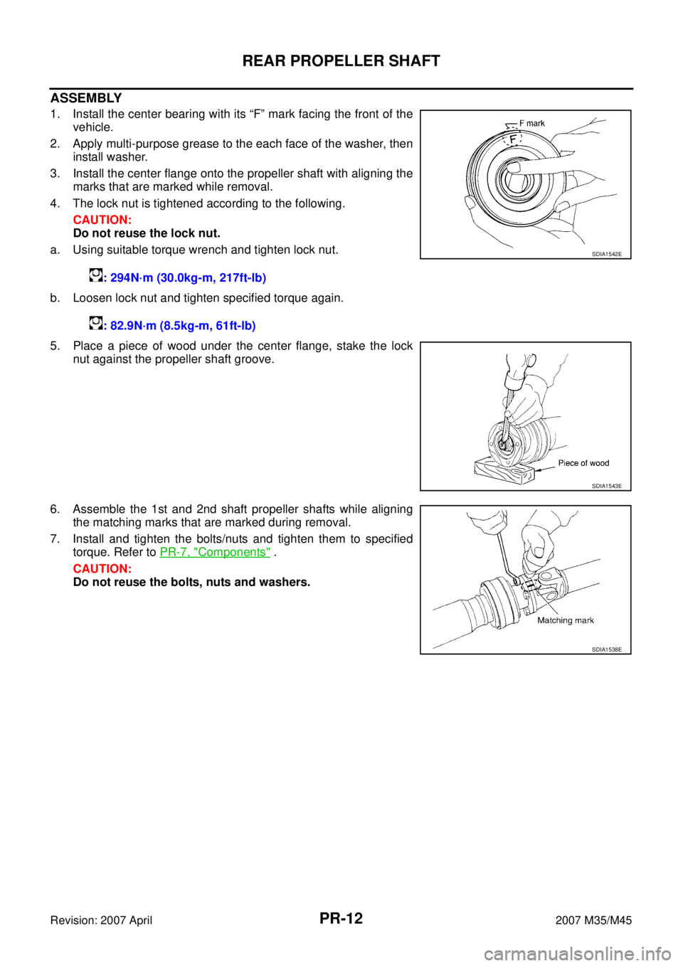
1. Install the center bearing with its “F” mark facing the front of the
vehicle.
2. Apply multi-purpose grease to the each face of the washer, then
install washer.
3. Install the center flange onto the propeller shaft with aligning the
marks that are marked while removal.
4. The lock nut is tightened according to the following.
CAUTION:
Do not reuse the lock nut.
a. Using suitable torque wrench and tighten lock nut.
b. Loosen lock nut and tighten specified torque again.
5. Place a piece of wood under the center flange, stake the lock
nut against the propeller shaft groove.
6. Assemble the 1st and 2nd shaft propeller shafts while aligning
the matching marks that are marked during removal.
7. Install and tighten the bolts/nuts and tighten them to specified
torque. Refer to PR-7, "
Components" .
CAUTION:
Do not reuse the bolts, nuts and washers.: 294N·m (30.0kg-m, 217ft-lb)
: 82.9N·m (8.5kg-m, 61ft-lb)
SDIA1542E
SDIA1543E
SDIA1538E
Page 3989 of 4647
PS-8
POWER STEERING FLUID
Revision: 2007 April2007 M35/M45
POWER STEERING FLUIDPFP:KLF20
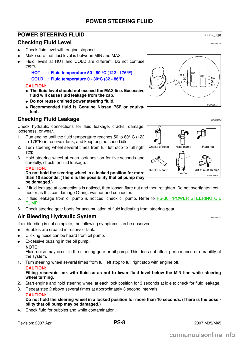
Checking Fluid LevelNGS000D5
�Check fluid level with engine stopped.
�Make sure that fluid level is between MIN and MAX.
�Fluid levels at HOT and COLD are different. Do not confuse
them.
CAUTION:
�The fluid level should not exceed the MAX line. Excessive
fluid will cause fluid leakage from the cap.
�Do not reuse drained power steering fluid.
�Recommended fluid is Genuine Nissan PSF or equiva-
lent.
Checking Fluid LeakageNGS000D6
Check hydraulic connections for fluid leakage, cracks, damage,
looseness, or wear.
1. Run engine until the fluid temperature reaches 50 to 80° C (122
to 176°F) in reservoir tank, and keep engine speed idle.
2. Turn steering wheel several times from full left stop to full right
stop.
3. Hold steering wheel at each lock position for five seconds and
carefully, check for fluid leakage.
CAUTION:
Do not hold the steering wheel in a locked position for more
than 10 seconds. (There is the possibility that oil pump may
be damaged.)
4. If fluid leakage at connections is noticed, then loosen flare nut and then retighten. Do not overtighten con-
nector as this can damage O-ring, washer and connector.
5. If fluid leakage from oil pump is noticed, check oil pump. Refer to PS-30, "
POWER STEERING OIL
PUMP" .
6. Check steering gear boots for accumulation of fluid indicating from steering gear.
Air Bleeding Hydraulic SystemNGS000D7
If air bleeding is not complete, the following symptoms can be observed.
�Bubbles are created in reservoir tank.
�Clicking noise can be heard from oil pump.
�Excessive buzzing in the oil pump.
NOTE:
Fluid noise may occur in the steering gear or oil pump. This does not affect performance or durability of
the system.
1. Turn steering wheel several times from full left stop to full right stop with engine off.
CAUTION:
Filling reservoir tank with fluid so as not to lower fluid level below the MIN line while steering
wheel turning.
2. Start engine and hold steering wheel at each lock position for 3 seconds at idle to check for fluid leakage.
3. Repeat step 2 above several times at approximately 3 second intervals.
CAUTION:
Do not hold the steering wheel in a locked position for more than 10 seconds. (There is the possi-
bility that oil pump may be damaged.)
4. Check fluid for bubbles and while contamination.HOT : Fluid temperature 50 - 80 °C (122 - 176°F)
COLD : Fluid temperature 0 - 30°C (32 - 86°F)
PGIA0007J
SGIA0506E
Page 4012 of 4647
POWER STEERING OIL PUMP
PS-31
C
D
E
F
H
I
J
K
L
MA
B
PS
Revision: 2007 April2007 M35/M45
Disassembly and Assembly (Models with VK45DE)NGS000DG
COMPONENTS
INSPECTION BEFORE DISASSEMBLY
Disassemble oil pump only when the following malfunctions occur.
�If oil leakage is found on oil pump.
�Oil pump pulley is damaged or deformed.
�Performance of oil pump is low.
1. Pulley 2. Snap ring 3. Drive shaft
4. Joint 5. O-ring 6. Connector bolt
7. Flow control valve 8. Spring 9. Oil seal
10. Suction pipe 11. O-ring 12. Body assembly
13. O-ring 14. Side plate 15. Vane
16. Rotor 17. Cam ring 18. Cartridge
19. Dowel pin 20. Gasket 21. Rear cover
22. Copper washer
Refer to GI-11, "
Components" , and the followings for the symbols in the figure.
: Apply power steering fluid.
: Apply multi-purpose grease.
SGIA1187E