Page 4087 of 4647

RFD-18
REAR FINAL DRIVE ASSEMBLY
Revision: 2007 April2007 M35/M45
Disassembly and AssemblyNDS000F8
COMPONENTS
1. Drive pinion lock nut 2. Companion flange 3. Front oil seal
4. Pinion front bearing 5. Gear carrier 6. Side oil seal
7. Side flange 8. Collapsible spacer 9. Pinion rear bearing
10. Pinion height adjusting washer 11. Drive pinion 12. Side bearing adjusting washer
13. Side bearing 14. Side gear thrust washer 15. Circular clip
16. Side gear 17. Lock pin 18. Pinion mate gear
19. Pinion mate thrust washer 20. Pinion mate shaft 21. Drive gear
22. Differential case 23. Bearing cap 24. Filler plug
25. Gasket 26. Rear cover 27. Drain plug
A: Oil seal lip
B: Screw hole
C: After tightening the bolts to the specified torque, tighten the bolts additionally by turning the bolts 31 to 36 degrees.
Refer to GI-11, "
Components" and the followings for the symbols in the figure.
:Apply gear oil.
:Apply anti-corrosion oil.
:Apply Genuine Silicone RTV or equivalent. Refer to GI-47, "
Recommended Chemical Products and Sealants" .
:Apply Genuine High Strength Thread Locking Sealant or equivalent. Refer to GI-47, "
Recommended Chemical Prod-
ucts and Sealants" .
PDIA0986E
Page 4088 of 4647

REAR FINAL DRIVE ASSEMBLY
RFD-19
C
E
F
G
H
I
J
K
L
MA
B
RFD
Revision: 2007 April2007 M35/M45
ASSEMBLY INSPECTION AND ADJUSTMENT
�Before inspection and adjustment, drain gear oil.
Total Preload Torque
1. Secure final drive assembly onto an attachment.
2. Remove side flanges.
3. Rotate drive pinion back and forth 2 to 3 times to check for unusual noise and rotation malfunction.
4. Rotate drive pinion at least 20 times to check for smooth opera-
tion of the bearing.
5. Measure total preload with the preload gauge.
NOTE:
Total preload torque = Pinion bearing preload torque + Side
bearing preload torque
�If measured value is out of the specification, disassemble it to
check and adjust each part. Adjust the pinion bearing preload and side bearing preload.
Adjust the pinion bearing preload first, then adjust the side bearing preload.
Drive Gear Runout
1. Remove rear cover. Refer to RFD-22, "Differential Assembly" .
2. Fit a dial indicator to the drive gear back face.
3. Rotate the drive gear to measure runout.
�If the runout is outside of the repair limit, check drive gear
assembly condition; foreign material may be caught between
drive gear and differential case, or differential case or drive gear
may be deformed, etc.
CAUTION:
Replace drive gear and drive pinion gear as a set.Tool number A: KV38100800 (J-25604-01)
Tool number A: ST3127S000 (J-25765-A)
Total preload torque:
2.84 - 3.75 N·m (0.29 - 0.38 kg-m, 26 - 33 in-lb)
PDIA0766J
When the preload torque is large
On pinion bearings: Replace the collapsible spacer.
On side bearings: Use thinner side bearing adjusting washers by the same amount to
each side. Refer to RFD-38, "
Side Bearing Adjusting Washer" .
When the preload is small
On pinion bearings: Tighten the drive pinion lock nut.
On side bearings: Use thicker side bearing adjusting washers by the same amount to
each side. Refer to RFD-38, "
Side Bearing Adjusting Washer" .
Runout limit: 0.05 mm (0.0020 in)
SPD886
Page 4090 of 4647

REAR FINAL DRIVE ASSEMBLY
RFD-21
C
E
F
G
H
I
J
K
L
MA
B
RFD
Revision: 2007 April2007 M35/M45
4. If tooth contact is improperly adjusted, follow the procedure
below to adjust the pinion height (dimension X).
�If the tooth contact is near the face (face contact), or near the
heel (heel contact), thicken pinion height adjusting washers to
move drive pinion closer to drive gear.
Refer to RFD-38, "
Pinion Height Adjusting Washer" .
�If the tooth contact is near the flank (flank contact), or near the
toe (toe contact), thin pinion height adjusting washers to move
drive pinion farther from drive gear.
Refer to RFD-38, "
Pinion Height Adjusting Washer" .
Backlash
1. Remove rear cover. Refer to RFD-22, "Differential Assembly" .
2. Fit a dial indicator to the drive gear face to measure the back-
lash.
�If the backlash is outside of the specified value, change the
thickness of side bearing adjusting washer.
CAUTION:
Do not change the total amount of washers as it will change the bearing preload.
SDIA0517E
PDIA0440E
PDIA0441E
Backlash: 0.10 - 0.15 mm (0.0039 - 0.0059 in)
When the backlash is large:
Make drive gear back side adjusting washer thicker,
and drive gear tooth side adjusting washer thinner by
the same amount. Refer to RFD-38, "
Side Bearing
Adjusting Washer" .
When the backlash is small:
Make drive gear back side adjusting washer thinner,
and drive gear tooth side adjusting washer thicker by
the same amount. Refer to RFD-38, "
Side Bearing
Adjusting Washer" .
SPD513
Page 4092 of 4647
REAR FINAL DRIVE ASSEMBLY
RFD-23
C
E
F
G
H
I
J
K
L
MA
B
RFD
Revision: 2007 April2007 M35/M45
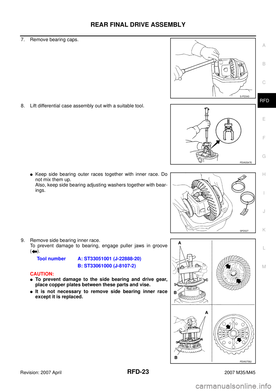
7. Remove bearing caps.
8. Lift differential case assembly out with a suitable tool.
�Keep side bearing outer races together with inner race. Do
not mix them up.
Also, keep side bearing adjusting washers together with bear-
ings.
9. Remove side bearing inner race.
To prevent damage to bearing, engage puller jaws in groove
().
CAUTION:
�To prevent damage to the side bearing and drive gear,
place copper plates between these parts and vise.
�It is not necessary to remove side bearing inner race
except it is replaced.
S-PD343
PDIA0547E
SPD527
Tool number A: ST33051001 (J-22888-20)
B: ST33061000 (J-8107-2)
PDIA0758J
Page 4093 of 4647
RFD-24
REAR FINAL DRIVE ASSEMBLY
Revision: 2007 April2007 M35/M45
10. For proper reinstallation, paint matching marks on one differen-
tial case assembly.
CAUTION:
For matching marks, use paint. Do not damage differential
case and drive gear.
11. Remove drive gear mounting bolts.
12. Tap drive gear off differential case assembly with a soft hammer.
CAUTION:
Tap evenly all around to keep drive gear from bending.
13. Remove lock pin of pinion mate shaft with a punch from drive
gear side.
14. Remove pinion mate shaft.
15. Turn pinion mate gear, then remove pinion mate gear, pinion
mate thrust washer, side gear and side gear thrust washer from
differential case.
Drive Pinion Assembly
1. Remove differential assembly. Refer to RFD-22, "Differential Assembly" .
PDIA0496E
PDIA0759J
SDIA0031J
SDIA0032J
Page 4094 of 4647
 on the end of drive pinion")
REAR FINAL DRIVE ASSEMBLY
RFD-25
C
E
F
G
H
I
J
K
L
MA
B
RFD
Revision: 2007 April2007 M35/M45
2. Remove drive pinion lock nut with the flange wrench.
3. Put matching mark (B) on the end of drive pinion. The matching
mark should be in line with the matching mark (A) on companion
flange (1).
CAUTION:
For matching mark, use paint. Do not damage companion
flange and drive pinion.
NOTE:
The matching mark (A) on the final drive companion flange (1)
indicates the maximum vertical runout position.
When replacing companion flange, matching mark is not neces-
sary.
4. Remove companion flange using the suitable puller.
5. Press drive pinion assembly out of gear carrier.
CAUTION:
Do not drop drive pinion assembly.
6. Remove front oil seal.
7. Remove side oil seal.
8. Remove pinion front bearing inner race.
9. Remove collapsible spacer.
10. Remove pinion rear bearing inner race and pinion height adjust-
ing washer with the replacer.
PDIA0837J
PDIA0750J
SDIA1129E
PDIA0760J
Tool number A: ST30031000 (J-22912-01)
PDIA0801J
Page 4095 of 4647

RFD-26
REAR FINAL DRIVE ASSEMBLY
Revision: 2007 April2007 M35/M45
11. Tap pinion front/rear bearing outer races uniformly a brass rod or
equivalent to removed.
CAUTION:
Be careful not to damage gear carrier.
INSPECTION AFTER DISASSEMBLY
Clean up the disassembled parts. Then, inspect if the parts are worn or damaged. If so, follow the measures
below.
ADJUSTMENT AND SELECTION OF ADJUSTING WASHERS
Differential Side Gear Clearance
�Assemble the differential parts if they are disassembled. Refer to RFD-33, "Differential Assembly" .
1. Place differential case straight up so that side gear to be mea-
sured comes upward.
SDIA0817E
Content Conditions and Measures
Hypoid gear
�If the gear teeth do not mesh or line-up correctly, determine the cause and adjust or replace as nec-
essary.
�If the gears are worn, cracked, damaged, pitted or chipped (by friction) noticeably, replace with new
drive gear and drive pinion as a set.
Bearing
�If any chipped (by friction), pitted, worn, rusted or scratched mark, or unusual noise from the bearing
is observed, replace as a bearing assembly (as a new set).
Side gear and Pinion mate
gear
�If any cracks or damage on the surface of the tooth is found, replace.
�If any worn or chipped mark on the contact sides of the thrust washer is found, replace.
Side gear thrust washer and
pinion mate thrust washer
�If it is chipped (by friction), damaged, or unusually worn, replace.
Oil seal
�Whenever disassembled, replace.
�If wear, deterioration of adherence (sealing force lips), or damage is detected on the lips, replace
them.
Differential case
�If any wear or crack on the contact sides of the differential case is found, replace.
Companion flange
�If any chipped mark (about 0.1 mm, 0.004 in) or other damage on the contact sides of the lips of the
companion flange is found, replace.
PDIA0460E
Page 4096 of 4647

REAR FINAL DRIVE ASSEMBLY
RFD-27
C
E
F
G
H
I
J
K
L
MA
B
RFD
Revision: 2007 April2007 M35/M45
2. Using feeler gauge, measure the clearance between side gear
back and differential case at 3 different points, while rotating
side gear. Average the 3 readings, and then measure the clear-
ance of the other side as well.
CAUTION:
To prevent side gear from tilting, insert feeler gauges with
the same thickness from both sides.
3. If the back clearance is outside the specification, use a thicker/
thinner side gear thrust washer to adjust. Refer to RFD-38,
"Side Gear Thrust Washer" .
CAUTION:
Select a side gear thrust washer for right and left individu-
ally.
Side Bearing Preload
�Selecting carrier side bearing adjusting washers is required for successful completion of this procedure.
1. Make sure all parts are clean. Also, make sure the bearings are
well lubricated with gear oil.
2. Place the differential case, with side bearings and bearing races
installed, into gear carrier.
3. Insert left and right original side bearing adjusting washers in
place between side bearings and gear carrier.Side gear back clearance specification:
0.2 mm (0.008 in) or less.
(Each gear should rotate smoothly without excessive
resistance during differential motion.)
When the back clearance is large:
Use a thicker thrust washer.
When the back clearance is small:
Use a thinner thrust washer.
PDIA0576E
SPD527
SPD558