Page 4013 of 4647

PS-32
POWER STEERING OIL PUMP
Revision: 2007 April2007 M35/M45
DISASSEMBLY
NOTE:
Secure oil pump in a vise if necessary.
CAUTION:
Use copper plates when securing in a vise.
1. Remove rear cover mounting bolts, and then remove rear cover from body assembly.
2. Remove gasket from body assembly.
3. Remove dowel pin, cartridge and side plate from body assembly.
4. Remove pulley mounting nut and washer, then remove pulley from drive shaft.
5. Remove snap ring from drive shaft and press out it.
CAUTION:
When removing snap ring, be careful not to damage drive
shaft.
6. Remove oil seal from body assembly using a flat-bladed screw-
driver.
7. Remove O-ring from body assembly.
8. Remove lock nut, and then remove copper washer, joint and O-
ring.
9. Remove connector bolt, and then remove O-ring, flow control
valve and spring from body assembly
10. Remove mounting bolts of suction pipe, and then remove suc-
tion pipe from body assembly.
11. Remove O-ring from body assembly.
INSPECTION AFTER DISASSEMBLY
Body Assembly and Rear Cover Inspection
Check body assembly and rear cover for internal damage. Replace rear cover if it is damaged. Replace oil
pump assembly if body assembly is damaged.
Cartridge Assembly Inspection
Check cam ring, rotor and vane for damage. Replace cartridge assembly if there are.
Side Plate Inspection
Check side plate for damage. Replace side plate if there are.
Flow Control Valve Inspection
Check flow control valve and spring for damage. Replace if there are.
SST010B
SST034A
Page 4015 of 4647
PS-34
POWER STEERING OIL PUMP
Revision: 2007 April2007 M35/M45
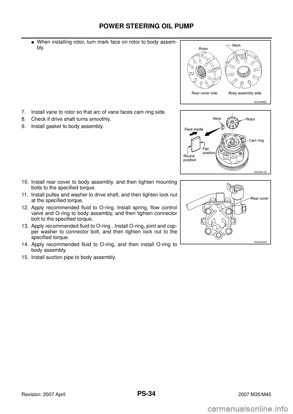
�When installing rotor, turn mark face on rotor to body assem-
bly.
7. Install vane to rotor so that arc of vane faces cam ring side.
8. Check if drive shaft turns smoothly.
9. Install gasket to body assembly.
10. Install rear cover to body assembly, and then tighten mounting
bolts to the specified torque.
11. Install pulley and washer to drive shaft, and then tighten lock nut
at the specified torque.
12. Apply recommended fluid to O-ring. Install spring, flow control
valve and O-ring to body assembly, and then tighten connector
bolt to the specified torque.
13. Apply recommended fluid to O-ring . Install O-ring, joint and cop-
per washer to connector bolt, and then tighten lock nut to the
specified torque.
14. Apply recommended fluid to O-ring, and then install O-ring to
body assembly.
15. Install suction pipe to body assembly.
SGIA0989E
SGIA0613E
SGIA0425E
Page 4021 of 4647
PS-40
HYDRAULIC LINE
Revision: 2007 April2007 M35/M45
10. Eye-bolt 11. Copper washer 12. Eye-joint (assembled to high-pres-
sure side hose)
13. Pressure sensor 14. Oil pump bracket
Refer to GI-11, "
Components" , and the followings for the symbols in the figure.
: Apply power steering fluid.
Page 4022 of 4647
HYDRAULIC LINE
PS-41
C
D
E
F
H
I
J
K
L
MA
B
PS
Revision: 2007 April2007 M35/M45
COMPONENTS (VQ35DE AWD MODELS)
1. Reservoir tank 2. Reservoir tank bracket 3. Suction hose
4. High-pressure hose 5. Oil pump assembly 6. Steering gear assembly
7. Low pressure piping 8. High pressure piping 9. O-ring
10. Eye-bolt 11. Copper washer 12. Eye-joint (assembled to high-pres-
sure side hose)
13. Pressure sensor 14. Oil pump bracket
SGIA1191E
Page 4024 of 4647
HYDRAULIC LINE
PS-43
C
D
E
F
H
I
J
K
L
MA
B
PS
Revision: 2007 April2007 M35/M45
COMPONENTS (VK45DE MODELS)
1. Reservoir tank 2. Reservoir tank bracket 3. Suction hose
4. High-pressure hose 5. Oil pump assembly 6. Steering gear assembly
7. Low pressure piping 8. High pressure piping 9. O-ring
10. Eye-bolt 11. Copper washer 12. Eye-joint (assembled to high-pres-
sure side hose)
13. Pressure sensor 14. Oil pump bracket
SGIA1391E
Page 4070 of 4647

RFD-1
REAR FINAL DRIVE
D DRIVELINE/AXLE
CONTENTS
C
E
F
G
H
I
J
K
L
M
SECTION RFD
A
B
RFD
Revision: 2007 April2007 M35/M45
REAR FINAL DRIVE
PRECAUTIONS .......................................................... 2
Service Notice or Precautions .................................. 2
PREPARATION ........................................................... 3
Special Service Tools ............................................... 3
Commercial Service Tools ........................................ 6
NOISE, VIBRATION AND HARSHNESS (NVH)
TROUBLESHOOTING ................................................ 7
NVH Troubleshooting Chart ..................................... 7
DESCRIPTION ............................................................ 8
Cross-Sectional View ............................................... 8
DIFFERENTIAL GEAR OIL ........................................ 9
Changing Differential Gear Oil ................................. 9
DRAINING ............................................................. 9
FILLING ................................................................. 9
Checking Differential Gear Oil .................................. 9
OIL LEAKAGE AND OIL LEVEL ........................... 9
FRONT OIL SEAL .................................................... 10
Removal and Installation ........................................ 10
IDENTIFICATION STAMP OF REPLACEMENT
FREQUENCY OF FRONT OIL SEAL ................. 10
REMOVAL ........................................................... 10
INSTALLATION ................................................... 12
SIDE OIL SEAL ........................................................ 14
Removal and Installation ........................................ 14
REMOVAL ........................................................... 14
INSTALLATION ................................................... 14REAR FINAL DRIVE ASSEMBLY ............................ 16
Removal and Installation ........................................ 16
COMPONENTS ................................................... 16
REMOVAL ........................................................... 16
INSTALLATION ................................................... 17
Disassembly and Assembly .................................... 18
COMPONENTS ................................................... 18
ASSEMBLY INSPECTION AND ADJUSTMENT ... 19
DISASSEMBLY ................................................... 22
INSPECTION AFTER DISASSEMBLY ................ 26
ADJUSTMENT AND SELECTION OF ADJUST-
ING WASHERS ................................................... 26
ASSEMBLY ......................................................... 31
SERVICE DATA AND SPECIFICATIONS (SDS) ...... 37
General Specifications ............................................ 37
Inspection and Adjustment ..................................... 37
DRIVE GEAR RUNOUT ...................................... 37
DIFFERENTIAL SIDE GEAR CLEARANCE ....... 37
PRELOAD TORQUE ........................................... 37
BACKLASH ......................................................... 37
COMPANION FLANGE RUNOUT ....................... 37
SELECTIVE PARTS ............................................ 38
Page 4074 of 4647
PREPARATION
RFD-5
C
E
F
G
H
I
J
K
L
MA
B
RFD
Revision: 2007 April2007 M35/M45
ST30613000
(J-25742-3)
Drift
a: 72 mm (2.83 in) dia.
b: 48 mm (1.89 in) dia.Installing pinion front bearing outer race
ST30611000
(J-25742-1)
Drift barInstalling pinion front bearing outer race (Use
with ST30613000)
ST30901000
(J-26010-01)
Drift
a: 79 mm (3.11 in) dia.
b: 45 mm (1.77 in) dia.
c: 35.2 mm (1.386 in) dia.Installing pinion rear bearing inner race
KV38100300
(J-25523)
Drift
a: 54 mm (2.13 in) dia.
b: 46 mm (1.81 in) dia.
c: 32 mm (1.26 in) dia.Installing side bearing inner race
(J-8129)
Spring gaugeMeasuring turning torque
(J-34309)
Differential shim selector toolAdjusting bearing preload and pinion gear
height
(J-25269-4)
Side bearing disc (2 Req'd) Selecting pinion height adjusting washer Tool number
(Kent-Moore No.)
Tool nameDescription
ZZA1000D
S-NT090
ZZA0978D
ZZA1046D
NT127
NT134
NT136
Page 4085 of 4647
RFD-16
REAR FINAL DRIVE ASSEMBLY
Revision: 2007 April2007 M35/M45
REAR FINAL DRIVE ASSEMBLYPFP:38300
Removal and InstallationNDS000F7
COMPONENTS
REMOVAL
1. Remove center muffler with a power tool. Refer to EX-3, "EXHAUST SYSTEM" .
2. Remove rear stabilizer bar with a power tool. Refer to RSU-17, "
STABILIZER BAR" .
3. Remove propeller shaft from the final drive. Refer to PR-8, "
Removal and Installation" .
4. Remove drive shaft from final drive with a power tool. Then sus-
pend it by wire etc. Refer to RAX-8, "
REAR DRIVE SHAFT" .
5. Remove breather hose from the final drive.
6. Remove rear wheel sensor. Refer to BRC-54, "
WHEEL SEN-
SOR" .
1. Rear final drive assembly 2. Upper stopper 3. Propeller shaft
4. Washer 5. Lower stopper 6. Drive shaft
A: For VQ35DE models
B: For VK45DE models
Refer to GI-11, "
Components" , for the symbols in the figure.
PDIA0967E
SDIA1094E

13. Pressure sensor 14. Oil pump bracket
Refer to GI-11, \"")

1. Reservoir tank 2. Reservoir tank bracket 3. Suction hose
4. High-pressure hose 5. Oil")

1. Reservoir tank 2. Reservoir tank bracket 3. Suction hose
4. High-pressure hose 5. Oil pump")

Drift
a: 72 mm (2.83 in) dia.
b: 48 mm (1.89 in) dia.Installing pinion front bearing outer race
ST3")
