Page 4523 of 4647

TF-34
TROUBLE DIAGNOSIS FOR SYMPTOMS
Revision: 2007 April2007 M35/M45
2. CHECK AWD CONTROL UNIT POWER SUPPLY CIRCUIT
1. Turn ignition switch “OFF”.
2. Disconnect AWD control unit harness connector.
3. Turn ignition switch “ON”. (Do not start engine.)
4. Check voltage between AWD control unit harness connector ter-
minals and ground.
5. Turn ignition switch “OFF”.
6. Check voltage between AWD control unit harness connector ter-
minals and ground.
OK or NG
OK >> GO TO 3.
NG >> Check the following. If any items are damaged, repair or
replace damaged parts.
�10A fuse [No.33, located in the fuse block (J/B)]
�10A fuse [No.82, located in the IPDM E/R]
�Harness for short or open between battery and AWD control unit harness connector terminal 9
�Harness for short or open between ignition switch and AWD control unit harness connector ter-
minal 7
�Ignition switch. Refer to PG-3, "POWER SUPPLY ROUTING CIRCUIT" .
3. CHECK AWD CONTROL UNIT GROUND CIRCUIT
1. Turn ignition switch “OFF”.
2. Disconnect AWD control unit harness connector.
3. Check continuity between AWD control unit harness connector
F109 terminals 10, 11 and ground.
Also check harness for short to ground and short to power.
OK or NG
OK >> GO TO 4.
NG >> Repair open circuit or short to ground or short to power
in harness or connectors.
Connector Terminal Voltage (Approx.)
F1097 - Ground
Battery voltage
9 - Ground
SDIA2319E
Connector Terminal Voltage (Approx.)
F1097 - Ground 0V
9 - Ground Battery voltage
SDIA2320E
Continuity should exist.
SDIA1883E
Page 4530 of 4647
REAR OIL SEAL
TF-41
C
E
F
G
H
I
J
K
L
MA
B
TF
Revision: 2007 April2007 M35/M45
REAR OIL SEALPFP:33140
Removal and InstallationNDS000E2
REMOVAL
1. Remove the rear propeller shaft. Refer to PR-6, "REAR PROPELLER SHAFT" .
2. Remove self-lock nut of companion flange using a flange
wrench.
3. Put matching mark on the end of the mainshaft. The mark
should be in line with the mark on the companion flange.
CAUTION:
For matching mark, use paint. Do not damage mainshaft.
4. Remove the companion flange using a puller.
CAUTION:
Be careful not to damage the companion flange.
5. Remove the rear oil seal using the puller.
CAUTION:
Be careful not to damage the rear case.
SDIA2454E
SDIA2378E
SDIA1785E
Tool number : KV381054S0 (J-34286)
SDIA1786E
Page 4531 of 4647
TF-42
REAR OIL SEAL
Revision: 2007 April2007 M35/M45
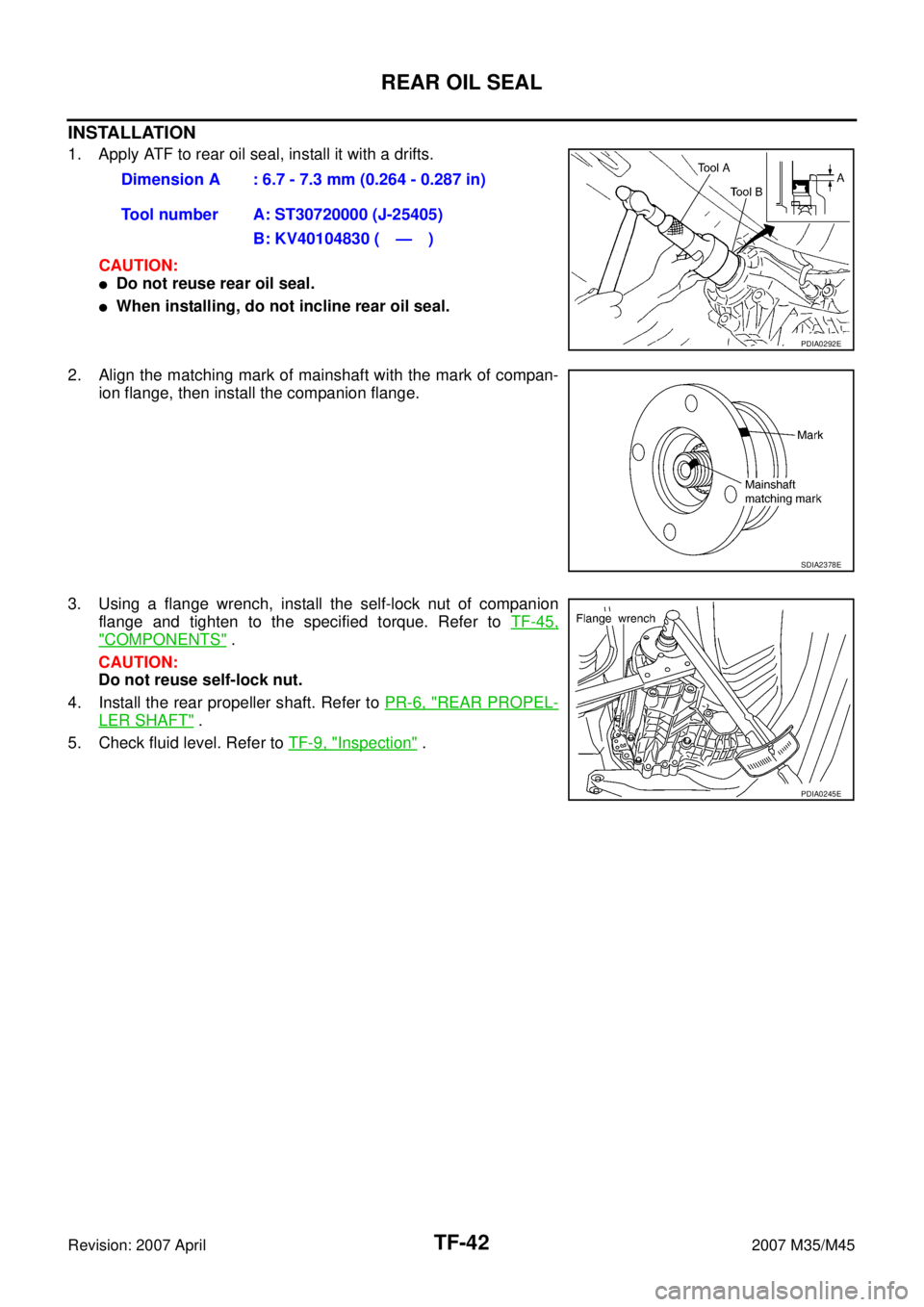
INSTALLATION
1. Apply ATF to rear oil seal, install it with a drifts.
CAUTION:
�Do not reuse rear oil seal.
�When installing, do not incline rear oil seal.
2. Align the matching mark of mainshaft with the mark of compan-
ion flange, then install the companion flange.
3. Using a flange wrench, install the self-lock nut of companion
flange and tighten to the specified torque. Refer to TF-45,
"COMPONENTS" .
CAUTION:
Do not reuse self-lock nut.
4. Install the rear propeller shaft. Refer to PR-6, "
REAR PROPEL-
LER SHAFT" .
5. Check fluid level. Refer to TF-9, "
Inspection" . Dimension A : 6.7 - 7.3 mm (0.264 - 0.287 in)
Tool number A: ST30720000 (J-25405)
B: KV40104830 ( — )
PDIA0292E
SDIA2378E
PDIA0245E
Page 4534 of 4647
TRANSFER ASSEMBLY
TF-45
C
E
F
G
H
I
J
K
L
MA
B
TF
Revision: 2007 April2007 M35/M45
Disassembly and AssemblyNDS000E5
COMPONENTS
*: This may not be used for December ′06 models or later. 1. Drive chain 2. Front drive shaft rear bearing 3. Front drive shaft
4. Front drive shaft front bearing 5. Sprocket 6. Mainshaft
7. Needle bearing 8. Snap ring 9. Mainshaft bearing
10. Front case 11. Front oil seal 12. Mainshaft oil seal
13. Oil cover 14. Temperature sensor* 15. Electric controlled coupling
16. Spacer 17. Snap ring 18. O-ring
19. Oil gutter 20. Drain plug 21. Baffle plate
22. Rear bearing 23. Snap ring 24. Spacer
25. Rear oil seal 26. Companion flange 27. Self-lock nut
28. Breather tube 29. Rear case 30. Harness bracket
31. Retainer 32. Filler plug 33. Gasket
PDIA0244E
Page 4535 of 4647
TF-46
TRANSFER ASSEMBLY
Revision: 2007 April2007 M35/M45
DISASSEMBLY
Front Case and Rear Case
1. Remove drain plug and filler plug.
2. Remove mainshaft oil seal from front case, using a flat-bladed
screwdriver.
CAUTION:
Be careful not to damage the front case and mainshaft.
3. Remove front oil seal from front case, using a flat-bladed screw-
driver.
CAUTION:
Be careful not to damage the front case and front drive
shaft.
4. Remove self-lock nut.
5. Put a matching mark on the end of mainshaft. The mark should
be in line with the mark on the companion flange.
CAUTION:
For matching mark, use paint. Do not damage mainshaft.
6. Remove companion flange, using a puller.
CAUTION:
Be careful not to damage the companion flange.
PDIA0253E
PDIA0255E
SDIA2378E
PDIA0258E
Page 4546 of 4647

TRANSFER ASSEMBLY
TF-57
C
E
F
G
H
I
J
K
L
MA
B
TF
Revision: 2007 April2007 M35/M45
20. Install rear oil seal to rear case, using the drifts.
CAUTION:
�Do not reuse rear oil seal.
�Apply ATF to rear oil seal.
�When installing, do not incline rear oil seal.
21. Install companion flange while align the matching mark of main-
shaft with the mark of companion flange.
22. Tighten self-lock nut to the specified torque, with flange wrench.
Refer to TF-45, "
COMPONENTS" .
CAUTION:
Do not reuse self-lock nut.
23. Install mainshaft oil seal until it is flush with end face of front
case, using the drift.
CAUTION:
�Do not reuse mainshaft oil seal.
�Apply ATF to mainshaft oil seal.
�When installing, do not incline mainshaft oil seal.
24. Install front oil seal until it is flush with end face of front case,
using the drift.
CAUTION:
�Do not reuse front oil seal.
�Apply ATF to front oil seal.
�When installing, do not incline front oil seal.
25. Apply sealant to threads of drain plug. Then install it to rear case
and tighten to the specified torque. Refer to TF-45, "
COMPO-
NENTS" . Dimension A : 6.7 - 7.3 mm (0.264 - 0.287 in)
Tool number A: ST30720000 (J-25405)
B: KV40104830 ( — )
PDIA0281E
SDIA2378E
SDIA2369E
Tool number : ST30720000 (J-25405)
PDIA0282E
Tool number : ST27862000 ( — )
PDIA0287E
Page 4595 of 4647

WW-4
FRONT WIPER AND WASHER SYSTEM
Revision: 2007 April2007 M35/M45
FRONT WIPER AND WASHER SYSTEMPFP:28810
Components Parts and Harness Connector LocationNKS003WB
System DescriptionNKS003WC
�Front wiper relays (HIGH, LOW) are included in IPDM E/R (intelligent power distribution module engine
room).
�Front wiper reverse relay is included in relay box-1. Refer to PG-98, "ELECTRICAL UNITS LOCATION" .
�Wiper switch (combination switch) is composed of a combination of 5 output terminals and 5 input termi-
nals. Terminal combination status is read by BCM (body control module) when switch is turned ON.
�BCM controls front wiper LO, HI, and INT (intermittent) operation.
�IPDM E/R operates wiper motor according to CAN communication signals from BCM.
�Front wiper motor switches LOW speed to/from HIGH speed by BCM function to change polarity.
OUTLINE
Power is supplied at all times
�to ignition relay, located in IPDM E/R, from battery directly,
�through 50 A fusible link (letter F, located in fuse and fusible link block)
�to BCM terminal 55,
�through 10 A fuse [No. 21, located in fuse block (J/B)]
�to BCM terminal 42,
�through 30 A fuse (No. 73, located in IPDM E/R)
�to front wiper low relay, located in IPDM E/R
�to front wiper reverse relay terminal 5,
�through 15 A fuse (No. 78, located in IPDM E/R)
PKID0472E
Page 4596 of 4647
 located in IPDM E/R,
�through 15 A fuse (No. 71, located in IPDM E/R)
�t")
FRONT WIPER AND WASHER SYSTEM
WW-5
C
D
E
F
G
H
I
J
L
MA
B
WW
Revision: 2007 April2007 M35/M45
�to CPU (central processing unit) located in IPDM E/R,
�through 15 A fuse (No. 71, located in IPDM E/R)
�to CPU located in IPDM E/R.
With the ignition switch in the ON or START position, power is supplied
�to ignition relay, located in IPDM E/R,
�through 15 A fuse [No. 1, located in fuse block (J/B)]
�to BCM terminal 38,
�through 10 A fuse [No. 12, located in fuse block (J/B)]
�to front wiper reverse relay terminal 1,
�through 10 A fuse (No. 84, located in IPDM E/R)
�to front washer pump terminal 1
�to front wiper motor terminal 4.
Ground is supplied
�to BCM terminal 52
�through grounds M16 and M70,
�to IPDM E/R terminals 38 and 51
�through grounds E22 and E43,
�to combination switch terminal 12
�through grounds M16 and M70.
LOW SPEED WIPER OPERATION
When wiper switch is in the LO position, BCM detects low speed wiper ON signal by BCM wiper switch read-
ing function.
BCM sends front wiper request signal (LO) with CAN communication line
�from BCM terminals 39 and 40
�to IPDM E/R terminals 49 and 50.
When IPDM E/R receives front wiper request signal (LO), it turns ON front wiper low relay, located in IPDM
E/R, power is supplied
�through IPDM E/R terminal 23 and front wiper high relay and front wiper low relay
�to front wiper motor terminal 3.
Ground is supplied
�to front wiper motor terminal 1
�through front wiper reverse relay terminals 3 and 4
�through grounds E22 and E43.
With power and ground supplied, the front wiper motor operates at low speed.