Page 4593 of 4647

WW-2Revision: 2007 April2007 M35/M45 CHECK VALVE INSPECTION ............................. 47
Inspection of Front Wiper and Washer Switch Circuit ... 47
Removal and Installation of Front Wiper and Washer
Switch ..................................................................... 47
REMOVAL ........................................................... 47
INSTALLATION .................................................... 47
Removal and Installation of Washer Tank .............. 48
REMOVAL ........................................................... 48
INSTALLATION .................................................... 48
Removal and Installation of Washer Pump ............. 49
REMOVAL ........................................................... 49
INSTALLATION .................................................... 49
CIGARETTE LIGHTER ............................................. 50
Wiring Diagram — CIGAR — ................................. 50
Removal and Installation ........................................ 51
REMOVAL ........................................................... 51
INSTALLATION .................................................... 51POWER SOCKET ..................................................... 52
Wiring Diagram — P/SCKT — ................................ 52
Removal and Installation of Center Console Box
Power Socket .......................................................... 53
REMOVAL ............................................................ 53
INSTALLATION .................................................... 53
Removal and Installation of Center Console Box
Rear Side Power Socket ......................................... 53
REMOVAL ............................................................ 53
INSTALLATION .................................................... 53
HORN ........................................................................ 54
Wiring Diagram — HORN — .................................. 54
Removal and Installation ......................................... 55
REMOVAL ............................................................ 55
INSTALLATION .................................................... 55
Page 4594 of 4647

PRECAUTION
WW-3
C
D
E
F
G
H
I
J
L
MA
B
WW
Revision: 2007 April2007 M35/M45
PRECAUTION PFP:00011
Precautions for Supplemental Restraint System (SRS) “AIR BAG” and “SEAT
BELT PRE-TENSIONER”
NKS003WA
The Supplemental Restraint System such as “AIR BAG” and “SEAT BELT PRE-TENSIONER”, used along
with a front seat belt, helps to reduce the risk or severity of injury to the driver and front passenger for certain
types of collision. This system includes seat belt switch inputs and dual stage front air bag modules. The SRS
system uses the seat belt switches to determine the front air bag deployment, and may only deploy one front
air bag, depending on the severity of a collision and whether the front occupants are belted or unbelted.
Information necessary to service the system safely is included in the SRS and SB section of this Service Man-
ual.
WARNING:
�To avoid rendering the SRS inoperative, which could increase the risk of personal injury or death
in the event of a collision which would result in air bag inflation, all maintenance must be per-
formed by an authorized NISSAN/INFINITI dealer.
�Improper maintenance, including incorrect removal and installation of the SRS, can lead to per-
sonal injury caused by unintentional activation of the system. For removal of Spiral Cable and Air
Bag Module, see the SRS section.
�Do not use electrical test equipment on any circuit related to the SRS unless instructed to in this
Service Manual. SRS wiring harnesses can be identified by yellow and/or orange harnesses or
harness connectors.
Page 4602 of 4647

FRONT WIPER AND WASHER SYSTEM
WW-11
C
D
E
F
G
H
I
J
L
MA
B
WW
Revision: 2007 April2007 M35/M45
Wiper Dial Position Setting
Front wiper intermittent operation delay interval is determined from a combination of 3 switches (intermittent
operation dial position 1, 2, and 3) and vehicle speed signal.
After each intermittent operation delay interval, BCM sends front wiper request signal to IPDM E/R.
Example: For wiper dial position 1
Using combination switch reading function, BCM detects ON/OFF status of intermittent operation dial posi-
tions 1, 2, and 3.
When combination switch status is as listed below, BCM determines that it is wiper dial position 1.
�Intermittent operation dial position 1: ON (Continuity exists between combination switch output 3 and input
1.)
�Intermittent operation dial position 2: ON (Continuity exists between combination switch output 5 and input
1.)
�Intermittent operation dial position 3: ON (Continuity exists between combination switch output 4 and input
2.)
BCM determines front wiper intermittent operation delay interval from wiper dial position and vehicle speed,
and sends wiper request signal (INT) to IPDM E/R.
CAN Communication System DescriptionNKS003WD
CAN (Controller Area Network) is a serial communication line for real time application. It is an on-board multi-
plex communication line with high data communication speed and excellent error detection ability. Many elec-
tronic control units are equipped onto a vehicle, and each control unit shares information and links with other
control units during operation (not independent). In CAN communication, control units are connected with 2
communication lines (CAN H line, CAN L line) allowing a high rate of information transmission with less wiring.
Each control unit transmits/receives data but selectively reads required data only.
CAN Communication UnitNKS003WE
Refer to LAN-50, "CAN System Specification Chart" .
Wiper dial positionIntermittent operation
intervalCombination switch
Intermittent operation
dial position 1Intermittent operation
dial position 2Intermittent operation
dial position 3
1
Short
↑
↓
LongON ON ON
2ONONOFF
3ONOFFOFF
4 OFF OFF OFF
5OFFOFFON
6 OFF ON ON
7 OFF ON OFF
Page 4604 of 4647
FRONT WIPER AND WASHER SYSTEM
WW-13
C
D
E
F
G
H
I
J
L
MA
B
WW
Revision: 2007 April2007 M35/M45
Wiring Diagram — WIPER —NKS003WG
TKWT5090E
Page 4615 of 4647

WW-24
FRONT WIPER AND WASHER SYSTEM
Revision: 2007 April2007 M35/M45
Preliminary CheckNKS003WK
CHECK POWER SUPPLY AND GROUND CIRCUIT
1. CHECK FUSES AND FUSIBLE LINK
Check for blown fuses and fusible link.
Refer to WW-13, "
Wiring Diagram — WIPER —" .
OK or NG
OK >> GO TO 2.
NG >> If fuse or fusible link is blown, be sure to eliminate cause of malfunction before installing new fuse
or fusible link. Refer to PG-3, "
POWER SUPPLY ROUTING CIRCUIT" .
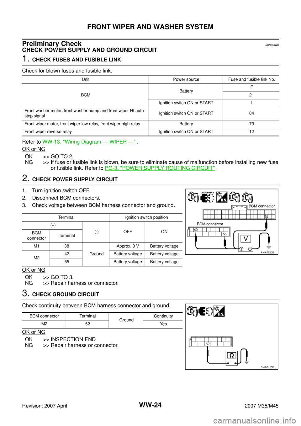
2. CHECK POWER SUPPLY CIRCUIT
1. Turn ignition switch OFF.
2. Disconnect BCM connectors.
3. Check voltage between BCM harness connector and ground.
OK or NG
OK >> GO TO 3.
NG >> Repair harness or connector.
3. CHECK GROUND CIRCUIT
Check continuity between BCM harness connector and ground.
OK or NG
OK >> INSPECTION END
NG >> Repair harness or connector.
Unit Power source Fuse and fusible link No.
BCMBatteryF
21
Ignition switch ON or START 1
Front washer motor, front washer pump and front wiper HI auto
stop signalIgnition switch ON or START 84
Front wiper motor, front wiper low relay, front wiper high relay Battery 73
Front wiper reverse relay Ignition switch ON or START 12
Terminal Ignition switch position
(+)
(-) OFF ON
BCM
connectorTerminal
M1 38
GroundApprox. 0 V Battery voltage
M242 Battery voltage Battery voltage
55 Battery voltage Battery voltage
PKIA7520E
BCM connector Terminal
GroundContinuity
M2 52 Yes
SKIB5125E
Page 4641 of 4647
WW-50
CIGARETTE LIGHTER
Revision: 2007 April2007 M35/M45
CIGARETTE LIGHTERPFP:35330
Wiring Diagram — CIGAR —NKS003X9
TKWT3219E
Page 4643 of 4647
WW-52
POWER SOCKET
Revision: 2007 April2007 M35/M45
POWER SOCKETPFP:253A2
Wiring Diagram — P/SCKT —NKS003XB
TKWT3220E
Page 4645 of 4647
WW-54
HORN
Revision: 2007 April2007 M35/M45
HORNPFP:25610
Wiring Diagram — HORN —NKS003XE
TKWT3221E