Page 3989 of 4647

PS-8
POWER STEERING FLUID
Revision: 2007 April2007 M35/M45
POWER STEERING FLUIDPFP:KLF20
Checking Fluid LevelNGS000D5
�Check fluid level with engine stopped.
�Make sure that fluid level is between MIN and MAX.
�Fluid levels at HOT and COLD are different. Do not confuse
them.
CAUTION:
�The fluid level should not exceed the MAX line. Excessive
fluid will cause fluid leakage from the cap.
�Do not reuse drained power steering fluid.
�Recommended fluid is Genuine Nissan PSF or equiva-
lent.
Checking Fluid LeakageNGS000D6
Check hydraulic connections for fluid leakage, cracks, damage,
looseness, or wear.
1. Run engine until the fluid temperature reaches 50 to 80° C (122
to 176°F) in reservoir tank, and keep engine speed idle.
2. Turn steering wheel several times from full left stop to full right
stop.
3. Hold steering wheel at each lock position for five seconds and
carefully, check for fluid leakage.
CAUTION:
Do not hold the steering wheel in a locked position for more
than 10 seconds. (There is the possibility that oil pump may
be damaged.)
4. If fluid leakage at connections is noticed, then loosen flare nut and then retighten. Do not overtighten con-
nector as this can damage O-ring, washer and connector.
5. If fluid leakage from oil pump is noticed, check oil pump. Refer to PS-30, "
POWER STEERING OIL
PUMP" .
6. Check steering gear boots for accumulation of fluid indicating from steering gear.
Air Bleeding Hydraulic SystemNGS000D7
If air bleeding is not complete, the following symptoms can be observed.
�Bubbles are created in reservoir tank.
�Clicking noise can be heard from oil pump.
�Excessive buzzing in the oil pump.
NOTE:
Fluid noise may occur in the steering gear or oil pump. This does not affect performance or durability of
the system.
1. Turn steering wheel several times from full left stop to full right stop with engine off.
CAUTION:
Filling reservoir tank with fluid so as not to lower fluid level below the MIN line while steering
wheel turning.
2. Start engine and hold steering wheel at each lock position for 3 seconds at idle to check for fluid leakage.
3. Repeat step 2 above several times at approximately 3 second intervals.
CAUTION:
Do not hold the steering wheel in a locked position for more than 10 seconds. (There is the possi-
bility that oil pump may be damaged.)
4. Check fluid for bubbles and while contamination.HOT : Fluid temperature 50 - 80 °C (122 - 176°F)
COLD : Fluid temperature 0 - 30°C (32 - 86°F)
PGIA0007J
SGIA0506E
Page 4006 of 4647

POWER STEERING GEAR AND LINKAGE
PS-25
C
D
E
F
H
I
J
K
L
MA
B
PS
Revision: 2007 April2007 M35/M45
ASSEMBLY
1. Apply recommended fluid to O-ring. Put an O-ring into a rack Teflon ring.
2. Heat rack Teflon ring to approximately 40°C (104°F) with a
dryer. Assemble it to mounting groove of rack assembly.
3. Install the Teflon ring correcting tool [SST] from tooth side of
rack to fit rack Teflon ring on rack. Compress the ring with tool.
4. Apply recommended grease to rack oil seal, and then install
rack oil seal in the following procedure. Then assemble rack
assembly to gear housing assembly.
CAUTION:
�Install rack oil seal in a direction so that the lip of inner oil
seal and the lip of outer oil seal face each other.
�Do not damage retainer sliding surface by rack assembly.
Replace gear housing assembly if damaged.
�Do not damage gear housing assembly inner wall by rack
assembly. Gear housing assembly must be replaced if
damaged because it may cause fluid leakage.
a. Wrap an OHP sheet [approximately 70 mm (2.76 in) × 100 mm
(3.94 in)]. Around rack assembly teeth to avoid damaging rack
oil seal (inner). Install rack oil seal over sheet. Then, pull OHP
sheet along with rack oil seal until they pass rack assembly
teeth, and remove OHP sheet.
SGIA0153E
SGIA0154E
SGIA0205E
SGIA0155E
Page 4007 of 4647
 into rack assembly piston (rack Teflon
ring).
c. Push retainer to adjusting screw side by hand, a")
PS-26
POWER STEERING GEAR AND LINKAGE
Revision: 2007 April2007 M35/M45
b. Insert rack oil seal (inner) into rack assembly piston (rack Teflon
ring).
c. Push retainer to adjusting screw side by hand, and move the
rack assembly inside the gear housing assembly so that the
rack oil seal (inner) can be pressed against the gear housing
assembly.
d. Wrap an OHP sheet [approximately 70 mm (2.76 in) × 100 mm
(3.94 in)]. Around the edge to avoid damaging rack oil seal
(outer). Install rack oil seal over sheet. Then, pull oil seal along
with OHP sheet until they pass rack edge, and remove OHP
sheet.
e. Install end cover assembly to rack edge, and move rack oil seal
(outer) until it contacts with gear housing assembly.
5. Tighten end cover assembly to specified torque using a 36 mm
(1.42 in) open head (suitable tool).
CAUTION:
Do not damage rack assembly. Replace it if damaged
because it may cause fluid leakage.
6. Crimp gear housing assembly at one point using a punch as
shown in the figure so as to prevent end cover assembly from
getting loose after tightening end cover assembly.
7. Apply recommended fluid to O-ring, and then install O-ring to
gear housing assembly.
8. Install gear-sub assembly to gear housing assembly.
9. Install power steering solenoid valve to gear-sub assembly.
10. Decide on the neutral position for the rack.
11. Install rear cover cap to gear sub-assembly.
CAUTION:
Make sure that the projection of rear cover cap is aligned
with the marking position of gear housing assembly.
SGIA0671E
SGIA0157E
SST081B
SGIA0871E
Drive type 2WD AWD
Rack stroke L 68.5 mm (2.697 in) 67.0 mm (2.638 in)
SGIA0877E
Page 4014 of 4647

POWER STEERING OIL PUMP
PS-33
C
D
E
F
H
I
J
K
L
MA
B
PS
Revision: 2007 April2007 M35/M45
ASSEMBLY
NOTE:
Secure oil pump in a vise if necessary.
CAUTION:
Use copper plates when securing in a vise.
1. Apply recommended grease to oil seal lips (1). Apply recom-
mended fluid to around oil seal, and then install oil seal to body
assembly.
2. Apply recommended fluid to drive shaft, and press drive shaft
into body assembly, then install snap ring.
3. Apply recommended fluid to O-ring, and then install O-ring into
body assembly.
4. Install side plate to body assembly.
5. Install dowel pin (3) into dowel pin hole (A), and then install cam
ring (2) pointing it's D
1 side toward the body assembly (1) side
as shown in the figure.
�When installing cam ring, turn carved face with a letter E (B)
of it to rear cover.
CAUTION:
Do not confuse the assembling direction of cam ring. If
cam ring is installed facing the incorrect direction, it may
cause oil pump operation malfunction.
6. Install rotor to body assembly.
SGIA1150E
SGIA0422E
SGIA1166E
Page 4015 of 4647
PS-34
POWER STEERING OIL PUMP
Revision: 2007 April2007 M35/M45
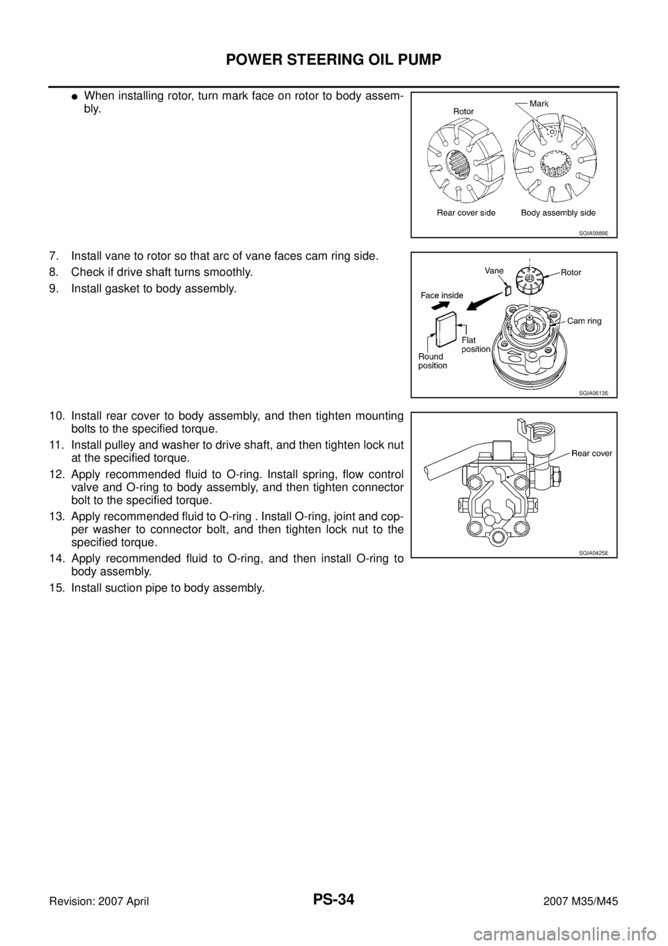
�When installing rotor, turn mark face on rotor to body assem-
bly.
7. Install vane to rotor so that arc of vane faces cam ring side.
8. Check if drive shaft turns smoothly.
9. Install gasket to body assembly.
10. Install rear cover to body assembly, and then tighten mounting
bolts to the specified torque.
11. Install pulley and washer to drive shaft, and then tighten lock nut
at the specified torque.
12. Apply recommended fluid to O-ring. Install spring, flow control
valve and O-ring to body assembly, and then tighten connector
bolt to the specified torque.
13. Apply recommended fluid to O-ring . Install O-ring, joint and cop-
per washer to connector bolt, and then tighten lock nut to the
specified torque.
14. Apply recommended fluid to O-ring, and then install O-ring to
body assembly.
15. Install suction pipe to body assembly.
SGIA0989E
SGIA0613E
SGIA0425E
Page 4018 of 4647

POWER STEERING OIL PUMP
PS-37
C
D
E
F
H
I
J
K
L
MA
B
PS
Revision: 2007 April2007 M35/M45
ASSEMBLY
NOTE:
Secure oil pump in a vise if necessary.
CAUTION:
Use copper plates when securing in a vise.
1. Apply recommended grease to oil seal lips. Apply recommended
fluid to around oil seal, and then install oil seal to body assembly
using the drift [SST].
2. Install bracket to body assembly, and then tighten mounting
bolts to the specified torque.
3. If dowel pin has been removed, insert it into body assembly by
hand. If cannot be inserted by hand, lightly tap with a hammer.
4. Install flow control valve A, flow control valve spring and flow
control valve B assembly as shown in the figure.
5. Install front side plate (3) with dowel pin (2) on flow control valve
A (1) side as shown in the figure aligning with front side plate
cutout (A) to body assembly (4).
6. Install cam ring as shown in the figure.
7. Install pulley to body assembly.
CAUTION:
Do not damage oil seal when installing pulley.
SGIA0527E
SGIA0526E
SGIA1189E
SGIA0612E
Page 4019 of 4647

PS-38
POWER STEERING OIL PUMP
Revision: 2007 April2007 M35/M45
8. Install rotor so that mark faces body assembly, and then install it
to pulley shaft.
9. Install vane to rotor so that arc of vane faces cam ring side.
10. Install rotor snap ring to slit of pulley shaft using a hammer and a
10 mm (0.39 in) socket.
CAUTION:
�Do not damage rotor and pulley shaft.
�Power steering oil pump assembly must be replaced if
rotor is damaged.
11. Install rear side plate with dowel pin A on flow control valve A
side as shown in the figure aligning with rear side plate cutout B
to cartridge.
12. Apply recommended fluid to O-ring, and then install O-ring to
body assembly.
13. Apply recommended fluid to O-ring, and then install O-ring to
rear side plate.
14. Apply recommended fluid to Teflon ring, and then install Teflon
ring to rear side plate.
15. Install rear cover to body assembly, and then tighten mounting
bolts to the specified torque.
16. Apply recommended fluid to O-ring, and then install O-ring to body assembly.
17. Install suction pipe to body assembly.
SGIA0989E
SGIA0613E
SGIA0063E
SGIA0530E
Page 4087 of 4647

RFD-18
REAR FINAL DRIVE ASSEMBLY
Revision: 2007 April2007 M35/M45
Disassembly and AssemblyNDS000F8
COMPONENTS
1. Drive pinion lock nut 2. Companion flange 3. Front oil seal
4. Pinion front bearing 5. Gear carrier 6. Side oil seal
7. Side flange 8. Collapsible spacer 9. Pinion rear bearing
10. Pinion height adjusting washer 11. Drive pinion 12. Side bearing adjusting washer
13. Side bearing 14. Side gear thrust washer 15. Circular clip
16. Side gear 17. Lock pin 18. Pinion mate gear
19. Pinion mate thrust washer 20. Pinion mate shaft 21. Drive gear
22. Differential case 23. Bearing cap 24. Filler plug
25. Gasket 26. Rear cover 27. Drain plug
A: Oil seal lip
B: Screw hole
C: After tightening the bolts to the specified torque, tighten the bolts additionally by turning the bolts 31 to 36 degrees.
Refer to GI-11, "
Components" and the followings for the symbols in the figure.
:Apply gear oil.
:Apply anti-corrosion oil.
:Apply Genuine Silicone RTV or equivalent. Refer to GI-47, "
Recommended Chemical Products and Sealants" .
:Apply Genuine High Strength Thread Locking Sealant or equivalent. Refer to GI-47, "
Recommended Chemical Prod-
ucts and Sealants" .
PDIA0986E