Page 3529 of 4647
LT-78
HEADLAMP (FOR CANADA) - DAYTIME LIGHT SYSTEM -
Revision: 2007 April2007 M35/M45
HEADLAMP (FOR CANADA) - DAYTIME LIGHT SYSTEM -PFP:26010
Component Parts and Harness Connector LocationNKS003P9
System DescriptionNKS003PA
DAYTIME LIGHT SYSTEM turns on daytime light lamps while driving. Daytime light lamps are not turned on if
engine is activated with parking brake on. Take off parking brake to turn on daytime light lamps. The lamps
turn off when lighting switch is in the 2ND position or AUTO position (Head lamp is “ON”) and when lighting
switch is in the PASSING position. (Daytime light lamps are not turned off only by parking brake itself.)
A parking brake signal and engine run or stop signal are sent to BCM (body control module) by CAN commu-
nication line, and control daytime light system.
PKID0500E
Page 3565 of 4647

LT-114
HEADLAMP (FOR CANADA) - DAYTIME LIGHT SYSTEM -
Revision: 2007 April2007 M35/M45
General Information for Xenon Headlamp Trouble DiagnosisNKS003PR
In most cases, malfunction of xenon headlamp - “does not illuminate”, “flickers” or “dark” - is caused by a mal-
functioning xenon bulb. A HID control unit or lamp housing, however, may be a cause of malfunction. Be sure
to perform trouble diagnosis following the steps described below.
CAUTION:NKS003PS
�Installation or removal of connector must be done with lighting switch OFF.
�When lamp is illuminated (when lighting switch is ON), do not touch harness, HID control unit, inside of
lamp, or lamp metal parts.
�To check illumination, temporarily install lamp in the vehicle. Be sure to connect power at the vehicle-side
connector.
�If the error can be traced directly to the electrical system, first check for items such as burned-out fuses
and fusible links, broken wires or loose connectors, pulled-out terminals, and improper connections.
�Do not work with wet hands.
�Using a tester for HID control unit circuit trouble diagnosis is prohibited.
�Disassembling the HID control unit or harnesses (bulb socket harness, ECM harness) is prohibited.
�Immediately after illumination, the light intensity and color will fluctuate, but there is nothing wrong.
�When the bulb has reached the end of its lifetime, the brightness may drop significantly, it may flash
repeatedly, or the light may turn a reddish color.
Xenon Headlamp Trouble DiagnosisNKS003PT
1. CHECK 1: XENON HEADLAMP LIGHTING
Install normal xenon bulb to corresponding xenon bulb headlamp, and check if lamp lights up.
OK or NG
OK >> Replace xenon bulb.
NG >> GO TO 2.
2. CHECK 2: XENON HEADLAMP LIGHTING
Install normal HID control unit to corresponding xenon headlamp, and check if lamp lights up.
OK or NG
OK >> Replace HID control unit.
NG >> GO TO 3.
3. CHECK 3: XENON HEADLAMP LIGHTING
Install normal xenon lamp housing assembly to corresponding xenon headlamp, and check if lamp lights up.
OK or NG
OK >> Replace xenon headlamp housing assembly.
NG >> INSPECTION END
Aiming AdjustmentNKS003PU
Refer to LT- 7 2 , "Aiming Adjustment" .
Bulb ReplacementNKS003PV
Refer to LT- 7 3 , "Bulb Replacement" .
Removal and InstallationNKS003PW
Refer to LT- 7 5 , "Removal and Installation" .
Disassembly and AssemblyNKS003PX
Refer to LT- 7 6 , "Disassembly and Assembly" .
Page 3566 of 4647

AUTO LIGHT SYSTEM
LT-115
C
D
E
F
G
H
I
J
L
MA
B
LT
Revision: 2007 April2007 M35/M45
AUTO LIGHT SYSTEMPFP:28491
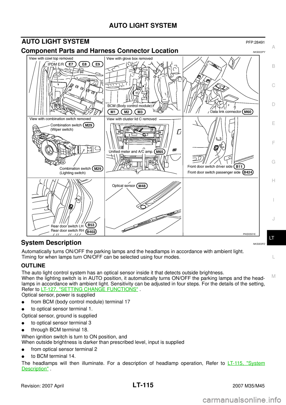
Component Parts and Harness Connector LocationNKS003PY
System DescriptionNKS003PZ
Automatically turns ON/OFF the parking lamps and the headlamps in accordance with ambient light.
Timing for when lamps turn ON/OFF can be selected using four modes.
OUTLINE
The auto light control system has an optical sensor inside it that detects outside brightness.
When the lighting switch is in AUTO position, it automatically turns ON/OFF the parking lamps and the head-
lamps in accordance with ambient light. Sensitivity can be adjusted in four steps. For the details of the setting,
Refer to LT- 1 2 7 , "
SETTING CHANGE FUNCTIONS" .
Optical sensor, power is supplied
�from BCM (body control module) terminal 17
�to optical sensor terminal 1.
Optical sensor, ground is supplied
�to optical sensor terminal 3
�through BCM terminal 18.
When ignition switch is turn to ON position, and
When outside brightness is darker than prescribed level, input is supplied
�from optical sensor terminal 2
�to BCM terminal 14.
The headlamps will then illuminate. For a description of headlamp operation, Refer to LT- 11 5 , "
System
Description" .
PKID0501E
Page 3585 of 4647
LT-134
ACTIVE AFS
Revision: 2007 April2007 M35/M45
ACTIVE AFSPFP:253C0
Component Parts and Harness Connector LocationNKS003QE
System DescriptionNKS003QF
AFS control unit controls AFS and headlamp auto aiming.
The following signals are input to AFS control unit via CAN communication:
�Steering angle sensor signal
�A/T position indicator signal
�Low beam status signal
�Vehicle speed signal
�Engine speed signal
Other signals are input as follows:
�AFS switch signal from AFS switch connected to AFS control unit
PKID0502E
Page 3591 of 4647

LT-140
ACTIVE AFS
Revision: 2007 April2007 M35/M45
Component Parts DescriptionNKS003QG
AFS CONTROL UNIT
AFS control unit determines current vehicle conditions by received signals and controls AFS and headlamp
auto aiming.
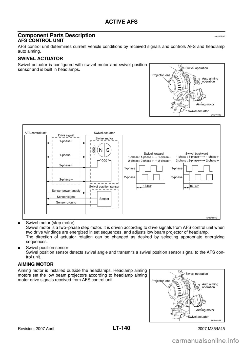
SWIVEL ACTUATOR
Swivel actuator is configured with swivel motor and swivel position
sensor and is built in headlamps.
�Swivel motor (step motor)
Swivel motor is a two−phase step motor. It is driven according to drive signals from AFS control unit when
two drive windings are energized in set sequences, and adjusts low beam projector of headlamp.
The direction of actuator rotation can be changed as desired by selecting appropriate energizing
sequences.
�Swivel position sensor
Swivel position sensor detects swivel angle and transmits a swivel position sensor signal to the AFS con-
trol unit.
AIMING MOTOR
Aiming motor is installed outside the headlamps. Headlamp aiming
motors set the low beam projectors according to headlamp aiming
motor drive signals received from AFS control unit.
SKIB4688E
SKIB4690E
SKIB4688E
Page 3607 of 4647
![INFINITI M35 2007 Factory Service Manual LT-156
ACTIVE AFS
Revision: 2007 April2007 M35/M45
CAUTION:
�If DTC relating to CAN communication [U1000] and other components are displayed at the same
time, diagnose CAN communication first.
�Make s INFINITI M35 2007 Factory Service Manual LT-156
ACTIVE AFS
Revision: 2007 April2007 M35/M45
CAUTION:
�If DTC relating to CAN communication [U1000] and other components are displayed at the same
time, diagnose CAN communication first.
�Make s](/manual-img/42/57024/w960_57024-3606.png)
LT-156
ACTIVE AFS
Revision: 2007 April2007 M35/M45
CAUTION:
�If DTC relating to CAN communication [U1000] and other components are displayed at the same
time, diagnose CAN communication first.
�Make sure of the normal operation after the parts (except AFS control unit) replacement according
to the self-diagnosis results. Delete the malfunction history.
Display Results
�0: There is malfunction now.
�1 – 39: Displays when it is normal at present and finds malfunction in the past. It increases in order
of 0→1→2...38→39 after returning to the normal condition whenever IGN OFF→ON. If it is over 39,
it is fixed to 39 until the self-diagnostic results are erased. It returns to 0 when malfunction is
detected again in the process.
ECU CIRC
[B2521]Any of several statuses below
�Short circuit exists for 2 seconds or longer on power supply
(approx. 12 V) or ground of swivel position sensor (RH) power
supply (AFS control unit terminal 4).
�Short circuit exists for 2 seconds or longer on power supply
(approx. 12 V) of swivel position sensor (RH) signal (AFS con-
trol unit terminal 9).
�Short circuit exists for 2 seconds or longer on power supply
(approx. 12 V) or ground of swivel position sensor (LH) power
supply (AFS control unit terminal 24).
�Short circuit exists for 2 seconds or longer on power supply
(approx. 12 V) of swivel position sensor (LH) signal (AFS con-
trol unit terminal 29).
�Short circuit exists for 2 seconds or longer on power supply
(approx. 12 V) or ground of height sensor power supply (AFS
control unit terminal 6).
�Short circuit exists for 2 seconds or longer on power supply
(approx. 12 V) of height sensor signal (AFS control unit termi-
nal 28).
�AFS control unit (RAM/ROM) malfunctions.1. Stop the swivel motor RH and
LH when the malfunction
occurred.
2. Stop aiming motors when the
malfunction occurred.
3. Flash at intervals of approx. 1
second when keeping error state
for 2 seconds or longer.
4. Turn ignition switch OFF.LT- 1 7 9 , "
DTC
B2521 ECU
CIRC"
ECM SIG
[B2522]Cannot receive engine speed signal.1. Back to the initial position.
2. Stop when the malfunction
occurred.
3. Flash at intervals of approx. 1
second when keeping error state
for 2 seconds or longer.
4. Turn ignition switch OFF.EC-126,
"SELF-DIAG
RESULTS
MODE".
If above sys-
tem is normal,
replace AFS
control unit.
AFS SIG
[B2523]Cannot transmit AFS off indicator signal.1. Back to the initial position.
2. Normal operation
3. Flashes at intervals of approx. 1
second when keeping error state
for 2 seconds or longer.
4. Turn ignition switch OFF.Replace
AFS control
unit LT- 1 9 2
Details of
error
indication
detected by
CONSULT-
IIConditions of error detectionFail-safe
1. Swivel operation
2. Auto aiming operation
3. AFS OFF indicator operation
4. CancellationReference
Page 3645 of 4647
LT-194
FRONT FOG LAMP
Revision: 2007 April2007 M35/M45
FRONT FOG LAMPPFP:26150
Component Parts and Harness Connector LocationNKS003R2
System DescriptionNKS003R3
The control of the fog lamps is dependent upon the position of the combination switch (lighting switch). The
lighting switch must be in the 2ND position or AUTO position (headlamp is ON) for front fog lamp operation.
When the lighting switch is placed in fog lamp position, the BCM (body control module) receives input signal
requesting the fog lamps to illuminate. When the headlamps are illuminated, this input signal is communicated
to the IPDM E/R (intelligent power distribution module engine room) across the CAN communication lines. The
CPU (central processing unit) located in the IPDM E/R controls the front fog lamp relay coil. When activated,
this relay directs power to the front fog lamps.
PKIC1984E
Page 3663 of 4647
LT-212
TURN SIGNAL AND HAZARD WARNING LAMPS
Revision: 2007 April2007 M35/M45
TURN SIGNAL AND HAZARD WARNING LAMPSPFP:26120
Component Parts and Harness Connector LocationNKS003RK
System DescriptionNKS003RL
TURN SIGNAL OPERATION
With the ignition switch is in the ON or START position, power is supplied
�through 15A fuse [No. 1, located in fuse block (J/B)]
�to BCM (body control module) terminal 38,
�through 10A fuse [No. 14, located in fuse block (J/B)]
�to combination meter terminal 12,
�through 10A fuse [No. 12, located in fuse block (J/B)]
�to unified meter and A/C amp. terminal 53.
Ground is supplied
�to BCM terminal 52
�to combination meter terminals 9, 10 and 11
�to unified meter and A/C amp. terminals 55 and 71
�through grounds M16 and M70.
PKIC0620E