Page 4371 of 4647
SE-172
FRONT SEAT
Revision: 2007 April2007 M35/M45
�Remove driver's seat control unit. (Driver's seat only)
�Remove the driver seat control switch.
�Remove seat cushion finisher B and seat cushion finisher C.
�Remove seat harnesses.
Assembly
Assemble in the reverse order of disassembly. Be careful of the following two points.
�Install the hog rings of seat cushion trim in position, and then
securely connect the trim or trim code with the pad side wire.
�Clamp the harness in position.
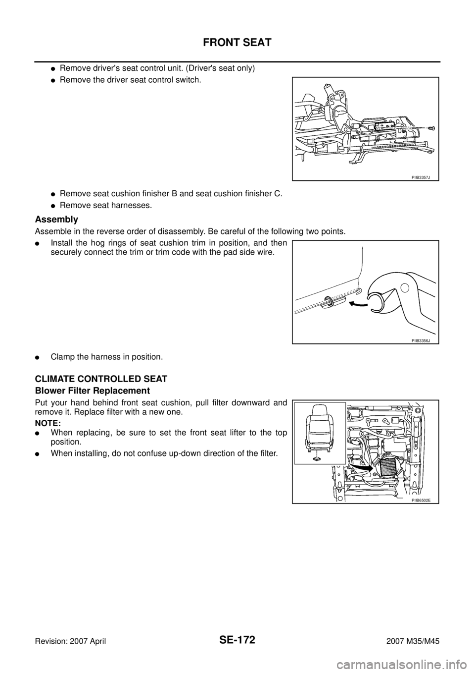
CLIMATE CONTROLLED SEAT
Blower Filter Replacement
Put your hand behind front seat cushion, pull filter downward and
remove it. Replace filter with a new one.
NOTE:
�When replacing, be sure to set the front seat lifter to the top
position.
�When installing, do not confuse up-down direction of the filter.
PIIB3357J
PIIB3356J
PIIB6502E
Page 4376 of 4647

REAR SEAT
SE-177
C
D
E
F
G
H
J
K
L
MA
B
SE
Revision: 2007 April2007 M35/M45
Removal and InstallationNIS0028K
CAUTION:
When removing and installing, use shop cloths to protect parts from damage.
BENCH SEAT
Removal
1. Remove seat cushion.
�Pull the lock lever at the front bottom of the seat cushion for-
ward (1 for each side), and pull the seat cushion upward to
release the wire from the seat cushion hook, then pull the seat
cushion forward to remove.
�Remove the seat cushion from the vehicle.
2. Remove seat back.
�Remove the nuts under seatback.
�Lift up seatback assembly from underneath, and then remove
seatback assembly from seatback hook that is fixed to the
vehicle.
�Remove the headrest.
�Remove the seatback from the vehicle.
Installation
Install in the reverse order of removal. Be careful of the following one point.
Securely engage the upper wire on the back side of seatback with seat hook.
POWER SEAT
Removal
1. Remove seat cushion side.
�Lift seat cushion side up, disengage the seat cushion hook,
and then remove the seat cushion side.
�Remove the seat cushion side from the vehicle.
2. Remove the seat cushion center.
�Disconnect the harness connector.
�Remove the bolts, and then remove the seat cushion center from the vehicle.
3. Remove seatback side.
�Access to the back side of seatback side from the lower, and
then pull the lock lever of seatback hook downward.
�Pull seatback side, and then remove seatback side from the
seatback hook.
: Seatback hook
�Lift up seatback side from underneath, and then remove seatback side from seatback hook.
�Disconnect the harness connector.
PIIB3360J
PIIB4085J
PIIB3359J
Page 4377 of 4647

SE-178
REAR SEAT
Revision: 2007 April2007 M35/M45
�Remove the headrest.
�Remove the seatback side from the vehicle.
4. Remove seatback center.
�Disconnect the harness connector.
�Remove the seatback center mounting bolts and nuts.
�Remove the seatback center from the vehicle.
5. Remove the rear seat frame.
�Disconnect the harness connector.
�Remove the bolts and nuts, and then remove the rear seat frame.
Installation
Install in the reverse order of removal.
Disassembly and AssemblyNIS0028L
BENCH SEAT
Disassembly of Seat Cushion
Remove the hog rings to separate the trim and pad.
Assembly of Seat Cushion
Assemble in the reverse order of disassembly. Be careful of the following one point.
Install hog rings of seat cushion trim in position, and then securely
connect the trim or trim code with the pad side wire.
Disassembly of Seatback
1. Remove the headrest holder.
2. Remove the seat belt guide.
3. Remove the hog rings to separate the trim and pad.
Assembly of Seatback
Assemble in the reverse order of disassembly. Be careful of the following one point.
PIIB3356J
PIIB4084J
Page 4378 of 4647
REAR SEAT
SE-179
C
D
E
F
G
H
J
K
L
MA
B
SE
Revision: 2007 April2007 M35/M45
Install hog rings of seat cushion trim in position, and then securely
connect the trim or trim code with the pad side wire.
Disassembly of Armrest
1. Remove the armrest from seatback.
�Remove the retainer from the side of armrest lid in the back.
�Remove the armrest mounting nuts on the back of seatback.
2. Disassemble the armrest.
�Remove the screws, and then remove armrest lid hinge.
�Remove the armrest lid.
�Remove screws, and then remove the armrest lock assembly from the armrest lid.
PIIB3356J
1. Armrest lid hinge 2. Armrest lid 3. Armrest lock assembly
4. Armrest assembly 5. Rear seat box
PIIB4685J
Page 4379 of 4647

SE-180
REAR SEAT
Revision: 2007 April2007 M35/M45
�Pull the rear seat box rearward and lift up, and then remove
rear seat box from the armrest assembly.
CAUTION:
�When removing, check that front tab is not damaged.
�If the tab is damaged when removing the rear seat box,
replace rear seat box with a new one.
Assembly of Armrest
Assemble in the reverse order of disassembly.
POWER SEAT
Disassembly of Seat Cushion
Remove the hog rings to separate the trim and pad.
Assembly of Seat Cushion
Assemble in the reverse order of disassembly.
Disassembly of Seatback
1. Remove the headrest holder.
2. Remove the seat belt guide.
3. Remove the hog rings to separate the trim and pad.
Assembly of Seatback
Assemble in the reverse order of disassembly. Be careful of the following one point.
Install hog rings of seat cushion trim in position, and then securely
connect the trim or trim code with the pad side wire.
Disassembly of Seat Frame
1. Disconnect the harness connectors, remove the screws,and then remove the rear seat control unit.
2. Remove the seatback hook and seat cushion hook.
Assembly of Seat Frame
Assemble in the reverse order of removal.
Disassembly of Armrest
1. Remove the armrest from seatback center.
�Remove the retainer from the side of armrest lid in the back.
�Remove the armrest mounting nuts on the back of seatback.
PIIB4686J
PIIB4084J
PIIB3356J
Page 4383 of 4647
 SENSOR ................... 50
Removal and Installation ........................................ 50
REMOVAL ............................")
SRS-2Revision: 2007 April2007 M35/M45 SIDE AIR BAG (SATELLITE) SENSOR ................... 50
Removal and Installation ........................................ 50
REMOVAL ........................................................... 50
INSTALLATION .................................................... 50
FRONT SEAT BELT PRE-TENSIONER ................... 51
Removal and Installation ........................................ 51
DIAGNOSIS SENSOR UNIT ..................................... 52
Removal and Installation ........................................ 52
REMOVAL ........................................................... 52
INSTALLATION .................................................... 52
ECU DISCRIMINATED NO. ................................. 52
OCCUPANT CLASSIFICATION SYSTEM CON-TROL UNIT ................................................................ 53
Removal and Installation ......................................... 53
COLLISION DIAGNOSIS .......................................... 54
For Frontal Collision ................................................ 54
SRS INSPECTION (FOR FRONTAL COLLI-
SION) ................................................................... 54
For Side Collision .................................................... 56
WHEN THE SIDE AIR BAG IS ACTIVATED IN
THE SIDE COLLISION: ....................................... 56
WHEN SRS IS NOT ACTIVATED IN THE SIDE
COLLISION: ......................................................... 56
SRS INSPECTION (FOR SIDE COLLISION) ...... 56
Page 4387 of 4647

Revision: 2007 April2007 M35/M45
Front Seat Belt Pre-Tensioner with Load LimiterNHS0008T
The seat belt pre-tensioner system with load limiter is installed for")
SRS-6
SUPPLEMENTAL RESTRAINT SYSTEM (SRS)
Revision: 2007 April2007 M35/M45
Front Seat Belt Pre-Tensioner with Load LimiterNHS0008T
The seat belt pre-tensioner system with load limiter is installed for
both the driver's seat and the front passenger's seat. It operates
simultaneously with the SRS air bag system in the event of a frontal
collision with an impact exceeding a specified level.
When the frontal collision with an impact exceeding a specified level
occurs, seat belt slack resulting from clothing or other factors is
immediately taken up by the pre-tensioner. Vehicle passengers are
securely restrained.
When passengers in a vehicle are thrown forward in a collision and
the restraining force of the seat belt exceeds a specified level, the
load limiter permits the specified extension of the seat belt by the
twisting of the ELR shaft, and a relaxation of the chest-area seat belt
web tension while maintaining force.
Front Side Air BagNHS0008U
Front side air bag is built-in type.
The front seatback with built-in type side air bag have the labels as
shown.
Side Curtain Air BagNHS0008V
The side curtain air bags have the labels as shown.
SRS444
SHIA0170E
BF-2006D
Page 4399 of 4647
![INFINITI M35 2007 Factory Service Manual SRS-18
TROUBLE DIAGNOSIS
Revision: 2007 April2007 M35/M45
CONSULT-II FunctionNHS00094
DIAGNOSIS MODE FOR CONSULT-II
�“SELF-DIAG [CURRENT]”
A current self-diagnosis results (also indicated by the n](/manual-img/42/57024/w960_57024-4398.png "INFINITI M35 2007 Factory Service Manual SRS-18
TROUBLE DIAGNOSIS
Revision: 2007 April2007 M35/M45
CONSULT-II FunctionNHS00094
DIAGNOSIS MODE FOR CONSULT-II
�“SELF-DIAG [CURRENT]”
A current self-diagnosis results (also indicated by the n")
SRS-18
TROUBLE DIAGNOSIS
Revision: 2007 April2007 M35/M45
CONSULT-II FunctionNHS00094
DIAGNOSIS MODE FOR CONSULT-II
�“SELF-DIAG [CURRENT]”
A current self-diagnosis results (also indicated by the number of warning lamp flashes in the Diagnosis
mode) is displayed on the CONSULT-II screen in real time. This refers to a malfunctioning part requiring
repairs.
�“SELF-DIAG [PAST]”
Diagnosis results previously stored in the memory are displayed on the CONSULT-II screen. The stored
results are not erased until memory erasing is executed.
�“TROUBLE DIAG RECORD”
With TROUBLE DIAG RECORD, diagnosis results previously erased by a reset operation can be dis-
played on the CONSULT-II screen.
�“ECU DISCRIMINATED NO.”
The diagnosis sensor unit for each vehicle model is assigned
with its own, individual classification number. This number will
be displayed on the CONSULT-II screen, as shown. When
replacing the diagnosis sensor unit, refer to the part number for
the compatibility. After installation, replacement with a correct
unit can be checked by confirming this classification number on
the CONSULT-II screen.
After repair, make sure the discriminated number of diagnosis
sensor unit installed to vehicle are same. Refer to SRS-52,
"ECU DISCRIMINATED NO." .
�PASSENGER AIR BAG
The STATUS (Readiness) of the front passenger air bag module is displayed.The STATUS displayed
(ON/OFF) depends on the signals supplied to the occupant classification system control module and
air bag diagnosis sensor unit. Refer to SRS-7, "
Occupant Classification System (OCS)" for more infoma-
tion.
HOW TO CHANGE SELF-DIAGNOSIS MODE WITH CONSULT-II
From User Mode to Diagnosis Mode
After selecting “AIR BAG” on the “SELECT SYSTEM” screen, User mode automatically changes to Diagnosis
mode.
From Diagnosis Mode to User Mode
To return to User mode from Diagnosis mode, touch “BACK” key of CONSULT-II until “SELECT SYSTEM”
appears, then diagnosis mode automatically changes to User mode.
PHIA0218E
SRS803
SRS804