Page 4533 of 4647

TF-44
TRANSFER ASSEMBLY
Revision: 2007 April2007 M35/M45
TRANSFER ASSEMBLYPFP:33100
Removal and InstallationNDS000E4
REMOVAL
1. Remove exhaust front tube with power tool. Refer to EX-3, "EXHAUST SYSTEM" .
2. Remove front and rear propeller shaft. Refer to PR-4, "
FRONT PROPELLER SHAFT" and PR-6, "REAR
PROPELLER SHAFT" .
3. Disconnect transfer assembly harness connector and separate harness from transfer assembly.
4. Remove air breather hose. Refer to TF-43, "
AIR BREATHER HOSE" .
5. Remove control rod. Refer to AT- 2 2 6 , "
Control Rod Removal and Installation" .
6. Support transfer assembly and transmission assembly with a jack.
7. Remove rear engine mounting member and engine mounting insulator with power tool. Refer to EM-114,
"ENGINE ASSEMBLY" .
8. Lower jack to the position where the top transfer mounting bolts
can be removed.
9. Remove transfer mounting bolts with power tool and separate
transfer from transmission.
CAUTION:
Secure transfer assembly and transmission assembly to a
jack.
INSTALLATION
Note the following, and install in the reverse order of removal.
�When installing the transfer to the transmission, install the
mounting bolts following the standard below.
�After the installation, check the fluid level, fluid leakage and the
A/T positions. Refer to TF-9, "
Inspection" ,AT- 2 2 7 , "Adjustment
of A/T Position" .
PDIA0560J
Bolt No. 1 2 3 4
Quantity 4 3 2 1
Bolt length “ ” mm (in)75 (2.95) 45 (1.77) 40 (1.57) 30 (1.18)
Tightening torque
N·m (kg-m, ft-lb)37 (3.8, 27)
SDIA2284E
Page 4568 of 4647
 pushed a")
TROUBLE DIAGNOSES
WT-19
C
D
F
G
H
I
J
K
L
MA
B
WT
Revision: 2007 April2007 M35/M45
Transmitter Wake Up OperationNES000JZ
WITH TRANSMITTER ACTIVATION TOOL
1. With the activation tool (J-45295) pushed against the front-left
transmitter, press and hold the button for 5 seconds.
�When ignition switch ON, as the low tire pressure warning
lamp blinks per the follow diagram, the respective transmitter
then must be wake up.
2. Register the ID of wheel that warning lamp flashes. When wake up of registered wheel has been com-
pleted, turn signal lamp flashes two times.
3. After completing wake up all transmitters, make sure low tire pressure warning lamp goes out.
CONSULT-II Function (AIR PRESSURE MONITOR)NES000K0
DESCRIPTION
CONSULT-II can display each diagnostic item using the diagnostic test modes shown following.
CONSULT-II SETTING PROCEDURE
Refer to GI-38, "CONSULT-II Start Procedure" .
SEIA0460E
SEIA0378E
Diagnostic test mode Function Reference
WORK SUPPORTThis mode enables a technician to adjust some devices faster and more
accurately by following the indications on CONSULT-II.WT-20, "
WORK SUP-
PORT MODE"
SELF-DIAG RESULTSReceives self-diagnosis results from low tire pressure warning control
unit and indicates DTCs. WT-20, "SELF-DIAG
RESULT MODE"
DATA MONITORReceives input/output signals from low tire pressure warning control
unit and indicates and stores them to facilitate locating cause of mal-
functions.WT-21, "DATA MONITOR
MODE"
CAN DIAG SUPPORT MNTR Monitors transmitting/receiving status of CAN communication.LAN-44, "CAN Diagnostic
Support Monitor"
ACTIVE TESTDiagnostic Test Mode in with CONSULT-II drives some actuators apart
from the low tire pressure warning control unit and also shifts some
parameters in a specified range.WT-22, "ACTIVE TEST
MODE"
ECU PART NUMBER Displays low tire pressure warning control unit part number. WT-22, "
LOW TIRE PRES-
SURE WARNING CON-
TROL UNIT PART
NUMBER"
Page 4574 of 4647
TROUBLE DIAGNOSES
WT-25
C
D
F
G
H
I
J
K
L
MA
B
WT
Revision: 2007 April2007 M35/M45
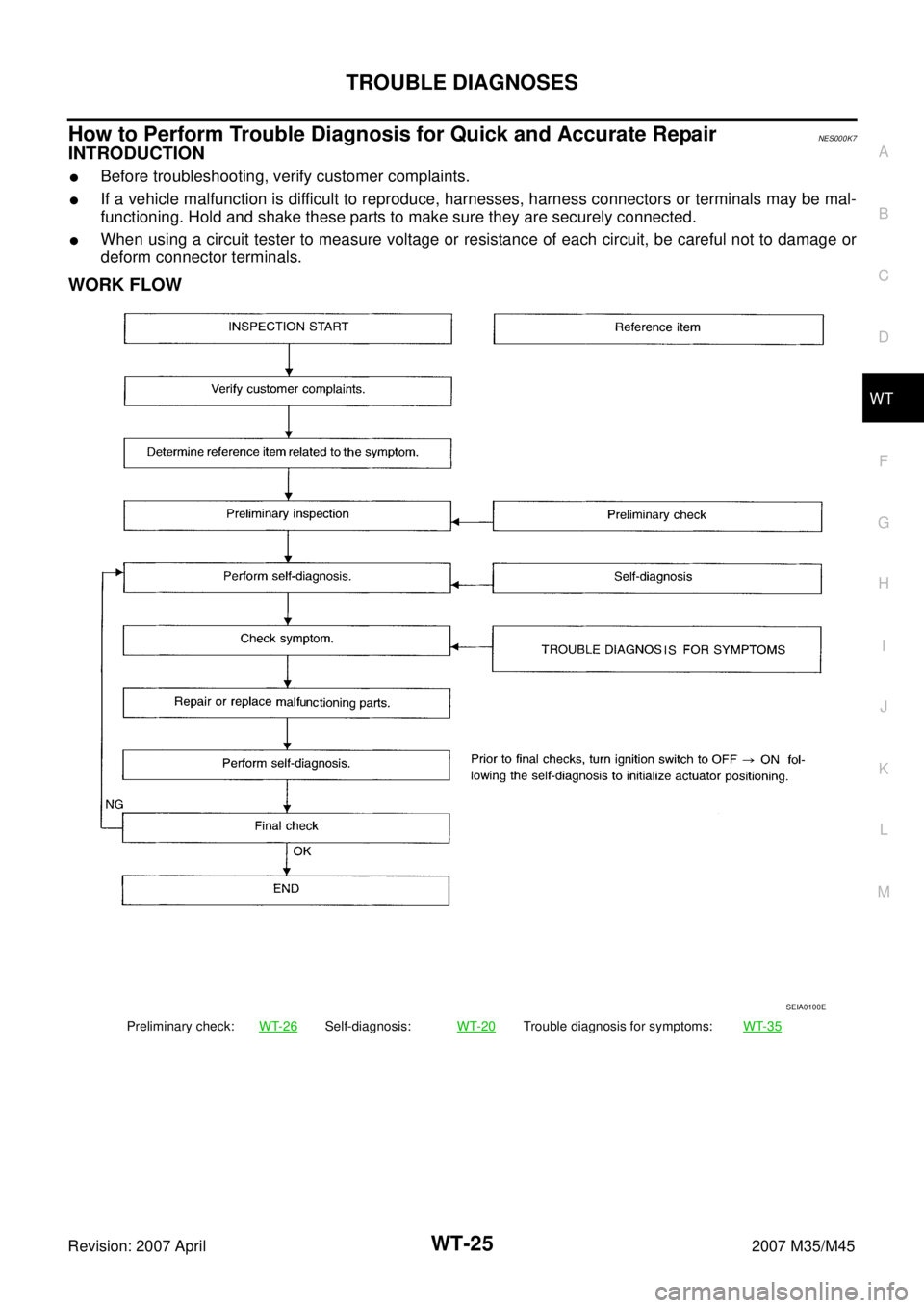
How to Perform Trouble Diagnosis for Quick and Accurate RepairNES000K7
INTRODUCTION
�Before troubleshooting, verify customer complaints.
�If a vehicle malfunction is difficult to reproduce, harnesses, harness connectors or terminals may be mal-
functioning. Hold and shake these parts to make sure they are securely connected.
�When using a circuit tester to measure voltage or resistance of each circuit, be careful not to damage or
deform connector terminals.
WORK FLOW
Preliminary check:WT-26Self-diagnosis:WT-20Trouble diagnosis for symptoms:WT-35
SEIA0100E
Page 4579 of 4647

WT-30
TROUBLE DIAGNOSIS FOR SYSTEM
Revision: 2007 April2007 M35/M45
Receiver Data ErrorNES000KB
MALFUNCTION CODE NO. 25, 26, 27, 28
1. CHECK LOW TIRE PRESSURE WARNING CONTROL UNIT AND RECEIVER CONNECTOR
1. Turn ignition switch OFF, disconnect low tire pressure warning control unit harness connector and receiver
harness connector, and check terminal for deformation, disconnection, looseness, and so on. If there is a
malfunction, repair or replace the terminal.
2. Reconnect harness connector securely, and perform self-diagnosis.
Does
“SELF-DIAG RESULTS” display as normal without any warning lamp?
YES >> Connector terminal connection is loose, damaged, open, or shorted.
NO >> GO TO 2.
2. CHECK TIRE PRESSURE RECEIVER POWER SUPPLY AND GROUND CIRCUIT
1. Turn ignition switch OFF, and disconnect tire pressure receiver harness connector E74, E75, B115, B482.
2. Check continuity between tire pressure receiver harness con-
nector E74, E75, B115, B482 and ground.
3. Turn ignition switch ON, and then check voltage between tire
pressure receiver harness connector E74, E75, B115, B482 and
ground.
OK or NG
OK >> GO TO 3.
NG >> GO TO 4.
3. CHANGE THE TIRE PRESSURE RECEIVER POSITION (EXAMPLE OF FRONT LH SIDE)
1. Replace right from left for front and rear receivers.
2. Perform self-diagnosis.
Is the initial indication of self-diagnosis displayed?
YES >> GO TO 4
NO >> Replace tire pressure receiver front RH when indicating RH tire pressure receiver malfunction.Terminal 4 – Ground : Continuity should exist.
SGIA1249E
1 – Ground : Battery voltage (Approx.12 V)
SGIA1250E
Page 4583 of 4647
 MalfunctionNES000KT
MALFUNCTION CODE NO. 54
1. CHECK SELF-DIAGNOSIS RESULTS
1. Turn ignition switch “ON”.")
WT-34
TROUBLE DIAGNOSIS FOR SYSTEM
Revision: 2007 April2007 M35/M45
Control Unit (EEPROM) MalfunctionNES000KT
MALFUNCTION CODE NO. 54
1. CHECK SELF-DIAGNOSIS RESULTS
1. Turn ignition switch “ON”. (Do not start engine.)
2. Select “SELF-DIAG RESULT” mode for “AIR PRESSURE MONITOR” with CONSULT-II.
3. Touch “ERASE”.
4. Turn ignition switch OFF, and wait at least 10 seconds.
5. Start engine.
6. Perform the self-diagnosis again.
Is the
“CONTROL UNIT (EEPROM) [C1754]” displayed?
YES >> Replace low tire pressure warning control unit. Refer to WT-40, "Low Tire Pressure Warning Con-
trol Unit" .
NO >>INSPECTION END
CAN Communication System MalfunctionNES000KS
1. CHECK LOW TIRE PRESSURE WARNING CONTROL UNIT CONNECTOR
1. Turn ignition switch OFF, disconnect low tire pressure warning control unit harness connector, and check
terminal for deformation, disconnection, looseness, etc.
2. Reconnect harness connector securely, and perform CONSULT-II self-diagnosis.
Is above displayed on self-diagnosis display?
YES >>�If “CAN COMM CIRCUIT [U1000]” is displayed, print out self-diagnosis. And then, go to LAN-
50, "CAN System Specification Chart" .
�Replace low tire pressure warning control unit if “CONTROL UNIT [CAN] [U1010]” is displayed.
NO >> Connector terminal connection is loose, damaged, open, or shorted. Repair or replace the termi-
nal.
Self-diagnostic results
CAN COMM CIRCUIT [U1000]
CONTROL UNIT [CAN] [U1010]