Page 1220 of 4647
BODY REPAIR
BL-287
C
D
E
F
G
H
J
K
L
MA
B
BL
Revision: 2007 April2007 M35/M45
UNDERCOATING
The underside of the floor and wheelhouse are undercoated to prevent rust, vibration, noise and stone chip-
ping. Therefore, when such a panel is replaced or repaired, apply undercoating to that part. Use an undercoat-
ing which is rust preventive, soundproof, vibration-proof, shock-resistant, adhesive, and durable.
Precautions in Undercoating
1. Do not apply undercoating to any place unless specified (such as the areas above the muffler and three
way catalyst which are subjected to heat).
2. Do not undercoat the exhaust pipe or other parts which become hot.
3. Do not undercoat rotating parts.
4. Apply bitumen wax after applying undercoating.
5. After putting seal on the vehicle, put undercoating on it.
SIIA2735E
Page 1242 of 4647

BODY REPAIR
BL-309
C
D
E
F
G
H
J
K
L
MA
B
BL
Revision: 2007 April2007 M35/M45
Rear fender hemming process
1. A wheel arch is to be installed and hemmed over left and right outer wheel house.
2. In order to hem the wheel arch, it is necessary to repair any damaged or defaced parts around outer
wheel house.
CAUTION:
Ensure that the area that is to be glued around outer wheelhouse is undamaged or defaced.
Procedure of the hemming process
�Peel off old bonding material on the surface of outer wheelhouse
and clean thoroughly.
�Peel off a primer coat in the specified area where new adhesive
is to be applied on rear fender (the replacing part).
�Apply new adhesive to both specified areas of outer wheelhouse
and rear fender.
�Attach rear fender to the body of the car, and weld the required
part except the hemming part.
�Bend the welded part starting from the center of the wheel arch
gradually with a hammer and a dolly. (Also hem the end of the
flange.)
�Hemming with a hammer is conducted to an approximate angle
of 80 degrees.
�Starting from the center, hem the wheel arch gradually, using
slight back and forth motion with a hemming tool.
�Seal up the area around the hemmed end of the flange. 3M automix panel bond 8115,
or any equivalents
SIIA2244E
SIIA2245E
SIIA2246E
SIIA2247E
Page 1243 of 4647

BL-310
BODY REPAIR
Revision: 2007 April2007 M35/M45
Foam RepairNIS0028Z
During factory body assembly, foam insulators are installed in certain body panels and locations around the
vehicle. Use the following procedure(s) to replace any factory-installed foam insulators.
URETHANE FOAM APPLICATIONS
Use commercially available spray foam for sealant (foam material) repair of material used on vehicle. Read
instructions on product for fill procedures.
1. Fill procedures after installation of service part.
–Remove foam material remaining on vehicle side.
–Clean area in which foam was removed.
–Install service part.
–Insert nozzle into hole near fill area and fill foam material or fill in enough to close gap with the service
part.
2. Fill procedures before installation of service part.
–Remove foam material remaining on vehicle side.
–Clean area in which foam was removed.
–Fill foam material on wheelhouse outer side.
NOTE:
Fill in enough to close gap with service part while avoiding
flange area.
–Install service part.
NOTE:
Refer to label for information on working times.
LIIA1081E
LIIA1082E
Page 1258 of 4647
BODY REPAIR
BL-325
C
D
E
F
G
H
J
K
L
MA
B
BL
Revision: 2007 April2007 M35/M45
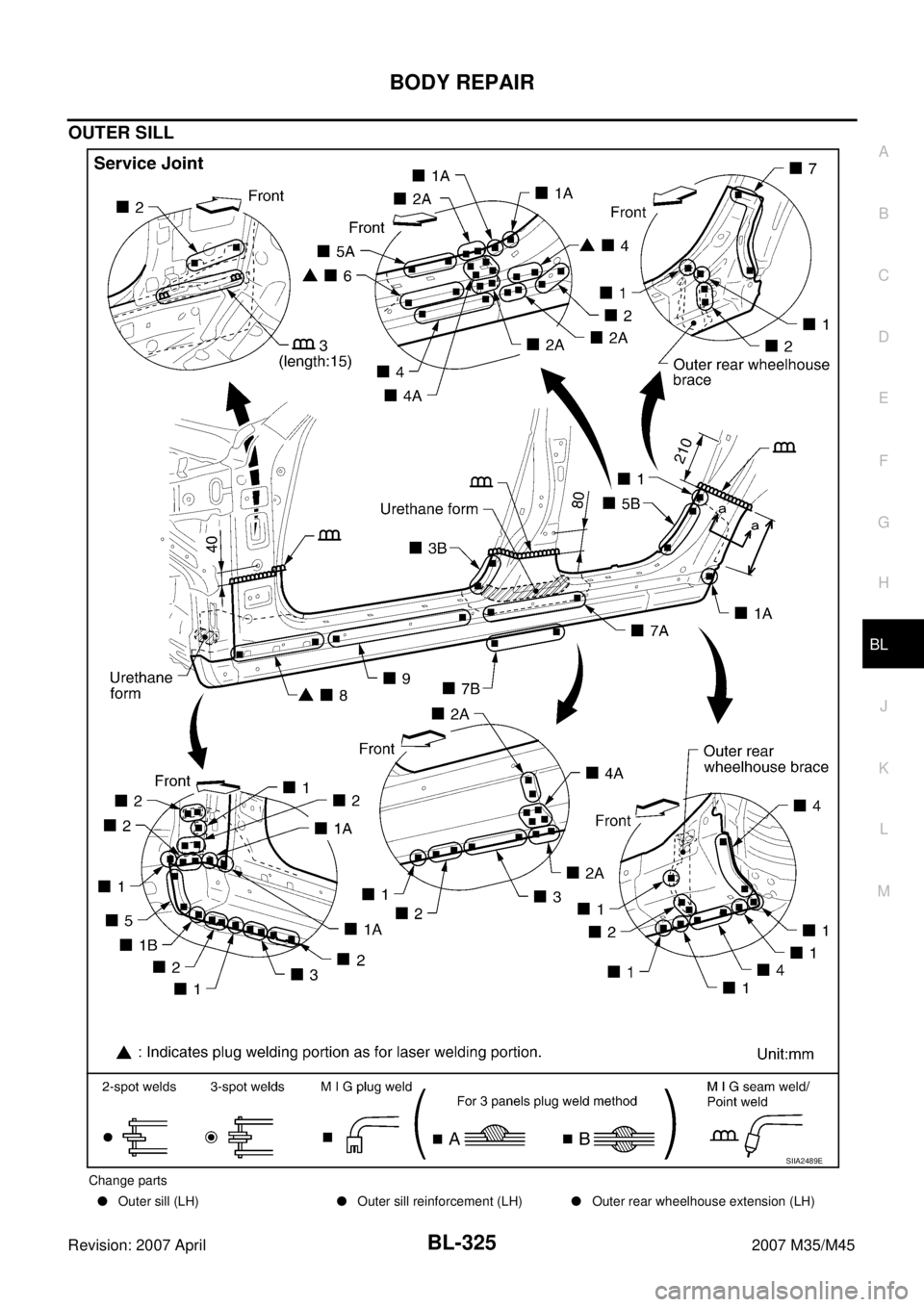
OUTER SILL
Change parts
�Outer sill (LH)�Outer sill reinforcement (LH)�Outer rear wheelhouse extension (LH)
SIIA2489E
Page 1272 of 4647
NOISE, VIBRATION AND HARSHNESS (NVH) TROUBLESHOOTING
BR-5
C
D
E
G
H
I
J
K
L
MA
B
BR
Revision: 2007 April2007 M35/M45
NOISE, VIBRATION AND HARSHNESS (NVH) TROUBLESHOOTINGPFP:00003
NVH Troubleshooting ChartNFS000RS
Use the chart below to help you find the cause of the symptom. If necessary, repair or replace these parts.
×: Applicable Reference page
BR-22
, BR-28
BR-22
, BR-28
BR-22
, BR-28
—
—
BR-27
, BR-33
—
—
—
BR-27
, BR-33
—
NVH in PR section
NHV in FFD and RFD section
NVH in FAX, RAX and FSU, RSU section
NVH in WT section
NVH in WT section
NVH in FAX and RAX section
NVH in PS section
Possible cause and
SUSPECTED PARTS
Pads - damaged
Pads - uneven wear
Shims damaged
Rotor imbalance
Rotor damage
Rotor runout
Rotor deformation
Rotor deflection
Rotor rust
Rotor thickness variation
Drum out of round
PROPELLER SHAFT
DIFFERENTIAL
AXLE AND SUSPENSION
TIRES
ROAD WHEEL
DRIVE SHAFT
STEERING
Symptom BRAKENoise××× ×× ×××
××
Shake×××××
××
Shimmy, Judder××××××× ××× ×
Page 1277 of 4647

BR-10
BRAKE FLUID
Revision: 2007 April2007 M35/M45
3. Make sure there is no foreign material in the reservoir tank, and
refill with new brake fluid.
4. Loosen bleed valve, depress brake pedal slowly to full stroke
and then release it. Repeat the procedure every 2 or 3 seconds
until the new brake fluid comes out, then close the bleed valve
while depressing the pedal. Repeat the same work for each
wheel.
5. Bleed air. Refer to BR-10, "
Bleeding Brake System" .
Bleeding Brake System NFS000RY
CAUTION:
�While bleeding, pay attention to master cylinder fluid level.
�Before working, disconnect connectors of ABS actuator and electric unit (control unit) or battery
cable from the negative terminal.
1. Connect a vinyl tube to rear right brake caliper bleed valve.
2. Fully depress brake pedal 4 or 5 times.
3. With brake pedal depressed, loosen bleed valve to bleed air in brake line, and then tighten it immediately.
4. Repeat steps 2 and 3 until all of the air is out of the brake line.
5. Tighten the bleed valve to the specified torque. Refer to front disc brake: BR-22, "
Components" , rear disc
brake: BR-28, "
Components" .
6. From step 1 to 5, with master cylinder reservoir tank filled at least half way, bleed air from brake hydraulic
line bleed valves in the following order:
Rear right brake→Front left brake→Rear left brake→Front right brake
PFIA0403J
Page 1291 of 4647

BR-24
FRONT DISC BRAKE
Revision: 2007 April2007 M35/M45
Removal and Installation of Brake Caliper AssemblyNFS000SF
REMOVAL
1. Remove tires from vehicle with power tool.
2. Fasten disc rotor using wheel nut.
3. Drain brake fluid. Refer to BR-9, "
Drain and Refill" .
4. Remove union bolt, and then disconnect brake hose from caliper assembly.
5. Remove torque member mounting bolts, and remove brake cali-
per assembly.
CAUTION:
Do not drop brake pad.
6. Remove disc rotor.
CAUTION:
Put matching marks on wheel hub assembly and disc rotor,
if it is necessary to remove disc rotor.
INSTALLATION
CAUTION:
�Refill with new brake fluid “DOT 3”.
�Never reuse drained brake fluid.
1. Install disc rotor.
CAUTION:
Put alignment marks on disc rotor and wheel hub at the time of removal when reusing disc rotor.
2. Install brake caliper assembly to vehicle, and tighten torque member mounting bolts to the specified
torque. Refer to BR-22, "
Components" .
CAUTION:
Do not allow oil or any moisture on all contact surfaces between steering knuckle and caliper
assembly, bolts, and washer.
3. Install brake hose to brake caliper assembly, and tighten union
bolts to the specified torque. Refer to BR-12, "
Removal and
Installation of Front Brake Tube and Brake Hose" .
4. Refill with new brake fluid and bleed air. Refer to BR-10, "
Bleed-
ing Brake System" .
5. Check front disc brake for drag.
6. Install tires to vehicle.
SFIA2437E
SDIA2608E
SFIA2431E
Page 1294 of 4647

FRONT DISC BRAKE
BR-27
C
D
E
G
H
I
J
K
L
MA
B
BR
Revision: 2007 April2007 M35/M45
DISC ROTOR INSPECTION
Visual Inspection
Check surface of disc rotor for uneven wear, cracks, and serious damage. Replace if there are.
Runout Inspection
1. Fix disc rotor to wheel hub using wheel nuts (2 or more posi-
tions).
2. Inspect runout using a dial gauge. [Measured at 10 mm (0.39 in)
inside the disc edge.]
NOTE:
Before measuring, make sure that wheel bearing axial end play
is within the specification. Refer to FAX-5, "
WHEEL BEARING
INSPECTION" .
3. When runout exceeds limit value, displace mounting positions of
disc rotor by one hole. And then find a position of the minimum value for runout.
4. Replace or lathe disc rotor if runout is outside the specified value after performing the above operation.
(“MAD DL-8700”, “AMMCO 700 and 705” or equivalent.)
Thickness Inspection
Check thickness of the disc rotor using a micrometer. Replace disc
rotor if thickness is under the wear limit.
BRAKE BURNISHING PROCEDURE
Burnish contact surfaces between disc rotors and pads according to following procedure after refinishing or
replacing rotors, after replacing pads, or if a soft pedal occurs at very low mileage.
CAUTION:
�Be careful of vehicle speed because the brake does not operate easily until pad and disc rotor are
securely fitted.
�Only perform this procedure under safe road and traffic conditions. Use extreme caution.
1. Drive vehicle on straight, flat road.
2. Depress brake pedal with the power to stop vehicle within 3 to 5 seconds until the vehicle stops.
3. Drive without depressing brake for a few minutes to cool the brake.
4. Repeat steps 1 to 3 until pad and disc rotor are securely fitted.Runout limit : 0.035 mm (0.0014 in)
(with it attached to the vehicle)
BRA0580D
Standard thickness : 28.0 mm (1.102 in)
Wear limit : 26.0 mm (1.024 in)
Thickness variation
(Measured at 8 positions): 0.015 mm (0.0006 in)
SBR020B

 TROUBLESHOOTING
BR-5
C
D
E
G
H
I
J
K
L
MA
B
BR
Revision: 2007 April2007 M35/M45
NOISE, VIBRATION AND HARSHNESS (NVH) TROUBLESHOOTINGPFP:00003
NVH Troubleshooting C")