Page 3794 of 4647
![INFINITI M35 2007 Factory Service Manual ENGINE OIL
LU-29
[VK45DE]
C
D
E
F
G
H
I
J
K
L
MA
LU
Revision: 2007 April2007 M35/M45
6. Install drain plug with new washer. Refer to EM-187, "OIL PAN AND OIL STRAINER" .
CAUTION:
Be sure to clean drai INFINITI M35 2007 Factory Service Manual ENGINE OIL
LU-29
[VK45DE]
C
D
E
F
G
H
I
J
K
L
MA
LU
Revision: 2007 April2007 M35/M45
6. Install drain plug with new washer. Refer to EM-187, "OIL PAN AND OIL STRAINER" .
CAUTION:
Be sure to clean drai](/manual-img/42/57024/w960_57024-3793.png)
ENGINE OIL
LU-29
[VK45DE]
C
D
E
F
G
H
I
J
K
L
MA
LU
Revision: 2007 April2007 M35/M45
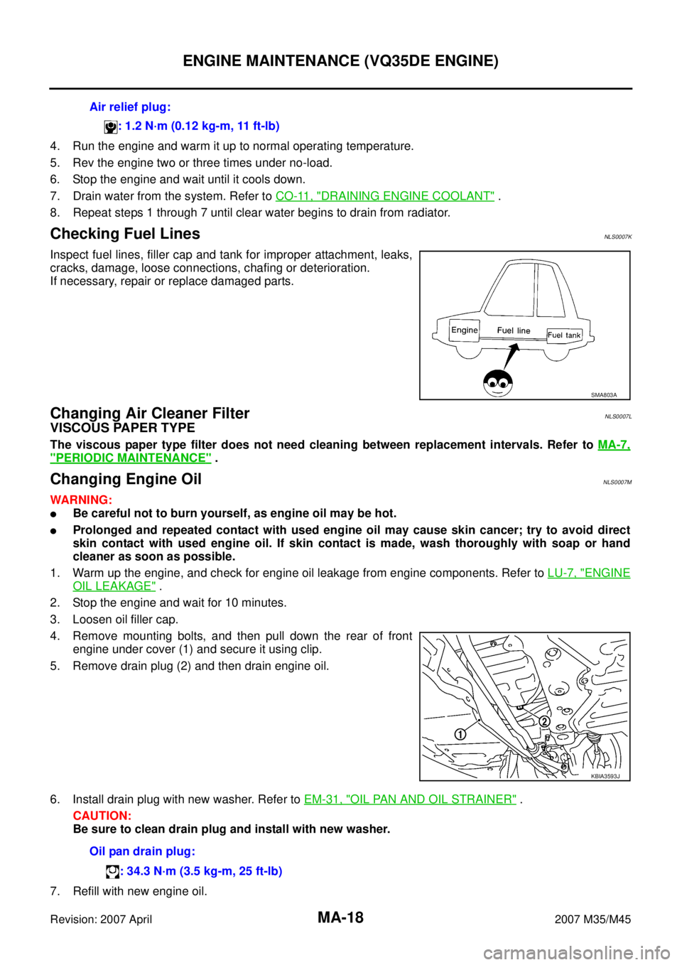
6. Install drain plug with new washer. Refer to EM-187, "OIL PAN AND OIL STRAINER" .
CAUTION:
Be sure to clean drain plug and install with new washer.
7. Refill with new engine oil.
Engine oil specification and viscosity:
Refer to MA-12, "
RECOMMENDED FLUIDS AND LUBRICANTS" .
Engine oil capacity (Approximate):
Unit: (US qt, Imp qt)
CAUTION:
�The refill capacity depends on the engine oil temperature and drain time. Use these specifica-
tions for reference only.
�Always use oil level gauge to determine the proper amount of engine oil in engine.
8. Warm up engine and check area around drain plug and oil filter for oil leakage.
9. Stop engine and wait for 15 minutes.
10. Check the engine oil level. Refer to LU-27, "
ENGINE OIL LEVEL" . Oil pan drain plug:
: 34.3 N·m (3.5 kg-m, 25 ft-lb)
Drain and refillWith oil filter change 5.5 (5-3/4, 4-7/8)
Without oil filter change 4.9 (5-1/8, 4-1/4)
Dry engine (engine overhaul) 6.7 (7-1/8, 5-7/8)
Page 3805 of 4647
MA-6
GENERAL MAINTENANCE
Revision: 2007 April2007 M35/M45
UnderbodyThe underbody is frequently exposed to corrosive substances such as those
used on icy roads or to control dust. It is very important to remove these sub-
stances, otherwise rust will form on the floor pan, frame, fuel lines and around
the exhaust system. At the end of winter, the underbody should be thoroughly
flushed with plain water, being careful to clean those areas where mud and dirt
can easily accumulate.—
Fluid leaksCheck under the vehicle for fuel, oil, water or other fluid leaks after the vehicle
has been parked for a while. Water dripping from the air conditioner after use is
normal. If you should notice any leaks or gasoline fumes are evident, check for
the cause and correct it immediately.— ItemReference page
Page 3817 of 4647

MA-18
ENGINE MAINTENANCE (VQ35DE ENGINE)
Revision: 2007 April2007 M35/M45
4. Run the engine and warm it up to normal operating temperature.
5. Rev the engine two or three times under no-load.
6. Stop the engine and wait until it cools down.
7. Drain water from the system. Refer to CO-11, "
DRAINING ENGINE COOLANT" .
8. Repeat steps 1 through 7 until clear water begins to drain from radiator.
Checking Fuel LinesNLS0007K
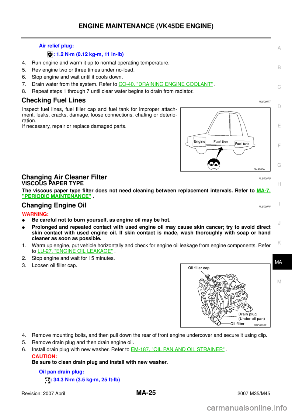
Inspect fuel lines, filler cap and tank for improper attachment, leaks,
cracks, damage, loose connections, chafing or deterioration.
If necessary, repair or replace damaged parts.
Changing Air Cleaner FilterNLS0007L
VISCOUS PAPER TYPE
The viscous paper type filter does not need cleaning between replacement intervals. Refer to MA-7,
"PERIODIC MAINTENANCE" .
Changing Engine OilNLS0007M
WARNING:
�Be careful not to burn yourself, as engine oil may be hot.
�Prolonged and repeated contact with used engine oil may cause skin cancer; try to avoid direct
skin contact with used engine oil. If skin contact is made, wash thoroughly with soap or hand
cleaner as soon as possible.
1. Warm up the engine, and check for engine oil leakage from engine components. Refer to LU-7, "
ENGINE
OIL LEAKAGE" .
2. Stop the engine and wait for 10 minutes.
3. Loosen oil filler cap.
4. Remove mounting bolts, and then pull down the rear of front
engine under cover (1) and secure it using clip.
5. Remove drain plug (2) and then drain engine oil.
6. Install drain plug with new washer. Refer to EM-31, "
OIL PAN AND OIL STRAINER" .
CAUTION:
Be sure to clean drain plug and install with new washer.
7. Refill with new engine oil.Air relief plug:
: 1.2 N·m (0.12 kg-m, 11 ft-lb)
SMA803A
KBIA3593J
Oil pan drain plug:
: 34.3 N·m (3.5 kg-m, 25 ft-lb)
Page 3824 of 4647

ENGINE MAINTENANCE (VK45DE ENGINE)
MA-25
C
D
E
F
G
H
I
J
K
MA
B
MA
Revision: 2007 April2007 M35/M45
4. Run engine and warm it up to normal operating temperature.
5. Rev engine two or three times under no-load.
6. Stop engine and wait until it cools down.
7. Drain water from the system. Refer to CO-40, "
DRAINING ENGINE COOLANT" .
8. Repeat steps 1 through 7 until clear water begins to drain from radiator.
Checking Fuel LinesNLS0007T
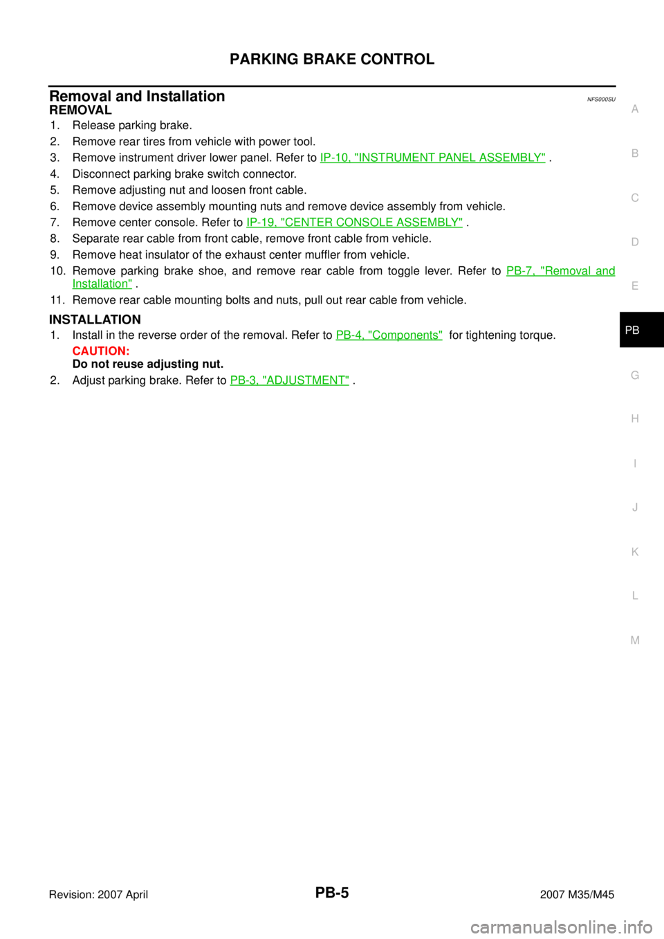
Inspect fuel lines, fuel filler cap and fuel tank for improper attach-
ment, leaks, cracks, damage, loose connections, chafing or deterio-
ration.
If necessary, repair or replace damaged parts.
Changing Air Cleaner FilterNLS0007U
VISCOUS PAPER TYPE
The viscous paper type filter does not need cleaning between replacement intervals. Refer to MA-7,
"PERIODIC MAINTENANCE" .
Changing Engine OilNLS0007V
WARNING:
�Be careful not to burn yourself, as engine oil may be hot.
�Prolonged and repeated contact with used engine oil may cause skin cancer; try to avoid direct
skin contact with used engine oil. If skin contact is made, wash thoroughly with soap or hand
cleaner as soon as possible.
1. Warm up engine, put vehicle horizontally and check for engine oil leakage from engine components. Refer
to LU-27, "
ENGINE OIL LEAKAGE" .
2. Stop engine and wait for 15 minutes.
3. Loosen oil filler cap.
4. Remove mounting bolts, and then pull down the rear of front engine undercover and secure it using clip.
5. Remove drain plug and then drain engine oil.
6. Install drain plug with new washer. Refer to EM-187, "
OIL PAN AND OIL STRAINER" .
CAUTION:
Be sure to clean drain plug and install with new washer.Air relief plug:
: 1.2 N·m (0.12 kg-m, 11 in-lb)
SMA803A
PBIC0993E
Oil pan drain plug:
: 34.3 N·m (3.5 kg-m, 25 ft-lb)
Page 3846 of 4647

PARKING BRAKE CONTROL
PB-5
C
D
E
G
H
I
J
K
L
MA
B
PB
Revision: 2007 April2007 M35/M45
Removal and InstallationNFS000SU
REMOVAL
1. Release parking brake.
2. Remove rear tires from vehicle with power tool.
3. Remove instrument driver lower panel. Refer to IP-10, "
INSTRUMENT PANEL ASSEMBLY" .
4. Disconnect parking brake switch connector.
5. Remove adjusting nut and loosen front cable.
6. Remove device assembly mounting nuts and remove device assembly from vehicle.
7. Remove center console. Refer to IP-19, "
CENTER CONSOLE ASSEMBLY" .
8. Separate rear cable from front cable, remove front cable from vehicle.
9. Remove heat insulator of the exhaust center muffler from vehicle.
10. Remove parking brake shoe, and remove rear cable from toggle lever. Refer to PB-7, "
Removal and
Installation" .
11. Remove rear cable mounting bolts and nuts, pull out rear cable from vehicle.
INSTALLATION
1. Install in the reverse order of the removal. Refer to PB-4, "Components" for tightening torque.
CAUTION:
Do not reuse adjusting nut.
2. Adjust parking brake. Refer to PB-3, "
ADJUSTMENT" .
Page 3849 of 4647

PB-8
PARKING BRAKE SHOE
Revision: 2007 April2007 M35/M45
–Anti-rattle pin for excessive wear and corrosion.
–Return spring for sagging.
�Make sure that adjuster moves smoothly.
�Visually check the inside of drum for excessive wear, cracks, and damage. Check the inside of drum using
a pair of vernier calipers.
�Replace with new part if the above part is malfunction.
INSTALLATION
Note the following, and install in the reverse order of removal.
�Refer to PB-6, "Components" and apply PBC (Poly Butyl Cupry-
sil) grease or silicone-based grease to the specified points dur-
ing assembly.
�Assemble adjusters so that threaded part is expanded when
rotating it in the direction shown by arrow.
�Shorten adjuster by rotating it.
�Check shoe sliding surface and drum inner surface for grease.
Wipe it off if it adhere on the surfaces.
�Perform break-in operation as follows after replacing brake
shoes or disc rotors, or if brakes do not function well.
1. Adjust parking brake pedal stroke to the specified amount. Refer
to PB-3, "
ADJUSTMENT" .
2. Perform parking brake break-in (drag run) operation by driving vehicle under the following conditions:
3. Check parking brake pedal stroke of parking brake. Adjust again if it is outside the standard.Drive forward
�Vehicle speed: Approx. 40 km/h (25 MPH) set (constant and forward)
�Parking brake operating force: Approx. 400 N (40 kg, 89.9 lb) set constant
�Time: Approx. 10 sec.
SFIA2426E
Page 3913 of 4647
PG-62
HARNESS
Revision: 2007 April2007 M35/M45
HARNESS PFP:00011
Harness Layout NKS004ES
HOW TO READ HARNESS LAYOUT
The following Harness Layouts use a map style grid to help locate
connectors on the figures:
�Main Harness (Instrument Panel)
�Engine Room Harness (Engine Compartment)
�Engine Control Harness (Engine Compartment)
�Body Harness
�Body No. 2 Harness
To Use the Grid Reference
1. Find the desired connector number on the connector list.
2. Find the grid reference.
3. On the figure, find the crossing of the grid reference letter column and number row.
4. Find the connector number in the crossing zone.
5. Follow the line (if used) to the connector.
CONNECTOR SYMBOL
Main symbols of connector (in Harness Layout) are indicated in the below.
SEL252V
CKIT0108E
Page 3915 of 4647
PG-64
HARNESS
Revision: 2007 April2007 M35/M45
MAIN HARNESS
Instrument Panel
TKIT0753E