Page 3339 of 4647
IP-12
INSTRUMENT PANEL ASSEMBLY
Revision: 2007 April2007 M35/M45
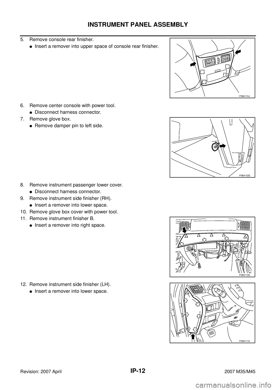
5. Remove console rear finisher.
�Insert a remover into upper space of console rear finisher.
6. Remove center console with power tool.
�Disconnect harness connector.
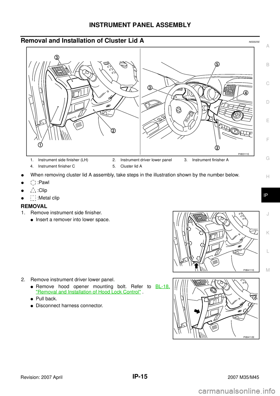
7. Remove glove box.
�Remove damper pin to left side.
8. Remove instrument passenger lower cover.
�Disconnect harness connector.
9. Remove instrument side finisher (RH).
�Insert a remover into lower space.
10. Remove glove box cover with power tool.
11. Remove instrument finisher B.
�Insert a remover into right space.
12. Remove instrument side finisher (LH).
�Insert a remover into lower space.
PIIB4110J
PIIB4152E
PIIB4115E
P I I B 4 111 E
Page 3340 of 4647
INSTRUMENT PANEL ASSEMBLY
IP-13
C
D
E
F
G
H
J
K
L
MA
B
IP
Revision: 2007 April2007 M35/M45
13. Remove instrument driver lower panel.
�Remove hood opener mounting bolt. Refer to BL-18,
"Removal and Installation of Hood Lock Control" .
�Pull back.
�Disconnect harness connector.
14. Remove instrument finisher A.
�Insert a remover into upper space.
15. Remove instrument finisher C.
�Insert a remover into upper space
16. Remove cluster lid A
�Pull back.
17. Remove combination meter. Refer to DI-27, "
Removal and Installation of Combination Meter" .
18. Remove steering column cover with power tool.
19. Remove upper ventilator grille.Refer to ATC-143, "
DUCTS AND GRILLES" .
PIIB4112E
PIIB4113E
PIIB4114E
PIIB6503E
Page 3341 of 4647

IP-14
INSTRUMENT PANEL ASSEMBLY
Revision: 2007 April2007 M35/M45
20. Remove center ventilator grille.
�Insert a remover into rear lower space.
�Pull up.
21. Remove multifunction switch. Refer to AV- 2 8 4 , "
Multifunction Switch" .
22. Remove front display unit. Refer to AV- 2 8 3 , "
Front Display Unit" .
23. Remove audio assembly. Refer to AV- 2 7 7 , "
Audio Unit" .
24. Remove NAVI C/U. Refer to AV- 2 8 2 , "
AV (NAVI) Control Unit" .
25. Remove side ventilator grille (RH/LH).
�Insert a remover into lower space.
�Pull back.
26. Remove front defroster grille.
�Insert a remover into back space.
�Disconnect harness connector.
27. Remove instrument panel & pad.
�Remove front passenger air bag module mounting bolt and disconnect harness connector. Refer to
SRS-46, "
FRONT PASSENGER AIR BAG MODULE" .
�Remove front pillar garnish. Refer to EI-38, "FRONT PILLAR GARNISH" .
INSTALLATION
Install in the reverse order of removal.
CAUTION:
�To install, confirm locating pins on back of instrument panel are completely inserted into holes on
vehicle.
�Do not leave harness stuck when installing.
PIIB4121E
PIIB4123E
PIIB4122E
Page 3342 of 4647
INSTRUMENT PANEL ASSEMBLY
IP-15
C
D
E
F
G
H
J
K
L
MA
B
IP
Revision: 2007 April2007 M35/M45
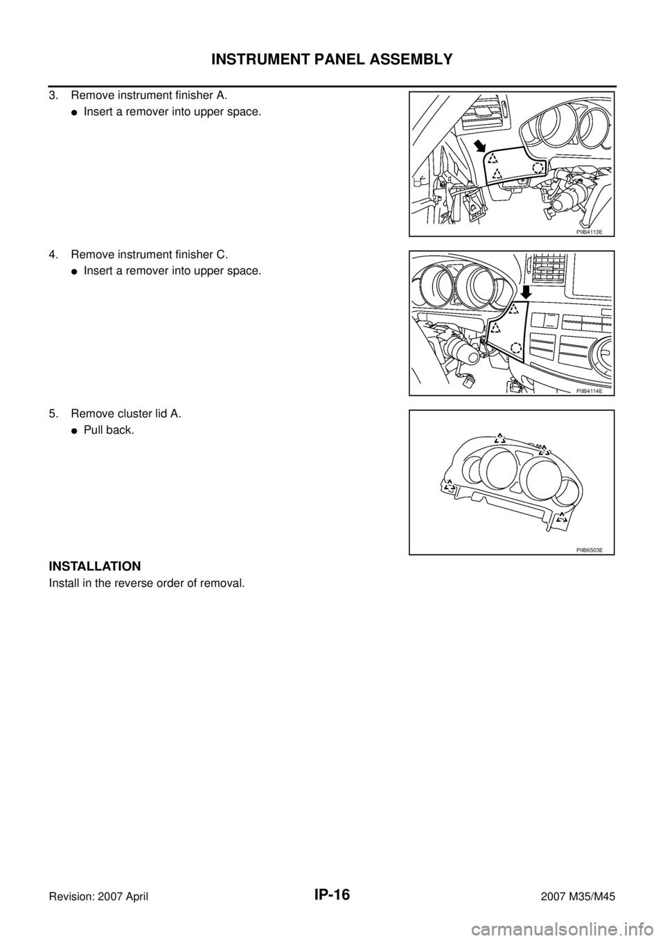
Removal and Installation of Cluster Lid ANIS0025E
�When removing cluster lid A assembly, take steps in the illustration shown by the number below.
� :Pawl
� :Clip
� :Metal clip
REMOVAL
1. Remove instrument side finisher.
�Insert a remover into lower space.
2. Remove instrument driver lower panel.
�Remove hood opener mounting bolt. Refer to BL-18,
"Removal and Installation of Hood Lock Control" .
�Pull back.
�Disconnect harness connector.
1. Instrument side finisher (LH) 2. Instrument driver lower panel 3. Instrument finisher A
4. Instrument finisher C 5. Cluster lid A
P I I B 3 111 E
P I I B 4 111 E
PIIB4112E
Page 3343 of 4647
IP-16
INSTRUMENT PANEL ASSEMBLY
Revision: 2007 April2007 M35/M45
3. Remove instrument finisher A.
�Insert a remover into upper space.
4. Remove instrument finisher C.
�Insert a remover into upper space.
5. Remove cluster lid A.
�Pull back.
INSTALLATION
Install in the reverse order of removal.
PIIB4113E
PIIB4114E
PIIB6503E
Page 3344 of 4647
INSTRUMENT PANEL ASSEMBLY
IP-17
C
D
E
F
G
H
J
K
L
MA
B
IP
Revision: 2007 April2007 M35/M45
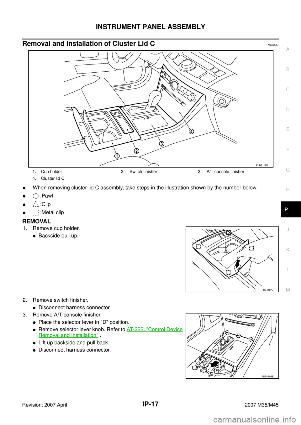
Removal and Installation of Cluster Lid CNIS0025F
�When removing cluster lid C assembly, take steps in the illustration shown by the number below.
� :Pawl
� :Clip
� :Metal clip
REMOVAL
1. Remove cup holder.
�Backside pull up.
2. Remove switch finisher.
�Disconnect harness connector.
3. Remove A/T console finisher.
�Place the selector lever in "D" position.
�Remove selector lever knob. Refer to AT- 2 2 2 , "Control Device
Removal and Installation" .
�Lift up backside and pull back.
�Disconnect harness connector.
1. Cup holder 2. Switch finisher 3. A/T console finisher
4. Cluster lid C
PIIB3112E
PIIB4107J
PIIB4108E
Page 3345 of 4647
IP-18
INSTRUMENT PANEL ASSEMBLY
Revision: 2007 April2007 M35/M45
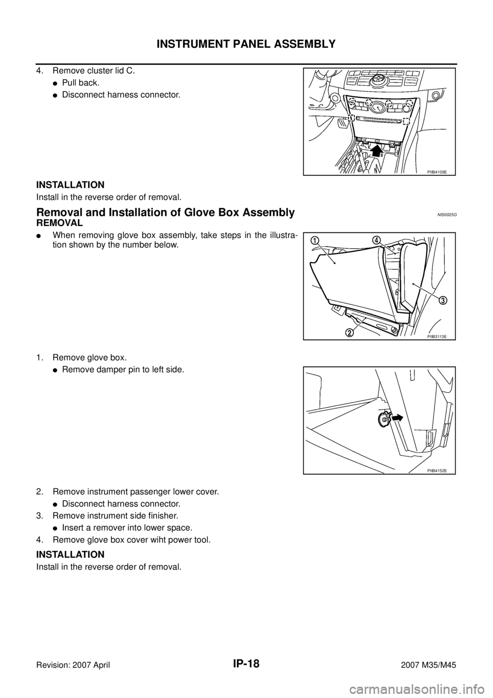
4. Remove cluster lid C.
�Pull back.
�Disconnect harness connector.
INSTALLATION
Install in the reverse order of removal.
Removal and Installation of Glove Box AssemblyNIS0025G
REMOVAL
�When removing glove box assembly, take steps in the illustra-
tion shown by the number below.
1. Remove glove box.
�Remove damper pin to left side.
2. Remove instrument passenger lower cover.
�Disconnect harness connector.
3. Remove instrument side finisher.
�Insert a remover into lower space.
4. Remove glove box cover wiht power tool.
INSTALLATION
Install in the reverse order of removal.
PIIB4109E
PIIB3113E
PIIB4152E
Page 3346 of 4647
INSTRUMENT PANEL ASSEMBLY
IP-19
C
D
E
F
G
H
J
K
L
MA
B
IP
Revision: 2007 April2007 M35/M45
Disassembly and AssemblyNIS0025H
CENTER CONSOLE ASSEMBLY
Disassembly
1. Remove console lid.
2. Remove rear console bracket.
3. Remove console box.
4. Remove DVD pocket cover from console box. (with DVD)
5. Remove DVD player from console box. (with DVD) Refer to AV- 2 8 7 , "
DVD Player" .
6. Remove console lid finisher (RH/LH).
7. Remove console pad (RH/LH) from front console bracket.
8. Remove rear pocket from console rear finisher.
Assembly
Assemble in the reverse order of disassembly.
1. Console lid 2. Rear console bracket 3. Console box
4. DVD pocket cover (with DVD) 5. DVD player (with DVD) 6. Cluster lid finisher (RH)
7. Cluster lid finisher (LH) 8. Front console bracket 9. Console pad (RH)
10. Console pad (LH) 11. Console rear finisher 12. Rear pocket
PIIB3114E