Page 1389 of 4647
![INFINITI M35 2007 Factory Service Manual CO-28
[VQ35DE]
WATER PUMP
Revision: 2007 April2007 M35/M45
b. Apply a continuous bead of liquid gasket with tube presser
(commercial service tool) to mating surface of chain tensioner
cover and water](/manual-img/42/57024/w960_57024-1388.png "INFINITI M35 2007 Factory Service Manual CO-28
[VQ35DE]
WATER PUMP
Revision: 2007 April2007 M35/M45
b. Apply a continuous bead of liquid gasket with tube presser
(commercial service tool) to mating surface of chain tensioner
cover and water")
CO-28
[VQ35DE]
WATER PUMP
Revision: 2007 April2007 M35/M45
b. Apply a continuous bead of liquid gasket with tube presser
(commercial service tool) to mating surface of chain tensioner
cover and water pump cover.
Use Genuine RTV Silicone Sealant or equivalent. Refer to
GI-47, "
RECOMMENDED CHEMICAL PRODUCTS AND
SEALANTS" .
CAUTION:
Attaching should be done within 5 minutes after coating.
c. Tighten mounting bolts.
5. Install water drain plug (front) on water pump side of cylinder block.
�Apply liquid gasket to the thread of water drain plug (front).
Use Genuine RTV Silicone Sealant or equivalent. Refer to GI-47, "
RECOMMENDED CHEMICAL
PRODUCTS AND SEALANTS" .
6. Install in the reverse order of removal for remaining parts.
�After starting engine, let idle for three minutes, then rev engine up to 3,000 rpm under no load to
purge air from the high-pressure chamber of chain tensioner. Engine may produce a rattling
noise. This indicates that air still remains in the chamber and is not a matter of concern.
INSPECTION AFTER INSTALLATION
�Check for leaks of engine coolant using the radiator cap tester adapter (commercial service tool) and the
radiator cap tester (commercial service tool). Refer to CO-11, "
LEAK CHECK" .
�Start and warm up the engine. Visually make sure that there is no leaks of engine coolant.
PBIC2663E
Page 1390 of 4647
![INFINITI M35 2007 Factory Service Manual WATER INLET AND THERMOSTAT ASSEMBLY
CO-29
[VQ35DE]
C
D
E
F
G
H
I
J
K
L
MA
CO
Revision: 2007 April2007 M35/M45
WATER INLET AND THERMOSTAT ASSEMBLYPFP:21200
ComponentsNBS004R3
�Refer to GI-11, "Componen](/manual-img/42/57024/w960_57024-1389.png "INFINITI M35 2007 Factory Service Manual WATER INLET AND THERMOSTAT ASSEMBLY
CO-29
[VQ35DE]
C
D
E
F
G
H
I
J
K
L
MA
CO
Revision: 2007 April2007 M35/M45
WATER INLET AND THERMOSTAT ASSEMBLYPFP:21200
ComponentsNBS004R3
�Refer to GI-11, \"Componen")
WATER INLET AND THERMOSTAT ASSEMBLY
CO-29
[VQ35DE]
C
D
E
F
G
H
I
J
K
L
MA
CO
Revision: 2007 April2007 M35/M45
WATER INLET AND THERMOSTAT ASSEMBLYPFP:21200
ComponentsNBS004R3
�Refer to GI-11, "Components" for symbols in the figure.
Removal and InstallationNBS004R4
REMOVAL
1. Remove engine room cover (RH and LH). Refer to EM-15, "ENGINE ROOM COVER" .
2. Remove air duct (inlet). Refer to EM-19, "
AIR CLEANER AND AIR DUCT" .
3. Remove front engine undercover using power tool.
4. Drain engine coolant from radiator drain plug at the bottom of radiator, and from water drain plug at the
front of cylinder block. Refer to CO-11, "
Changing Engine Coolant" and CO-24, "WATER PUMP" .
CAUTION:
�Perform this step when the engine is cold.
�Do not spill engine coolant on drive belts.
5. Disconnect radiator hose (lower) and oil cooler water hose from water inlet and thermostat assembly.
6. Remove water inlet and thermostat assembly.
CAUTION:
Do not disassemble water inlet and thermostat assembly.
Replace them as a unit, if necessary.
1. Water inlet and thermostat assembly 2. Gasket
A. To oil cooler
PBIC5002E
SLC962AB
Page 1392 of 4647
![INFINITI M35 2007 Factory Service Manual WATER OUTLET AND WATER PIPING
CO-31
[VQ35DE]
C
D
E
F
G
H
I
J
K
L
MA
CO
Revision: 2007 April2007 M35/M45
WATER OUTLET AND WATER PIPINGPFP:11060
ComponentsNBS004R5
Removal and InstallationNBS004R6
REMOV](/manual-img/42/57024/w960_57024-1391.png "INFINITI M35 2007 Factory Service Manual WATER OUTLET AND WATER PIPING
CO-31
[VQ35DE]
C
D
E
F
G
H
I
J
K
L
MA
CO
Revision: 2007 April2007 M35/M45
WATER OUTLET AND WATER PIPINGPFP:11060
ComponentsNBS004R5
Removal and InstallationNBS004R6
REMOV")
WATER OUTLET AND WATER PIPING
CO-31
[VQ35DE]
C
D
E
F
G
H
I
J
K
L
MA
CO
Revision: 2007 April2007 M35/M45
WATER OUTLET AND WATER PIPINGPFP:11060
ComponentsNBS004R5
Removal and InstallationNBS004R6
REMOVAL
1. Remove engine room cover (RH and LH). Refer to EM-15, "ENGINE ROOM COVER" .
2. Remove engine cover with power tool. Refer to EM-21, "
INTAKE MANIFOLD COLLECTOR" .
3. Remove air duct (inlet) and air cleaner case assembly. Refer to EM-19, "
AIR CLEANER AND AIR DUCT"
.
4. Remove front engine undercover with power tool.
5. Drain engine coolant from radiator drain plug at the bottom of radiator, and from water drain plug at the
front of cylinder block. Refer to CO-11, "
Changing Engine Coolant" and CO-24, "WATER PUMP" .
CAUTION:
�Perform this step when the engine is cold.
�Do not spill engine coolant on drive belts.
6. Remove radiator hose (upper) and heater hose.
7. Remove the following parts, when remove water outlet.
�A/T fluid charging pipe: Refer to AT- 2 7 4 , "TRANSMISSION ASSEMBLY" .
�Intake manifold collectors (upper and lower): Refer to EM-21, "INTAKE MANIFOLD COLLECTOR" .
�Rocker cover (right bank): Refer to EM-53, "ROCKER COVER" .
8. Remove engine coolant temperature sensor as necessary.
CAUTION:
Be careful not to damage engine coolant temperature sensor.
1. Harness bracket 2. Water hose 3. Water bypass hose
4. Engine coolant temperature sensor 5. Gasket 6. Water outlet
7. Heater hose 8. Water pipe 9. Radiator hose (upper)
10. Heater pipe 11. Washer 12. O-ring
SBIA0484E
Page 1397 of 4647
![INFINITI M35 2007 Factory Service Manual CO-36
[VK45DE]
OVERHEATING CAUSE ANALYSIS
Revision: 2007 April2007 M35/M45
OVERHEATING CAUSE ANALYSISPFP:00012
Troubleshooting ChartNBS004RB
Symptom Check items
Cooling sys-
tem parts
malfunctionPoor](/manual-img/42/57024/w960_57024-1396.png "INFINITI M35 2007 Factory Service Manual CO-36
[VK45DE]
OVERHEATING CAUSE ANALYSIS
Revision: 2007 April2007 M35/M45
OVERHEATING CAUSE ANALYSISPFP:00012
Troubleshooting ChartNBS004RB
Symptom Check items
Cooling sys-
tem parts
malfunctionPoor")
CO-36
[VK45DE]
OVERHEATING CAUSE ANALYSIS
Revision: 2007 April2007 M35/M45
OVERHEATING CAUSE ANALYSISPFP:00012
Troubleshooting ChartNBS004RB
Symptom Check items
Cooling sys-
tem parts
malfunctionPoor heat transferWater pump malfunction Worn or loose drive belt
— Thermostat and water con-
trol valve stuck closed—
Damaged finsDust contamination or
paper clogging
Physical damage
Clogged radiator cooling
tubeExcess foreign material
(rust, dirt, sand, etc.)
Reduced air flowCooling fan does not oper-
ate
Fan assembly — High resistance to fan rota-
tion
Damaged fan blades
Damaged radiator shroud — — —
Improper engine coolant
mixture ratio—— —
Poor engine coolant quality — Engine coolant density —
Insufficient engine coolantEngine coolant leaksCooling hoseLoose clamp
Cracked hose
Water pump Poor sealing
Radiator capLoose
Poor sealing
RadiatorO-ring for damage, deterio-
ration or improper fitting
Cracked radiator tank
Cracked radiator core
Reservoir tank Cracked reservoir tank
Overflowing reservoir tankExhaust gas leaks into
cooling systemCylinder head deterioration
Cylinder head gasket dete-
rioration
Page 1414 of 4647
![INFINITI M35 2007 Factory Service Manual WATER PUMP
CO-53
[VK45DE]
C
D
E
F
G
H
I
J
K
L
MA
CO
Revision: 2007 April2007 M35/M45
WAT E R P U MPPFP:21020
ComponentsNBS004RP
�Refer to GI-11, "Components" for symbols in the figure.
Removal and I](/manual-img/42/57024/w960_57024-1413.png "INFINITI M35 2007 Factory Service Manual WATER PUMP
CO-53
[VK45DE]
C
D
E
F
G
H
I
J
K
L
MA
CO
Revision: 2007 April2007 M35/M45
WAT E R P U MPPFP:21020
ComponentsNBS004RP
�Refer to GI-11, \"Components\" for symbols in the figure.
Removal and I")
WATER PUMP
CO-53
[VK45DE]
C
D
E
F
G
H
I
J
K
L
MA
CO
Revision: 2007 April2007 M35/M45
WAT E R P U MPPFP:21020
ComponentsNBS004RP
�Refer to GI-11, "Components" for symbols in the figure.
Removal and InstallationNBS004RQ
CAUTION:
�When removing water pump, be careful not to get engine coolant on drive belts.
�Water pump can not be disassembled and should be replaced as a unit.
�After installing water pump, connect hose and clamp securely, then check for leaks using radiator
cap tester (commercial service tool) and radiator cap tester adapter (commercial service tool).
REMOVAL
1. Remove following parts:
�Front engine undercover (power tool)
�Engine cover: Refer to EM-179, "INTAKE MANIFOLD" .
�Engine room cover (RH and LH): Refer to EM-173, "ENGINE ROOM COVER" .
�Air duct (inlet): Refer to EM-177, "AIR CLEANER AND AIR DUCT" .
�Alternator, water pump and A/C compressor belt: Refer to EM-174, "DRIVE BELTS" .
2. Drain engine coolant from drain plugs on radiator and both side of cylinder block. Refer to CO-40, "
Chang-
ing Engine Coolant" and EM-253, "DISASSEMBLY" .
CAUTION:
�Perform this step when engine is cold.
�Do not spill engine coolant on drive belts.
3. Remove water pump pulley.
4. Remove water pump.
�Engine coolant will leak from cylinder block, so have a receptacle ready under vehicle.
CAUTION:
�Handle the water pump vane so that it does not contact any other parts.
�Do not disassemble water pump.
1. Water pump 2. Water pump pulley 3. Gasket
PBIC3396E
Page 1415 of 4647
CO-54
[VK45DE]
WATER PUMP
Revision: 2007 April2007 M35/M45
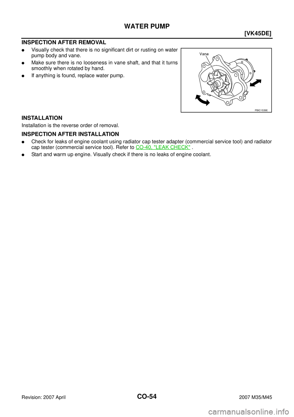
INSPECTION AFTER REMOVAL
�Visually check that there is no significant dirt or rusting on water
pump body and vane.
�Make sure there is no looseness in vane shaft, and that it turns
smoothly when rotated by hand.
�If anything is found, replace water pump.
INSTALLATION
Installation is the reverse order of removal.
INSPECTION AFTER INSTALLATION
�Check for leaks of engine coolant using radiator cap tester adapter (commercial service tool) and radiator
cap tester (commercial service tool). Refer to CO-40, "
LEAK CHECK" .
�Start and warm up engine. Visually check if there is no leaks of engine coolant.
PBIC1539E
Page 1628 of 4647
![INFINITI M35 2007 Factory Service Manual TROUBLE DIAGNOSIS
EC-99
[VQ35DE]
C
D
E
F
G
H
I
J
K
L
MA
EC
Revision: 2007 April2007 M35/M45
Symptom Matrix ChartNBS004T1
SYSTEM — BASIC ENGINE CONTROL SYSTEM
SYMPTOM
Reference
page
HARD/NO START/RE](/manual-img/42/57024/w960_57024-1627.png "INFINITI M35 2007 Factory Service Manual TROUBLE DIAGNOSIS
EC-99
[VQ35DE]
C
D
E
F
G
H
I
J
K
L
MA
EC
Revision: 2007 April2007 M35/M45
Symptom Matrix ChartNBS004T1
SYSTEM — BASIC ENGINE CONTROL SYSTEM
SYMPTOM
Reference
page
HARD/NO START/RE")
TROUBLE DIAGNOSIS
EC-99
[VQ35DE]
C
D
E
F
G
H
I
J
K
L
MA
EC
Revision: 2007 April2007 M35/M45
Symptom Matrix ChartNBS004T1
SYSTEM — BASIC ENGINE CONTROL SYSTEM
SYMPTOM
Reference
page
HARD/NO START/RESTART (EXCP. HA)
ENGINE STALL
HESITATION/SURGING/FLAT SPOT
SPARK KNOCK/DETONATION
LACK OF POWER/POOR ACCELERATION
HIGH IDLE/LOW IDLE
ROUGH IDLE/HUNTING
IDLING VIBRATION
SLOW/NO RETURN TO IDLE
OVERHEATS/WATER TEMPERATURE HIGH
EXCESSIVE FUEL CONSUMPTION
EXCESSIVE OIL CONSUMPTION
BATTERY DEAD (UNDER CHARGE)
Warranty symptom code AA AB AC AD AE AF AG AH AJ AK AL AM HA
Fuel Fuel pump circuit 11232 22 3 2EC-675
Fuel pressure regulator system334444444 4EC-88
Fuel injector circuit 11232 22 2EC-669
Evaporative emission system334444444 4EC-39
Air Positive crankcase ventilation sys-
tem
334444444 41EC-51
Incorrect idle speed adjustment 1 1 1 1 1EC-78
Electric throttle control actuator 112332222 2 2EC-
604,EC-
598 ,EC-
610 ,EC-
615
IgnitionIncorrect ignition timing adjustment33111 11 1EC-78
Ignition circuit 11222 22 2EC-691
Main power supply and ground circuit22333 33 23EC-154
Mass air flow sensor circuit
1
122
222 2EC-193,
EC-202
Engine coolant temperature sensor circuit
333EC-214,
EC-226
Air fuel ratio (A/F) sensor 1 circuitEC-234
,
EC-244
,
EC-253
,
EC-262
,
EC-646
Throttle position sensor circuit
22EC-219
,
EC-342
,
EC-518
,
EC-520
,
EC-631
Accelerator pedal position sensor circuit 3 2 1EC-
617,EC-
624 ,EC-
638 ,EC-
486
Knock sensor circuit 2 3EC-359
Crankshaft position sensor (POS) circuit 2 2EC-364
Page 1631 of 4647
![INFINITI M35 2007 Factory Service Manual EC-102
[VQ35DE]
TROUBLE DIAGNOSIS
Revision: 2007 April2007 M35/M45
1 - 6: The numbers refer to the order of inspection.Exhaust Exhaust manifold/Tube/Muffler/
Gasket
55555 55 5EM-28
, EX-
3Three way ca](/manual-img/42/57024/w960_57024-1630.png "INFINITI M35 2007 Factory Service Manual EC-102
[VQ35DE]
TROUBLE DIAGNOSIS
Revision: 2007 April2007 M35/M45
1 - 6: The numbers refer to the order of inspection.Exhaust Exhaust manifold/Tube/Muffler/
Gasket
55555 55 5EM-28
, EX-
3Three way ca")
EC-102
[VQ35DE]
TROUBLE DIAGNOSIS
Revision: 2007 April2007 M35/M45
1 - 6: The numbers refer to the order of inspection.Exhaust Exhaust manifold/Tube/Muffler/
Gasket
55555 55 5EM-28
, EX-
3Three way catalyst
Lubrica-
tionOil pan/Oil strainer/Oil pump/Oil
filter/Oil gallery/Oil cooler
55555 55 5EM-31
, LU-
19 , LU-11 ,
LU-15
Oil level (Low)/Filthy oilLU-7
Cooling
Radiator/Hose/Radiator filler cap
55555 55 45CO-14,
CO-18
Thermostat 5CO-29
Water pumpCO-24
Water galleryCO-31
Cooling fan
5CO-22
Coolant level (Low)/Contami-
nated coolantCO-11
IVIS (INFINITI Vehicle Immobilizer System —
NATS)11EC-53 or
BL-244
SYMPTOM
Reference
page
HARD/NO START/RESTART (EXCP. HA)
ENGINE STALL
HESITATION/SURGING/FLAT SPOT
SPARK KNOCK/DETONATION
LACK OF POWER/POOR ACCELERATION
HIGH IDLE/LOW IDLE
ROUGH IDLE/HUNTING
IDLING VIBRATION
SLOW/NO RETURN TO IDLE
OVERHEATS/WATER TEMPERATURE HIGH
EXCESSIVE FUEL CONSUMPTION
EXCESSIVE OIL CONSUMPTION
BATTERY DEAD (UNDER CHARGE)
Warranty symptom code AA AB AC AD AE AF AG AH AJ AK AL AM HA