Page 4002 of 4647

POWER STEERING GEAR AND LINKAGE
PS-21
C
D
E
F
H
I
J
K
L
MA
B
PS
Revision: 2007 April2007 M35/M45
Disassembly and AssemblyNGS000DD
COMPONENTS
CAUTION:
�Disassemble and assemble steering gear assembly by securing the mounting area in a vise using
copper plates.
�Clean steering gear assembly with kerosene before disassembling. Be careful to avoid splashing
or applying any kerosene over connector of discharge port or return port.
1. Outer socket 2. Boot clamp 3. Boot
4. Inner socket 5. Boot clamp (stainless wire) 6. End cover assembly
7. Rack oil seal 8. Rack Teflon ring 9. O-ring
10. Rack assembly 11. Gear housing assembly 12. Cylinder tubes
13. O-ring 14. Gear-sub assembly 15. power steering solenoid valve
16. Rear cover cap
Refer to GI-11, "
Components" , and the followings for the symbols in the figure.
: Apply power steering fluid.
: A p p l y G e n u i n e L i q u i d G a s k e t , T h r e e B o n d 1111 B o r e q u i v a l e n t .
: Apply multi-purpose grease.
SGIA1388E
Page 4010 of 4647
POWER STEERING GEAR AND LINKAGE
PS-29
C
D
E
F
H
I
J
K
L
MA
B
PS
Revision: 2007 April2007 M35/M45
�Bent cut end of the wire toward rack axial as shown in the fig-
ure after twisting the wire 4 to 4.5 turns so that cut end does
not contact with boot.
CAUTION:
Keep gap from cylinder tube 5 mm (0.20 in) or more.
23. Install cylinder tubes to gear housing assembly.
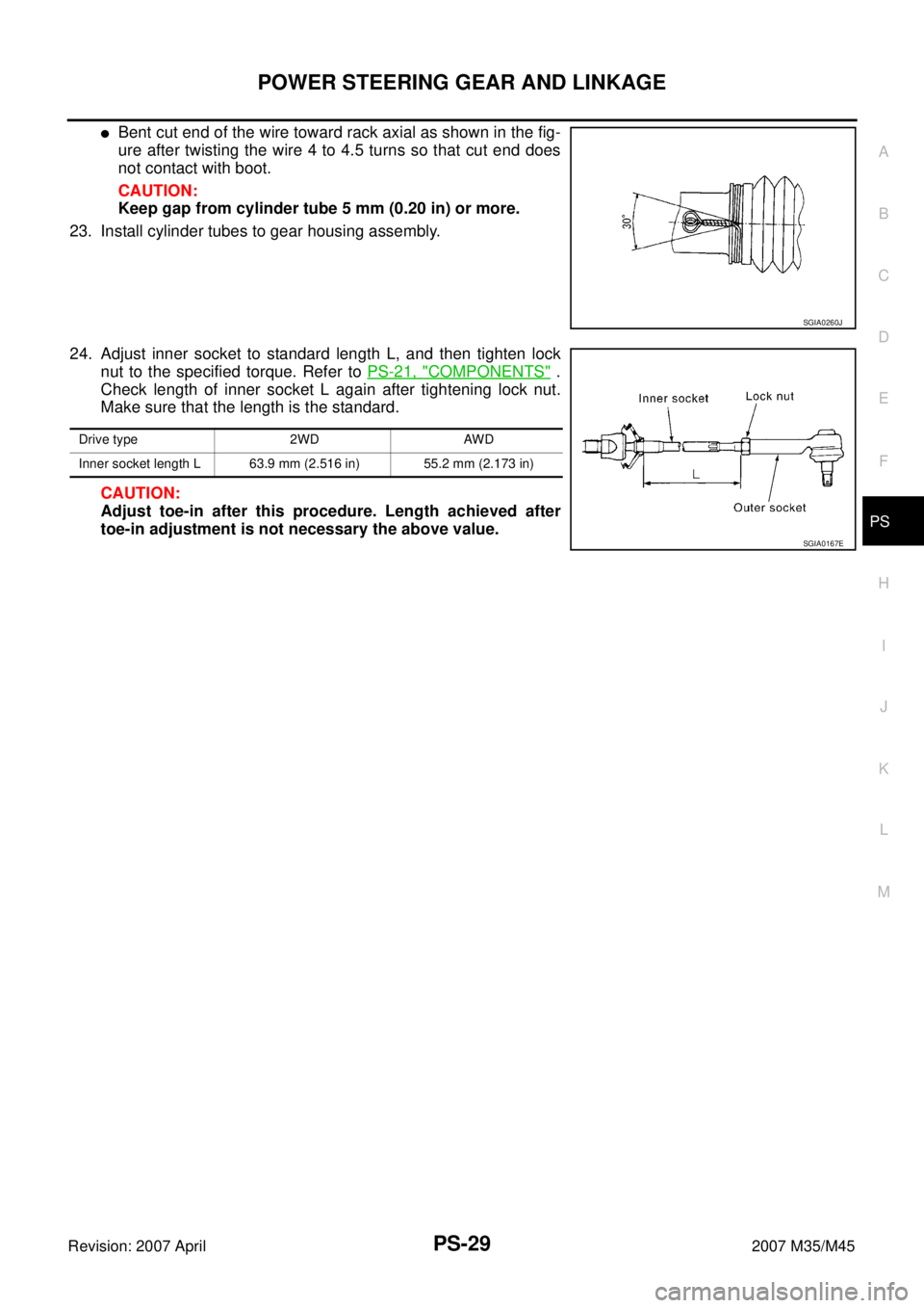
24. Adjust inner socket to standard length L, and then tighten lock
nut to the specified torque. Refer to PS-21, "
COMPONENTS" .
Check length of inner socket L again after tightening lock nut.
Make sure that the length is the standard.
CAUTION:
Adjust toe-in after this procedure. Length achieved after
toe-in adjustment is not necessary the above value.
SGIA0260J
Drive type 2WD AWD
Inner socket length L 63.9 mm (2.516 in) 55.2 mm (2.173 in)
SGIA0167E
Page 4012 of 4647
POWER STEERING OIL PUMP
PS-31
C
D
E
F
H
I
J
K
L
MA
B
PS
Revision: 2007 April2007 M35/M45
Disassembly and Assembly (Models with VK45DE)NGS000DG
COMPONENTS
INSPECTION BEFORE DISASSEMBLY
Disassemble oil pump only when the following malfunctions occur.
�If oil leakage is found on oil pump.
�Oil pump pulley is damaged or deformed.
�Performance of oil pump is low.
1. Pulley 2. Snap ring 3. Drive shaft
4. Joint 5. O-ring 6. Connector bolt
7. Flow control valve 8. Spring 9. Oil seal
10. Suction pipe 11. O-ring 12. Body assembly
13. O-ring 14. Side plate 15. Vane
16. Rotor 17. Cam ring 18. Cartridge
19. Dowel pin 20. Gasket 21. Rear cover
22. Copper washer
Refer to GI-11, "
Components" , and the followings for the symbols in the figure.
: Apply power steering fluid.
: Apply multi-purpose grease.
SGIA1187E
Page 4016 of 4647
POWER STEERING OIL PUMP
PS-35
C
D
E
F
H
I
J
K
L
MA
B
PS
Revision: 2007 April2007 M35/M45
Disassembly and Assembly (Models with VQ35DE)NGS000DH
COMPONENTS
INSPECTION BEFORE DISASSEMBLY
Disassemble oil pump only when the following malfunctions occur.
�If oil leakage is found on oil pump.
�Oil pump pulley is damaged or deformed.
�Performance of oil pump is low.
1. Pulley 2. Oil seal 3. Bracket
4. Body assembly 5. Suction pipe 6. O-ring
7. Flow control valve B assembly 8. Flow control valve spring 9. Flow control valve A
10. Dowel pin 11. Front side plate 12. Vane
13. Rotor 14. Rotor snap ring 15. Cam ring
16. Rear side plate 17. O-ring 18. Teflon ring
19. O-ring 20. Rear cover 21. Cartridge
Refer to GI-11, "
Components" , and the followings for the symbols in the figure.
: Apply power steering fluid.
: Apply multi-purpose grease.
SGIA1188E
Page 4020 of 4647
HYDRAULIC LINE
PS-39
C
D
E
F
H
I
J
K
L
MA
B
PS
Revision: 2007 April2007 M35/M45
HYDRAULIC LINEPFP:49721
Removal and InstallationNGS000DI
COMPONENTS (VQ35DE 2WD MODELS)
1. Reservoir tank 2. Reservoir tank bracket 3. Suction hose
4. High pressure hose 5. Oil pump assembly 6. Steering gear assembly
7. Low pressure piping 8. High pressure piping 9. O-ring
SGIA1390E
Page 4021 of 4647
PS-40
HYDRAULIC LINE
Revision: 2007 April2007 M35/M45
10. Eye-bolt 11. Copper washer 12. Eye-joint (assembled to high-pres-
sure side hose)
13. Pressure sensor 14. Oil pump bracket
Refer to GI-11, "
Components" , and the followings for the symbols in the figure.
: Apply power steering fluid.
Page 4022 of 4647
HYDRAULIC LINE
PS-41
C
D
E
F
H
I
J
K
L
MA
B
PS
Revision: 2007 April2007 M35/M45
COMPONENTS (VQ35DE AWD MODELS)
1. Reservoir tank 2. Reservoir tank bracket 3. Suction hose
4. High-pressure hose 5. Oil pump assembly 6. Steering gear assembly
7. Low pressure piping 8. High pressure piping 9. O-ring
10. Eye-bolt 11. Copper washer 12. Eye-joint (assembled to high-pres-
sure side hose)
13. Pressure sensor 14. Oil pump bracket
SGIA1191E
Page 4023 of 4647
PS-42
HYDRAULIC LINE
Revision: 2007 April2007 M35/M45
Refer to GI-11, "Components" , and the followings for the symbols in the figure.
: Apply power steering fluid.
NGS000DG
COMPONENTS
INSPECTION BEFORE DISASSEMBLY
Disassemble oil")
NGS000DH
COMPONENTS
INSPECTION BEFORE DISASSEMBLY
Disassemble oil")

1. Reservoir tank 2. Reservoir t")

13. Pressure sensor 14. Oil pump bracket
Refer to GI-11, \"")

1. Reservoir tank 2. Reservoir tank bracket 3. Suction hose
4. High-pressure hose 5. Oil")
