Page 3796 of 4647
![INFINITI M35 2007 Factory Service Manual OIL PUMP
LU-31
[VK45DE]
C
D
E
F
G
H
I
J
K
L
MA
LU
Revision: 2007 April2007 M35/M45
OIL PUMPPFP:15010
ComponentsNBS004QF
Removal and InstallationNBS004QG
REMOVAL
1. Remove engine assembly from vehicle.](/manual-img/42/57024/w960_57024-3795.png "INFINITI M35 2007 Factory Service Manual OIL PUMP
LU-31
[VK45DE]
C
D
E
F
G
H
I
J
K
L
MA
LU
Revision: 2007 April2007 M35/M45
OIL PUMPPFP:15010
ComponentsNBS004QF
Removal and InstallationNBS004QG
REMOVAL
1. Remove engine assembly from vehicle.")
OIL PUMP
LU-31
[VK45DE]
C
D
E
F
G
H
I
J
K
L
MA
LU
Revision: 2007 April2007 M35/M45
OIL PUMPPFP:15010
ComponentsNBS004QF
Removal and InstallationNBS004QG
REMOVAL
1. Remove engine assembly from vehicle. Refer to EM-247, "ENGINE ASSEMBLY" .
2. Remove front cover. Refer to EM-203, "
TIMING CHAIN" .
3. Remove oil pump drive spacer.
�Set bolts in the two bolt holes [M6 × pitch 1.0 mm (0.04 in)] on
the front surface. Using suitable puller, pull oil pump drive
spacer off from crankshaft.
NOTE:
The dimension between the centers of the two bolt holes is 33
mm (1.30 in).
In the figure, a commercial steering puller is used.
4. Remove oil pump.
INSTALLATION
1. Install the oil pump.
2. Install oil pump drive spacer as follows:
a. Insert oil pump drive spacer according to the directions of crank-
shaft key and the two flat surfaces of oil pump inner rotor.
�If the positional relationship does not allow the insertion,
rotate oil pump inner rotor with a finger to allow spacer.
b. After confirming that the position of each part is in correct condi-
tion to allow for spacer, force fit spacer by lightly tapping with
plastic hammer until it contacts and does not go further.
1. Oil pump body 2. Oil pump outer rotor 3. Oil pump inner rotor
4. Oil pump cover 5. Oil pump drive spacer 6. Regulator valve
7. Regulator valve spring 8. Regulator valve plug
PBIC1592E
PBIC0054E
PBIC0058E
Page 3817 of 4647

Revision: 2007 April2007 M35/M45
4. Run the engine and warm it up to normal operating temperature.
5. Rev the engine two or three times under no-load.
6. Stop")
MA-18
ENGINE MAINTENANCE (VQ35DE ENGINE)
Revision: 2007 April2007 M35/M45
4. Run the engine and warm it up to normal operating temperature.
5. Rev the engine two or three times under no-load.
6. Stop the engine and wait until it cools down.
7. Drain water from the system. Refer to CO-11, "
DRAINING ENGINE COOLANT" .
8. Repeat steps 1 through 7 until clear water begins to drain from radiator.
Checking Fuel LinesNLS0007K
Inspect fuel lines, filler cap and tank for improper attachment, leaks,
cracks, damage, loose connections, chafing or deterioration.
If necessary, repair or replace damaged parts.
Changing Air Cleaner FilterNLS0007L
VISCOUS PAPER TYPE
The viscous paper type filter does not need cleaning between replacement intervals. Refer to MA-7,
"PERIODIC MAINTENANCE" .
Changing Engine OilNLS0007M
WARNING:
�Be careful not to burn yourself, as engine oil may be hot.
�Prolonged and repeated contact with used engine oil may cause skin cancer; try to avoid direct
skin contact with used engine oil. If skin contact is made, wash thoroughly with soap or hand
cleaner as soon as possible.
1. Warm up the engine, and check for engine oil leakage from engine components. Refer to LU-7, "
ENGINE
OIL LEAKAGE" .
2. Stop the engine and wait for 10 minutes.
3. Loosen oil filler cap.
4. Remove mounting bolts, and then pull down the rear of front
engine under cover (1) and secure it using clip.
5. Remove drain plug (2) and then drain engine oil.
6. Install drain plug with new washer. Refer to EM-31, "
OIL PAN AND OIL STRAINER" .
CAUTION:
Be sure to clean drain plug and install with new washer.
7. Refill with new engine oil.Air relief plug:
: 1.2 N·m (0.12 kg-m, 11 ft-lb)
SMA803A
KBIA3593J
Oil pan drain plug:
: 34.3 N·m (3.5 kg-m, 25 ft-lb)
Page 3824 of 4647

MA-25
C
D
E
F
G
H
I
J
K
MA
B
MA
Revision: 2007 April2007 M35/M45
4. Run engine and warm it up to normal operating temperature.
5. Rev engine two or three times under")
ENGINE MAINTENANCE (VK45DE ENGINE)
MA-25
C
D
E
F
G
H
I
J
K
MA
B
MA
Revision: 2007 April2007 M35/M45
4. Run engine and warm it up to normal operating temperature.
5. Rev engine two or three times under no-load.
6. Stop engine and wait until it cools down.
7. Drain water from the system. Refer to CO-40, "
DRAINING ENGINE COOLANT" .
8. Repeat steps 1 through 7 until clear water begins to drain from radiator.
Checking Fuel LinesNLS0007T
Inspect fuel lines, fuel filler cap and fuel tank for improper attach-
ment, leaks, cracks, damage, loose connections, chafing or deterio-
ration.
If necessary, repair or replace damaged parts.
Changing Air Cleaner FilterNLS0007U
VISCOUS PAPER TYPE
The viscous paper type filter does not need cleaning between replacement intervals. Refer to MA-7,
"PERIODIC MAINTENANCE" .
Changing Engine OilNLS0007V
WARNING:
�Be careful not to burn yourself, as engine oil may be hot.
�Prolonged and repeated contact with used engine oil may cause skin cancer; try to avoid direct
skin contact with used engine oil. If skin contact is made, wash thoroughly with soap or hand
cleaner as soon as possible.
1. Warm up engine, put vehicle horizontally and check for engine oil leakage from engine components. Refer
to LU-27, "
ENGINE OIL LEAKAGE" .
2. Stop engine and wait for 15 minutes.
3. Loosen oil filler cap.
4. Remove mounting bolts, and then pull down the rear of front engine undercover and secure it using clip.
5. Remove drain plug and then drain engine oil.
6. Install drain plug with new washer. Refer to EM-187, "
OIL PAN AND OIL STRAINER" .
CAUTION:
Be sure to clean drain plug and install with new washer.Air relief plug:
: 1.2 N·m (0.12 kg-m, 11 in-lb)
SMA803A
PBIC0993E
Oil pan drain plug:
: 34.3 N·m (3.5 kg-m, 25 ft-lb)
Page 3835 of 4647
MA-36
CHASSIS AND BODY MAINTENANCE
Revision: 2007 April2007 M35/M45
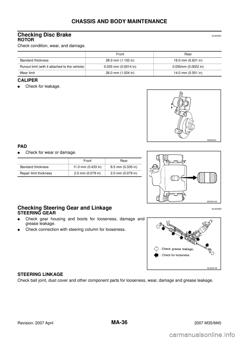
Checking Disc BrakeNLS0008C
ROTOR
Check condition, wear, and damage.
CALIPER
�Check for leakage.
PA D
�Check for wear or damage.
Checking Steering Gear and LinkageNLS0008D
STEERING GEAR
�Check gear housing and boots for looseness, damage and
grease leakage.
�Check connection with steering column for looseness.
STEERING LINKAGE
Check ball joint, dust cover and other component parts for looseness, wear, damage and grease leakage.
Front Rear
Standard thickness 28.0 mm (1.102 in) 16.0 mm (0.631 in)
Runout limit (with it attached to the vehicle) 0.035 mm (0.0014 in) 0.055mm (0.0022 in)
Wear limit 26.0 mm (1.024 in) 14.0 mm (0.551 in)
SMA922A
Front Rear
Standard thickness 11.0 mm (0.433 in) 8.5 mm (0.335 in)
Repair limit thickness 2.0 mm (0.079 in) 2.0 mm (0.079 in)
BRA0010D
SLIA0014E
Page 3838 of 4647

CHASSIS AND BODY MAINTENANCE
MA-39
C
D
E
F
G
H
I
J
K
MA
B
MA
Revision: 2007 April2007 M35/M45
Checking Seat Belt, Buckles, Retractors, Anchors and AdjustersNLS0008I
CAUTION:
�After any collision, inspect all seat belt assemblies, including retractors and other attached hard-
wares (I.e. anchor bolt, guide rail set). Nissan recommends to replace all seat belt assemblies in
use during a collision, unless not damaged and properly operating after minor collision.
Also inspect seat belt assemblies not in use during a collision, and replace if damaged or improp-
erly operating.
Seat belt pre-tensioner should be replaced even if the seat belts are not in use during a frontal col-
lision where the driver and passenger air bags are deployed.
�If any component of seat belt assembly is questionable, do not repair.
Replace as seat belt assembly.
�If webbing is cut, frayed, or damaged, replace belt assembly.
�Never oil tongue and buckle.
�Use a genuine NISSAN seat belt assembly.
For details, refer to SB-32, "
Seat Belt Inspection" in SB section.
�Check anchors for loose mounting
�Check belts for damage
�Check retractor for smooth operation
�Check function of buckles and tongues when buckled and released
PIIB3436E
Page 3842 of 4647

PB-1
PARKING BRAKE SYSTEM
F BRAKES
CONTENTS
C
D
E
G
H
I
J
K
L
M
SECTION PB
A
B
PB
Revision: 2007 April2007 M35/M45
PARKING BRAKE SYSTEM
PREPARATION ........................................................... 2
Commercial Service Tools ........................................ 2
PARKING BRAKE SYSTEM ...................................... 3
On-Vehicle Service ................................................... 3
PEDAL STROKE ................................................... 3
INSPECT COMPONENTS .................................... 3
ADJUSTMENT ...................................................... 3
PARKING BRAKE CONTROL ................................... 4
Components ............................................................. 4
Removal and Installation .......................................... 5
REMOVAL ............................................................. 5
INSTALLATION ..................................................... 5PARKING BRAKE SHOE ........................................... 6
Components ............................................................. 6
Removal and Installation .......................................... 7
REMOVAL ............................................................. 7
INSPECTION AFTER REMOVAL ......................... 7
INSTALLATION ..................................................... 8
SERVICE DATA AND SPECIFICATIONS (SDS) ........ 9
Parking Drum Brake ................................................. 9
Parking Brake Control .............................................. 9
Page 3844 of 4647

PARKING BRAKE SYSTEM
PB-3
C
D
E
G
H
I
J
K
L
MA
B
PB
Revision: 2007 April2007 M35/M45
PARKING BRAKE SYSTEMPFP:36010
On-Vehicle ServiceNFS000SS
PEDAL STROKE
�Operate parking brake pedal with a force of 196 N (20 kg, 44 lb), make sure pedal stroke is within the
specified number of notches. (Check it by listening and counting ratchet clicks.)
INSPECT COMPONENTS
�Make sure that the mounting conditions (looseness, backlash, etc.) of each component are normal.
�Check the following:
–Device assembly for bend, damage and cracks. Replace if there are.
–Cables and equalizer for wear and damage. Replace if there are.
–Parking brake switch. Replace if it does not work correctly.
ADJUSTMENT
�To perform adjustment operations, remove rear tires from vehicle with power tool.
1. Insert a deep socket wrench onto adjusting nut. Rotate adjusting
nut to fully loosen cable, and then release parking brake pedal.
2. Secure disc rotor to hub using wheel nut so as not to tilt disc
rotor.
3. Remove adjuster hole plug installed on the disc rotor. Turn the
adjuster in direction “A” using a flat-bladed screwdriver as
shown, until disc rotor is locked. Turn the adjuster in the oppo-
site direction by 5 or 6 notches after locking.
4. Rotate disc rotor to make sure that there is no drag. Install the
adjuster hole plug.
5. Adjust parking brake cable with the following procedure.
a. Operate parking brake pedal 10 or more times with the force of
full stroke.
b. Rotate adjusting nut to adjust parking brake pedal stroke using a
deep socket wrench.
CAUTION:
Do not reuse adjusting nut after removing it.
c. Operate parking brake pedal with a force of 196 N (20 kg, 44 lb), make sure the pedal stroke is within the
specified number of notches. (Check it by listening and counting ratchet clicks.)
d. Make sure that there is no drag on rear brake with parking brake pedal completely released.Pedal stroke : 3 - 4 notches
SFIA2961E
Pedal stroke : 3 - 4 notches
PFIA0295E
Page 3845 of 4647
PB-4
PARKING BRAKE CONTROL
Revision: 2007 April2007 M35/M45
PARKING BRAKE CONTROLPFP:36010
ComponentsNFS000ST
1. Device assembly 2. Parking brake switch 3. Pedal pad
4. Adjusting nut 5. Stopper rubber 6. Return spring
7. Spring insulator 8. Front cable 9. Equalizer
10. Spring 11. Rear cable (LH) 12. Pin
13. Rear cable (RH) 14. Lock plate
Refer to GI-11, "
Components" and the followings for the symbols in the figure.
: Apply Multi-purpose grease.
SFIA2962E