Page 4152 of 4366

SRS-6
SUPPLEMENTAL RESTRAINT SYSTEM (SRS)
Revision: 2006 July 2007 FX35/FX45
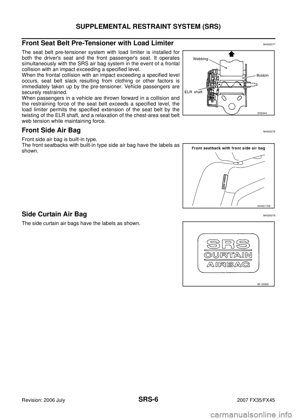
Front Seat Belt Pre-Tensioner with Load LimiterNHS00077
The seat belt pre-tensioner system with load limiter is installed for
both the driver's seat and the front passenger's seat. It operates
simultaneously with the SRS air bag system in the event of a frontal
collision with an impact exceeding a specified level.
When the frontal collision with an impact exceeding a specified level
occurs, seat belt slack resulting from clothing or other factors is
immediately taken up by the pre-tensioner. Vehicle passengers are
securely restrained.
When passengers in a vehicle are thrown forward in a collision and
the restraining force of the seat belt exceeds a specified level, the
load limiter permits the specified extension of the seat belt by the
twisting of the ELR shaft, and a relaxation of the chest-area seat belt
web tension while maintaining force.
Front Side Air BagNHS00078
Front side air bag is built-in type.
The front seatbacks with built-in type side air bag have the labels as
shown.
Side Curtain Air BagNHS00079
The side curtain air bags have the labels as shown.
SRS444
SHIA0170E
BF-2006D
Page 4153 of 4366

SUPPLEMENTAL RESTRAINT SYSTEM (SRS) SRS-7
C
D E
F
G
I
J
K L
M A
B
SRS
Revision: 2006 July 2007 FX35/FX45
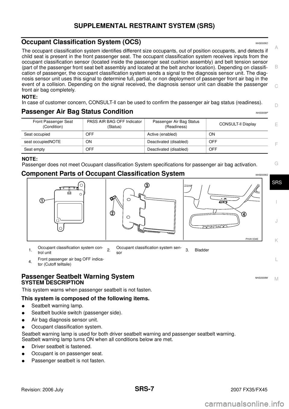
Occupant Classification System (OCS)NHS0009O
The occupant classification system identifies different size occupants, out of position occupants, and detects if
child seat is present in the front passenger seat. The occupant classification system receives inputs from the
occupant classification sensor (located inside the passenger seat cushion assembly) and belt tension sensor
(part of the passenger front seat belt assembly and located at the belt anchor location). Depending on classifi-
cation of passenger, the occupant classification system sends a signal to the diagnosis sensor unit. The diag-
nosis sensor unit uses this signal to determine full, partial, or non deployment of passenger front air bag in the
event of a collision. Depending on the signal received, the diagnosis sensor unit can disable the passenger
front air bag completely.
NOTE:
In case of customer concern, CONSULT-ll can be used to confirm the passenger air bag status (readiness).
Passenger Air Bag Status Condition NHS0009P
NOTE:
Passenger does not meet Ocuupant classification System specifications for passenger air bag activation.
Component Parts of Occupant Classification System NHS0009Q
Passenger Seatbelt Warning System NHS0009W
SYSTEM DESCRIPTION
This system warns when passenger seatbelt is not fasten.
This system is composed of the following items.
�Seatbelt warning lamp.
�Seatbelt buckle switch (passenger side).
�Air bag diagnosis sensor unit.
�Occupant classification system.
Seatbelt warning lamp is used for both driver seatbelt warning and passenger seatbelt warning.
Seatbelt warning lamp turns ON when all conditions below are met.
�Driver seatbelt is fastened.
�Occupant is on passenger seat.
�Passenger seatbelt is not fasten.
Front Passenger Seat (Condition) PASS AIR BAG OFF Indicator
(Status) Passenger Air Bag Status
(Readiness) CONSULT-ll Display
Seat occupied OFF Active (enabled) ON
seat occupiedNOTE ON Deactivated (disabled) OFF
Seat empty OFF Deactivated (disabled) OFF
PHIA1334E
1. Occupant classification system con-
trol unit 2.
Occupant classification system sen-
sor 3. Bladder
4. Front passenger air bag OFF indica-
tor (Cutoff telltaile)
Page 4154 of 4366

SRS-8
TROUBLE DIAGNOSIS
Revision: 2006 July 2007 FX35/FX45
TROUBLE DIAGNOSISPFP:00004
Trouble Diagnosis IntroductionNHS0007A
CAUTION:
�Do not use electrical test equipment on any circuit related to the SRS unless instructed in this Ser-
vice Manual. SRS wiring harnesses can be identified by yellow and/or orange harnesses or har-
ness connectors.
�Do not repair, splice or modify the SRS wiring harness. If the harness is damaged, replace it with a
new one.
�Keep ground portion clean.
DIAGNOSIS FUNCTION
The SRS self-diagnostic results can be read by using “AIR BAG” warning lamp and/or CONSULT-II.
The User mode is exclusively prepared for the customer (driver). This mode warns the driver of a system mal-
function through the operation of the “AIR BAG” warning lamp.
The Diagnosis mode allows the technician to locate and inspect the malfunctioning part.
The mode applications for the “AIR BAG” warning lamp and CONSULT-II are as follows:
HOW TO PERFORM TROUBLE DIAGNOSIS FOR QUICK AND ACCURATE REPAIR
A good understanding of the malfunction conditions can make troubleshooting faster and more accurate.
In general, each customer feels differently about a malfunction. It is important to fully understand the symp-
toms or conditions for a customer complaint.
Information from Customer
WHAT..... Vehicle model
WHEN..... Date, Frequencies
WHERE..... Road conditions
HOW..... Operating conditions, Symptoms
Preliminary Check
Make sure the following parts are in good order.
�Battery (Refer to SC-5, "How to Handle Battery" .)
�Fuse (Refer to SRS-12, "Wiring Diagram — SRS —" .)
�System component-to-harness connections
User mode Diagnosis mode Display type
“AIR BAG” warning lamp X X ON-OFF operation CONSULT-II — X Monitoring
Page 4155 of 4366
TROUBLE DIAGNOSIS SRS-9
C
D E
F
G
I
J
K L
M A
B
SRS
Revision: 2006 July 2007 FX35/FX45
WORK FLOW
*1:SRS-8, "Preliminary Check".*2: SRS-20, "SRS Operation Check".*3:SRS-22, "DIAGNOSTIC PROCE-
DURE 2".
*4: SRS-35, "
DIAGNOSTIC PROCE-
DURE 6". *5
SRS-27, "
DIAGNOSTIC PROCE-
DURE 3". *6
SRS-35, "
DIAGNOSTIC PROCE-
DURE 6".
PHIA0710E
Page 4156 of 4366
SRS-10
TROUBLE DIAGNOSIS
Revision: 2006 July 2007 FX35/FX45
Component Parts LocationNHS0007B
PHIA1352E
1. Driver air bag module 2. Front passenger air bag module 3. Spiral cable
4. Front side air bag module (LH/RH) 5. Diagnosis sensor unit 6. Side air bag (Satellite) sensor (LH/
RH)
7. Seat belt pre-tensioner (LH/RH) 8. Seat belt buckle switch (LH/RH) 9. Side curtain air bag module
10. Crash zone sensor 11. Occupant classification system sen-
sor 12.
Occupant classification system con-
trol unit
13. Belt tension sensor (passenger
side)
Page 4157 of 4366
TROUBLE DIAGNOSIS SRS-11
C
D E
F
G
I
J
K L
M A
B
SRS
Revision: 2006 July 2007 FX35/FX45
SchematicNHS0007C
THWM0250E
Page 4158 of 4366
SRS-12
TROUBLE DIAGNOSIS
Revision: 2006 July 2007 FX35/FX45
Wiring Diagram — SRS —NHS0007D
THWM0255E
Page 4159 of 4366
TROUBLE DIAGNOSIS SRS-13
C
D E
F
G
I
J
K L
M A
B
SRS
Revision: 2006 July 2007 FX35/FX45
THWM0224E