Page 281 of 464

•and a slight drop or fall away of the brake pedal at the
end of the stop.
These are all normal characteristics of ABS.
WARNING!
The Anti-Lock Brake System contains sophisticated
electronic equipment that may be susceptible to
interference caused by improperly installed or high
output radio transmitting equipment. This interfer-
ence can cause possible loss of anti-lock braking
capability. Installation of such equipment should be
performed by qualified professionals.
All vehicle wheels and tires must be the same size and
type and tires must be properly inflated to produce
accurate signals for the computer.
ELECTRONIC STABILITY PROGRAM (ESP)
Your vehicle is equipped with an advanced electronic
brake control system that includes ABS (Anti-Lock Brake
System), TCS (Traction Control System), BAS (Brake
Assist System), ERM (Electronic Roll Mitigation) and ESP
(Electronic Stability Program). All systems work together
to enhance vehicle stability and control in various driving
conditions and are commonly referred to as ESP.
TheESPsystem enhances directional control and stabil-
ity of the vehicle under various driving conditions. ESP
corrects for over/under steering of the vehicle by apply-
ing the brake of the appropriate wheel to assist in
counteracting the over/under steer condition. Engine
power may also be reduced to help the vehicle maintain
the desired path. ESP uses sensors in the vehicle to
determine the vehicle path intended by the driver and
compares it to the actual path of the vehicle. When the
actual path does not match the intended path, ESP
STARTING AND OPERATING 281
5
Page 282 of 464

applies the brake of the appropriate wheel to assist in
counteracting the Over-steer or Under-steer condition.
•Over-steer: when the vehicle is turning more than
appropriate for the steering wheel position.
•Under-steer: when the vehicle is turning less than
appropriate for the steering wheel position.
The “ESP/TCS Indicator Light” located in the instrument
cluster, starts to flash as soon as the tires lose traction and
the ESP system becomes active. The “ESP/TCS Indicator
Light” also flashes when TCS is active. If the “ESP/TCS
Indicator Light” begins to flash during acceleration, ease
up on the accelerator and apply as little throttle as
possible. Be sure to adapt your speed and driving to the
prevailing road conditions.
WARNING!
Electronic Stability Program (ESP) cannot prevent
the natural laws of physics from acting on the
vehicle, nor can it increase the traction afforded by
prevailing road conditions. ESP cannot prevent acci-
dents, including those resulting from excessive
speed in turns, driving on very slippery surfaces, or
hydroplaning. Only a safe, attentive, and skillful
driver can prevent accidents. The capabilities of an
ESP-equipped vehicle must never be exploited in a
reckless or dangerous manner which could jeopar-
dize the user’s safety or the safety of others.
282 STARTING AND OPERATING
Page 283 of 464

ESP has the following operating modes:
•
ESP OnThis is the normal operating mode for ESP.
Whenever the vehicle is started the ESP system will be
in this mode. This mode should be used for almost all
driving situations. ESP should only be turned to
“Partial Off” for specific reasons as noted below.
•Partial OffThis mode is entered by momentarily
depressing the “ESP Control Switch”. When in “Partial
Off” mode, the TCS portion of ESP, except for the
“limited slip” feature described in the TCS section, has
been disabled and the “ESP/TCS Indicator Light” will
be illuminated. All other stability features of ESP
function normally, with the exception of engine power
reduction. This mode is intended to be used if the
vehicle is in deep snow, sand or gravel conditions and
more wheel spin than ESP would normally allow isrequired to gain traction. To turn ESP on again, mo-
mentarily depress the “ESP Control Switch”. This will
restore the normal “ESP On” mode of operation.
NOTE:To improve the vehicle’s traction when driving
with snow chains, or starting off in deep snow, sand or
gravel, it may be desirable to switch to the “Partial Off”
mode by pressing the ESP switch. Once the situation
requiring ESP to be switched to the “Partial Off” mode is
overcome, turn ESP back on by momentarily depressing
the “ESP Control Switch”. This may be done while the
vehicle is in motion.
ESP/BAS Warning Lamp and ESP/TCS Indicator
Light
The malfunction indicator for the ESP is combined with
the BAS indicator. The yellow “ESP/BAS Warning
Lamp” and the yellow “ESP/TCS Indicator Light” in the
instrument cluster both come on when the ignition
switch is turned to the “ON” position. They should both
STARTING AND OPERATING 283
5
Page 284 of 464

go out with the engine running. If the “ESP/BAS Warn-
ing Lamp” comes on continuously with the engine
running, a malfunction has been detected in either the
ESP or BAS system, or both. If this light remains on after
several ignition cycles, and the vehicle has been driven
several miles at speeds greater than 30 mph (48 km/h),
see your authorized dealer as soon as possible to have the
problem diagnosed and corrected.
NOTE:
•The “ESP Indicator Light” and the “ESP/BAS Warning
Lamp” come on momentarily each time the ignition
switch is turned ON.
•Each time the ignition is turned ON, the ESP System
will be ON even if it was turned off previously.
•The ESP Control System will make buzzing or clicking
sounds when it is active. This is normal; the sounds
will stop when ESP becomes inactive following the
maneuver that caused the ESP activation.
Brake Assist System (BAS)
The BAS is designed to optimize the vehicle’s braking
capability during emergency braking maneuvers. The
system detects an emergency braking situation by sens-
ing the rate and amount of brake application and then
applies optimum pressure to the brakes. This can help
reduce braking distances. The BAS complements the
Anti-lock Brake System (ABS). Applying the brakes very
quickly results in the best BAS assistance. To receive the
benefit of the system, you must apply continuous brak-
ing pressure during the stopping sequence. Do not
reduce brake pedal pressure unless braking is no longer
desired. Once the brake pedal is released, the BAS is
deactivated.
284 STARTING AND OPERATING
Page 289 of 464
•European Metric tire sizing is based on European
design standards. Tires designed to this standard have
the tire size molded into the sidewall beginning with
the section width. The letter�P�is absent from this tire
size designation. Example: 215/65R15 96H
•LT (Light Truck)-Metric tire sizing is based on U.S.
design standards. The size designation for LT-Metric
tires is the same as for P-Metric tires except for the
letters “LT” that are molded into the sidewall preced-
ing the size designation. Example: LT235/85R16.
•Temporary Spare tires are high-pressure compact
spares designed for temporary emergency use only.
Tires designed to this standard have the letter “T”
molded into the sidewall preceding the size designa-
tion. Example: T145/80D18 103M.
•High Flotation tire sizing is based on U.S. design
standards and it begins with the tire diameter molded
into the sidewall. Example: 31x10.5 R15 LT.
STARTING AND OPERATING 289
5
Page 290 of 464
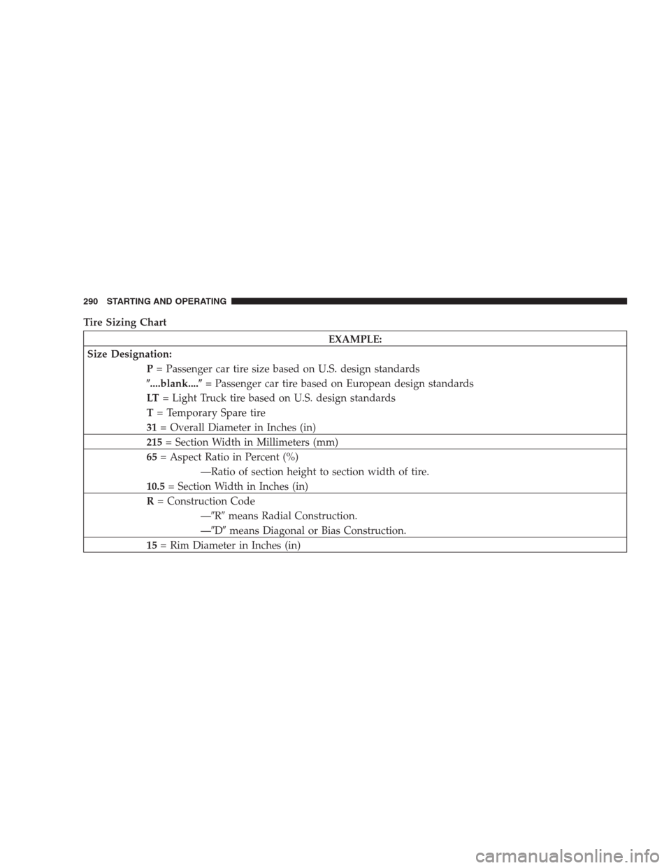
Tire Sizing Chart
EXAMPLE:
Size Designation:
P= Passenger car tire size based on U.S. design standards
�....blank....�= Passenger car tire based on European design standards
LT= Light Truck tire based on U.S. design standards
T= Temporary Spare tire
31= Overall Diameter in Inches (in)
215= Section Width in Millimeters (mm)
65= Aspect Ratio in Percent (%)
—Ratio of section height to section width of tire.
10.5= Section Width in Inches (in)
R= Construction Code
—�R�means Radial Construction.
—�D�means Diagonal or Bias Construction.
15= Rim Diameter in Inches (in)
290 STARTING AND OPERATING
Page 291 of 464
EXAMPLE:
Service Description:
95= Load Index
—A numerical code associated with the maximum load a tire can carry.
H= Speed Symbol
—A symbol indicating the range of speeds at which a tire can carry a load corresponding
to its load index under certain operating conditions.
—The maximum speed corresponding to the Speed Symbol should only be achieved un-
der specified operating conditions. (i.e. tire pressure, vehicle loading, road conditions,
and posted speed limits).
Load Identification:
�....blank....�= Absence of any text on sidewall of the tire indicates a Standard Load (SL) Tire
Extra Load (XL)= Extra Load (or Reinforced) Tire
Light Load= Light Load Tire
C,D,E= Load range associated with the maximum load a tire can carry at a specified pressure
Maximum Load— Maximum Load indicates the maximum load this tire is designed to carry.
Maximum Pressure— Maximum Pressure indicates the maximum permissible cold tire inflation pressure for this
tire.
STARTING AND OPERATING 291
5
Page 304 of 464

Life of Tire
The service life of a tire is dependent upon varying
factors including but not limited to:
•Driving style
•Tire pressure
•Distance driven
WARNING!
Tires and spare tire should be replaced after six
years, regardless of the remaining tread. Failure to
follow this warning can result in sudden tire failure.
You could lose control and have an accident result-
ing in serious injury or death.
Keep dismounted tires in a cool, dry place with as little
exposure to light as possible. Protect tires from contact
with oil, grease, and gasoline.
Replacement Tires
The tires on your new vehicle provide a balance of many
characteristics. They should be inspected regularly for
wear and correct cold tire inflation pressure. The manu-
facturer strongly recommends that you use tires equiva-
lent to the originals in size, quality and performance
when replacement is needed (refer to the paragraph on
“Tread Wear Indicators”). Refer to the “Tire and Loading
Information” placard for the size designation of your tire.
The service description and load identification will be
found on the original equipment tire. Failure to use
equivalent replacement tires may adversely affect the
safety, handling, and ride of your vehicle. We recommend
that you contact your original equipment or an autho-
rized tire dealer with any questions you may have on tire
specifications or capability.
304 STARTING AND OPERATING