Page 70 of 464

and use the lap belt. Never allow a child to put the
shoulder belt under an arm or behind their back.
NOTE:For additional information, refer to
www.seatcheck.org or call 1-866-SEATCHECK.
WARNING!
•Improper installation can lead to failure of an
infant or child restraint. It could come loose in a
collision. The child could be badly injured or
killed. Follow the manufacturer’s directions ex-
actly when installing an infant or child restraint.
•A rearward facing child restraint should only be
used in a rear seat. A rearward facing child re-
straint in the front seat may be struck by a
deploying passenger airbag which may cause se-
vere or fatal injury to the infant.
Here are some tips on getting the most out of your child
restraint:
•Before buying any restraint system, make sure that it
has a label certifying that it meets all applicable Safety
Standards. We also recommend that you make sure
that you can install the child restraint in the vehicle
where you will use it, before you buy it.
•The restraint must be appropriate for your child’s
weight and height. Check the label on the restraint for
weight and height limits.
•Carefully follow the instructions that come with the
restraint. If you install the restraint improperly, it may
not work when you need it.
The passenger seat belts are equipped with cinching
latch plates, which are designed to keep the lap
portion tight around the child restraint so that it is not
necessary to use a locking clip. Pulling up on the
70 THINGS TO KNOW BEFORE STARTING YOUR VEHICLE
Page 172 of 464
LOAD LEVELING SYSTEM
The automatic load leveling system will provide a level
riding vehicle under most passenger and cargo loading
conditions.
A hydraulic pump contained within the shock absorbers
raises the rear of the vehicle to the correct height. It takes
approximately 1 mile (1.6 km) of driving for the leveling
to complete depending on road surface conditions.If the leveled vehicle is not moved for approximately 15
hours, the leveling system will bleed itself down. The
vehicle must be driven to reset the system.
172 UNDERSTANDING THE FEATURES OF YOUR VEHICLE
Page 200 of 464

ELECTRONIC DIGITAL CLOCK
The clock and radio each use the display panel built into
the radio. A digital readout shows the time in hours and
minutes whenever the ignition switch is in the ON or
ACC position and the time button is pressed.
When the ignition switch is in the OFF position, or when
the radio frequency is being displayed, time keeping is
accurately maintained.
Clock Setting Procedure
1. Turn the ignition switch to the ON or ACC position
and press the time button. Using the tip of a ballpoint pen
or similar object, press either the hour (H) or minute (M)
buttons on the radio.
2. Press the H button to set hours or the M button to set
minutes. The time setting will increase each time you
press a button.
RADIO GENERAL INFORMATION
Radio Broadcast Signals
Your new radio will provide excellent reception under
most operating conditions. Like any system, however, car
radios have performance limitations, due to mobile op-
eration and natural phenomena, which might lead you to
believe your sound system is malfunctioning. To help
you understand and save you concern about these “ap-
parent” malfunctions, you must understand a point or
two about the transmission and reception of radio sig-
nals.
Two Types of Signals
There are two basic types of radio signals... AM or
Amplitude Modulation, in which the transmitted sound
causes the amplitude, or height, of the radio waves to
vary... and FM or Frequency Modulation, in which the
frequency of the wave is varied to carry the sound.
200 UNDERSTANDING YOUR INSTRUMENT PANEL
Page 290 of 464
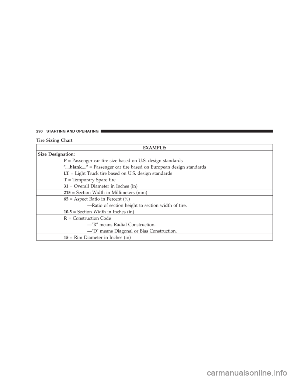
Tire Sizing Chart
EXAMPLE:
Size Designation:
P= Passenger car tire size based on U.S. design standards
�....blank....�= Passenger car tire based on European design standards
LT= Light Truck tire based on U.S. design standards
T= Temporary Spare tire
31= Overall Diameter in Inches (in)
215= Section Width in Millimeters (mm)
65= Aspect Ratio in Percent (%)
—Ratio of section height to section width of tire.
10.5= Section Width in Inches (in)
R= Construction Code
—�R�means Radial Construction.
—�D�means Diagonal or Bias Construction.
15= Rim Diameter in Inches (in)
290 STARTING AND OPERATING
Page 331 of 464

The downward force exerted on the hitch ball by the
trailer. In most cases it should not be less than 10% or
more than 15% of the trailer load. You must consider this
as part of the")
Tongue Weight (TW)
The downward force exerted on the hitch ball by the
trailer. In most cases it should not be less than 10% or
more than 15% of the trailer load. You must consider this
as part of the load on your vehicle.
Frontal Area
The maximum height and maximum width of the front of
a trailer.
Trailer Sway Control
The trailer sway control is a telescoping link that can be
installed between the hitch receiver and the trailer tongue
that typically provides adjustable friction associated with
the telescoping motion to dampen any unwanted trailer
swaying motions while traveling.
Weight-Carrying Hitch
A weight-carrying hitch supports the trailer tongue
weight, just as if it were luggage located at a hitch ball or
some other connecting point of the vehicle. These kind ofhitches are the most popular on the market today and
they’re commonly used to tow small- and medium-sized
trailers.
Weight-Distributing Hitch
A weight-distributing system works by applying lever-
age through spring (load) bars. They are typically used
for heavier loads, to distribute trailer tongue weight to
the tow vehicle’s front axle and the trailer axle(s). When
used in accordance with the manufacturers’ directions, it
provides for a more level ride, offering more consistent
steering and brake control thereby enhancing towing
safety. The addition of a friction / hydraulic sway control
also dampens sway caused by traffic and crosswinds and
contributes positively to tow vehicle and trailer stability.
Trailer sway control and a weight distributing (load
equalizing) hitch are recommended for heavier Tongue
Weights (TW) and may be required depending on Vehicle
and Trailer configuration / loading to comply with gross
axle weight rating (GAWR) requirements.
STARTING AND OPERATING 331
5