Page 375 of 2000
AX–138U241E AUTOMATIC TRANSAXLE – FLOOR SHIFT ASSEMBLY
AX
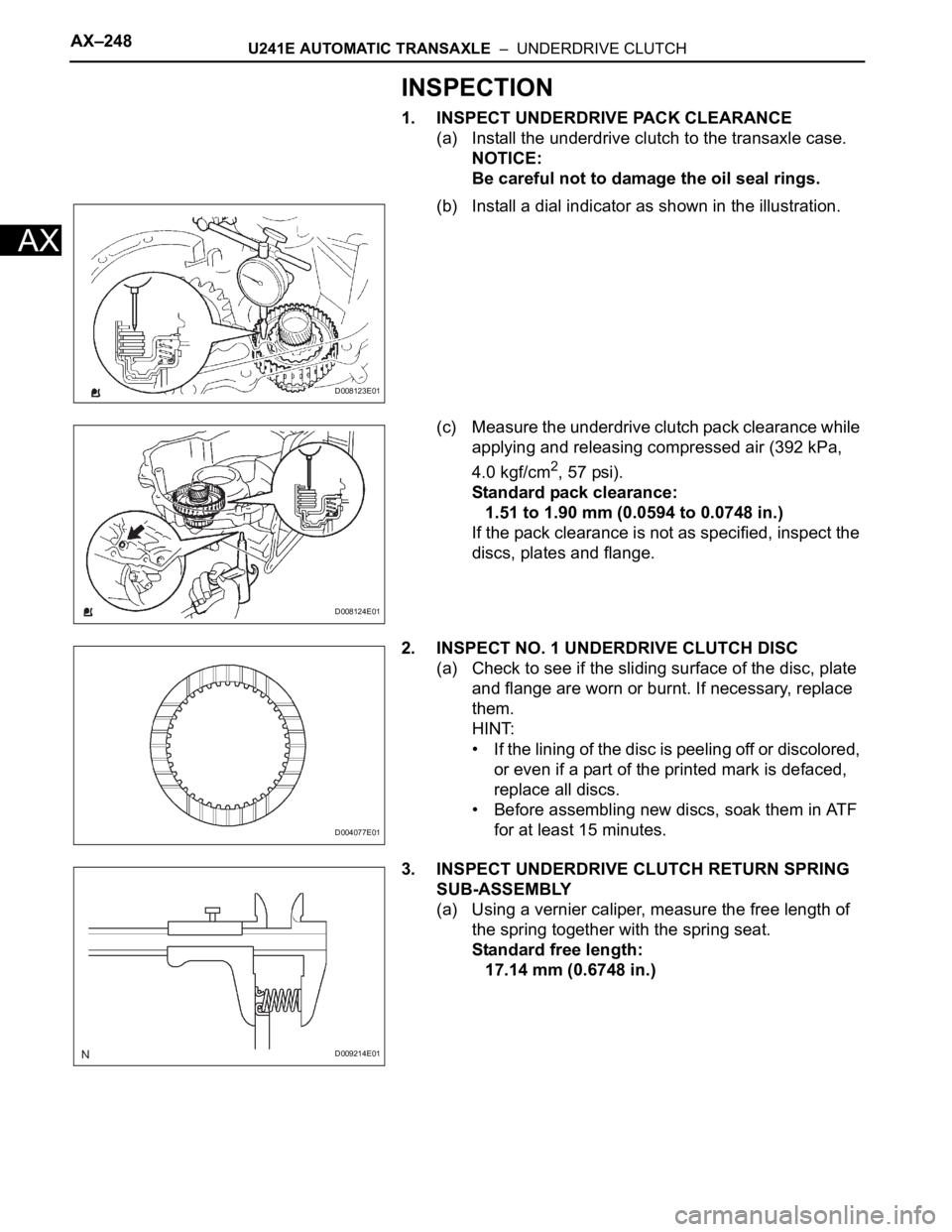
4. REMOVE SHIFT LOCK RELEASE BUTTON
(a) Detach the 2 claws and remove the button and
spring from the position indicator light housing.
C127817
Page 376 of 2000

AX–248U241E AUTOMATIC TRANSAXLE – UNDERDRIVE CLUTCH
AX
INSPECTION
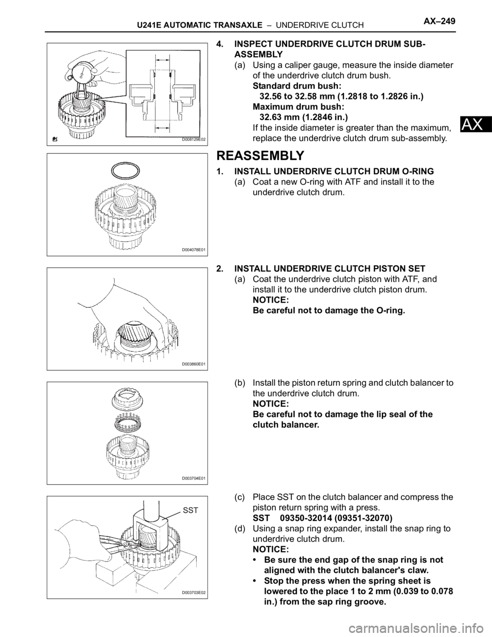
1. INSPECT UNDERDRIVE PACK CLEARANCE
(a) Install the underdrive clutch to the transaxle case.
NOTICE:
Be careful not to damage the oil seal rings.
(b) Install a dial indicator as shown in the illustration.
(c) Measure the underdrive clutch pack clearance while
applying and releasing compressed air (392 kPa,
4.0 kgf/cm
2, 57 psi).
Standard pack clearance:
1.51 to 1.90 mm (0.0594 to 0.0748 in.)
If the pack clearance is not as specified, inspect the
discs, plates and flange.
2. INSPECT NO. 1 UNDERDRIVE CLUTCH DISC
(a) Check to see if the sliding surface of the disc, plate
and flange are worn or burnt. If necessary, replace
them.
HINT:
• If the lining of the disc is peeling off or discolored,
or even if a part of the printed mark is defaced,
replace all discs.
• Before assembling new discs, soak them in ATF
for at least 15 minutes.
3. INSPECT UNDERDRIVE CLUTCH RETURN SPRING
SUB-ASSEMBLY
(a) Using a vernier caliper, measure the free length of
the spring together with the spring seat.
Standard free length:
17.14 mm (0.6748 in.)
D008123E01
D008124E01
D004077E01
D009214E01
Page 377 of 2000

U241E AUTOMATIC TRANSAXLE – UNDERDRIVE CLUTCHAX–249
AX
4. INSPECT UNDERDRIVE CLUTCH DRUM SUB-
ASSEMBLY
(a) Using a caliper gauge, measure the inside diameter
of the underdrive clutch drum bush.
Standard drum bush:
32.56 to 32.58 mm (1.2818 to 1.2826 in.)
Maximum drum bush:
32.63 mm (1.2846 in.)
If the inside diameter is greater than the maximum,
replace the underdrive clutch drum sub-assembly.
REASSEMBLY
1. INSTALL UNDERDRIVE CLUTCH DRUM O-RING
(a) Coat a new O-ring with ATF and install it to the
underdrive clutch drum.
2. INSTALL UNDERDRIVE CLUTCH PISTON SET
(a) Coat the underdrive clutch piston with ATF, and
install it to the underdrive clutch piston drum.
NOTICE:
Be careful not to damage the O-ring.
(b) Install the piston return spring and clutch balancer to
the underdrive clutch drum.
NOTICE:
Be careful not to damage the lip seal of the
clutch balancer.
(c) Place SST on the clutch balancer and compress the
piston return spring with a press.
SST 09350-32014 (09351-32070)
(d) Using a snap ring expander, install the snap ring to
underdrive clutch drum.
NOTICE:
• Be sure the end gap of the snap ring is not
aligned with the clutch balancer's claw.
• Stop the press when the spring sheet is
lowered to the place 1 to 2 mm (0.039 to 0.078
in.) from the sap ring groove.
D008129E02
D004078E01
D003860E01
D003704E01
D003703E02
Page 378 of 2000

AX–250U241E AUTOMATIC TRANSAXLE – UNDERDRIVE CLUTCH
AX
• This prevents the spring sheet from being
deformed.
• Do not expand the snap ring excessively.
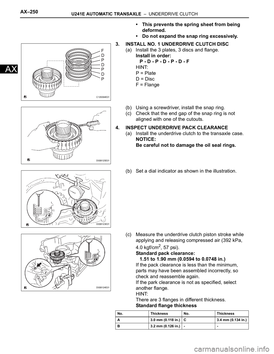
3. INSTALL NO. 1 UNDERDRIVE CLUTCH DISC
(a) Install the 3 plates, 3 discs and flange.
Install in order:
P - D - P - D - P - D - F
HINT:
P = Plate
D = Disc
F = Flange
(b) Using a screwdriver, install the snap ring.
(c) Check that the end gap of the snap ring is not
aligned with one of the cutouts.
4. INSPECT UNDERDRIVE PACK CLEARANCE
(a) Install the underdrive clutch to the transaxle case.
NOTICE:
Be careful not to damage the oil seal rings.
(b) Set a dial indicator as shown in the illustration.
(c) Measure the underdrive clutch piston stroke while
applying and releasing compressed air (392 kPa,
4.0 kgf/cm
2, 57 psi).
Standard pack clearance:
1.51 to 1.90 mm (0.0594 to 0.0748 in.)
If the pack clearance is less than the minimum,
parts may have been assembled incorrectly, so
check and reassemble again.
If the park clearance is not as specified, select
another flange.
HINT:
There are 3 flanges in different thickness.
Standard flange thickness
C129394E01
D008125E01
D008123E01
D008124E01
No. Thickness No. Thickness
A 3.0 mm (0.118 in.) C 3.4 mm (0.134 in.)
B 3.2 mm (0.126 in.) - -
Page 386 of 2000

SERVICE SPECIFICATIONS – U151F AUTOMATIC TRANSMISSIONSS–53
SS
TORQUE SPECIFICATIONS
Automatic Transaxle Assembly
Part Tightened N*m kgf*cm ft*lbf
Park/neutral position switch Nut 6.9 70 61 in.*lbf
Bolt 5.4 55 48 in.*lbf
Control shaft lever x Control shaft 13 133 10
Shift control cable x Control shaft lever 15 153 11
Transaxle housing x Engine block Upper side
bolt64 653 47
Lower side
bolt A37 377 27
Lower side
bolt B46 470 34
Torque converter clutch x Drive plate 41 418 30
Flywheel housing under cover x Automatic transaxle 7.8 80 69 in.*lbf
Front engine mounting bracket x Transaxle 64 653 47
Rear engine mounting bracket x Transaxle 45 459 33
Engine mounting bracket LH x Transaxle 64 653 47
Oil filler tube x Transaxle
Oil filler tube x Front engine mounting bracket5.5 56 49 in.*lbf
Control cable bracket No. 1 x Transaxle 12 122 9
Control cable bracket No. 2 x Transaxle 12 122 9
Oil cooler inlet elbow x Transaxle 27 276 20
Oil cooler outlet elbow x Transaxle 27 276 20
Starter x Transaxle37 377 27
Starter wire x Starter9.8 100 88 in.*lbf
Speed sensor (NC) x Transaxle11 11 2 8
Speed sensor (NT) x Transaxle11 11 2 8
Drain plug x Oil pan47 479 35
Transmission wire x Transaxle5.4 55 48 in.*lbf
ATF temperature sensor x Valve body 6.6 67 58 in.*lbf
Oil pan x Transaxle7.8 80 69 in.*lbf
Solenoid valve x Valve body SL2, DSL,
S411 11 0 8
SL1, SL3 6.6 67 58 in.*lbf
Valve body x Transaxle11 11 2 8
Oil strainer x Valve body11 11 2 8
Floor shift assembly x Body12 122 9
Control cable clamp x Engine mounting insulator 12 122 9
Differential gear lube apply tube x Transaxle housing 9.8 100 87 in.*lbf
Front planetary gear lock nut280 3,355 207
Brake apply tube clamp x Transaxle case 5.4 55 48 in.*lbf
Transaxle case No. 1 plug x Transaxle rear cover 7.4 75 65 in.*lbf
Transaxle rear cover x Transaxle case Bolt A 19 194 14
Other bolt 25 255 18
Parking lock pawl shaft x Transaxle case 9.8 100 87 in.*lbf
Oil pump assembly x Transaxle case 22 226 16
Transaxle housing x Transaxle case Bolt A 22 254 16
Bolt B 29 295 21
Bolt C 29 295 21
Bolt D 22 254 16
Automatic transmission case plug x Transaxle housing 7.4 75 65 in.*lbf
Page 387 of 2000
SS–54SERVICE SPECIFICATIONS – U151F AUTOMATIC TRANSMISSION
SS
Automatic transmission case plug x Transaxle case 7.4 75 65 in.*lbf
Parking lock pawl bracket x Transaxle case 20 205 15
Manual detent spring x Transaxle case Bolt A 20 205 15
Bolt B 12 120 9
Automatic transaxle oil pan sub-assembly x Transaxle case 7.6 77 67 in.*lbf
Speed sensor x Transaxle case11 11 2 8
Park/neutral start switch x Control shaft lever 13 130 9
Speedometer driven hole cover sub-assembly x Transaxle case 5.5 56 49 in.*lbf
Oil pump body x Stator shaft assembly 9.8 100 87 in.*lbf
Front differential case x Front differential ring gear 95 969 70Part Tightened N*m kgf*cm ft*lbf
Page 388 of 2000

SERVICE SPECIFICATIONS – U140F AUTOMATIC TRANSAXLESS–59
SS
TORQUE SPECIFICATIONS
Automatic Transaxle Assembly
Automatic Transaxle Unit
Part Tightened N*m kgf*cm ft.*lbf
Park/neutral position switch Nut 6.9 70 61 in.*lbf
Bolt 5.4 55 48 in.*lbf
Control shaft lever x Control shaft 12.7 130 9
Shift control cable x Control shaft lever 15 153 11
Transaxle housing x Engine block A bolt 64 653 47
B bolt 46 470 34
Lower side bolt 37 377 27
Torque converter clutch x Drive plate 41 418 30
Engine mounting bracket FR x Transaxle 64 653 47
Oil filler tube x Transaxle 5.5 56 49 in.*lbf
Control cable bracket No.1 x Transaxle 12 122 9
Oil cooler tube clamp x Control cable bracket 5.4 55 48 in.*lbf
Oil cooler inlet tube x Transaxle 34 347 25
Oil cooler outlet tube x Transaxle 34 347 25
Starter x Transaxle37 377 27
Wire harness x Transaxle 13 133 10
Speed sensor (NC) x Transaxle 11 115 8
Speed sensor (NT) x Transaxle 11 112 8
Air cleaner x No. 1 air cleaner inlet 5.0 51 44 in.*lbf
Drain plug x Oil pan47 479 35
Transmission wire x Transaxle 5.4 55 48 in.*lbf
ATF temperature sensor x Valve body 6.6 67 58 in.*lbf
Oil pan x Transaxle7.6 77 67 in.*lbf
Solenoid valve x Valve body Bolt A 6.6 67 58 in.*lbf
Bolt B 11 110 8
Valve body x Transaxle 10.8 110 8
Oil strainer x Valve body 11 110 8
Floor shift assembly x Body 12 120 9
Control cable x Body5.0 51 44 in.*lbf
Transfer x Transaxle69 704 51
Engine mount bracket RR x Transfer stiffener, plate RH 45 459 34
Part Tightened N*m kgf*cm ft.*lbf
Differential gear lube apply tube x Transaxle housing 9.8 100 7
Front planetary gear lock nut 268 2,732 198
Brake apply tube clamp x Transaxle case 5.4 55 48 in.*lbf
Transaxle case No. 1 plug x Transaxle rear cover 7.4 75 65 in.*lbf
Transaxle rear cover plate x transaxle rear cover sub-assembly 7.5 76 66 in.*lbf
Transaxle rear cover x Transaxle case Bolt A 18.6 190 14
Other bolt 24.5 250 18
Pawl shaft clamp x Transaxle case 9.8 100 7
Oil pump assembly x Transaxle case 22 226 16
Transaxle housing x Transaxle case Bolt A 22.1 225 16.3
Bolt B, C 29.4 300 21.7
Transaxle case No. 1 plug x Transaxle housing 7.4 75 65 in.*lbf
Parking lock pawl bracket x Transaxle case 20 205 15
Page 389 of 2000

SS–60SERVICE SPECIFICATIONS – U140F AUTOMATIC TRANSAXLE
SS
Detent spring x Transaxle case Bolt A 20 205 15
Bolt B 12 120 9
Solenoid wire retaining bolt x Transaxle housing 5.4 55 48 in.*lbf
Transmission valve body x Transaxle case 11 110 8
ATF temperature sensor clamp x Valve body 6.6 67 58 in.*lbf
Valve body oil strainer x Transmission valve 11 110 8
Automatic transaxle oil pan sub-assembly x Transaxle case 7.8 80 69 in.*lbf
Speed sensor x Transaxle case 11.3 115 8
Transmission revolution sensor x Transaxle case 11.3 115 8
Oil cooler tube union x Transaxle case 27 276 20
Oil cooler tube union x Transaxle case 27 280 20
Speedometer driven hole cover sub-assembly x Transaxle case 7.0 7061
Oil pump body x Stator shaft assembly 9.8 100 7
Under drive planetary gear x Lock nut 280 2,855 207
Line pressure control solenoid assembly x Transmission valve body assembly 11 110 8
No. 1 clutch control solenoid assembly x Transmission valve body a s s e m b l y 11 11 0 8
Automatic transmission 3 way solenoid assembly x Transmission valve body assembly 11 110 8
No. 2 clutch control solenoid assembly x Transmission valve body a s s e m b l y 11 11 0 8
No. 2 transmission 3 way solenoid assembly x Transmission valve body assembly 11 110 8
Front differential case x Front differential ring gear 95.1 970 70Part Tightened N*m kgf*cm ft.*lbf