Page 359 of 2000
AX–4U151F AUTOMATIC TRANSAXLE – AUTOMATIC TRANSAXLE SYSTEM
AX
PARTS LOCATION
C127571E01
Page 360 of 2000
U151F AUTOMATIC TRANSAXLE – AUTOMATIC TRANSAXLE SYSTEMAX–5
AX
C136232E03
Page 361 of 2000
AX–162U151F AUTOMATIC TRANSAXLE – FLOOR SHIFT ASSEMBLY
AX
REMOVAL
1. DISCONNECT CABLE FROM NEGATIVE BATTERY
TERMINAL
CAUTION:
Wait at least 90 seconds after disconnecting the
cable from the negative (-) battery terminal to
prevent airbag and seat belt pretensioner activation.
2. REMOVE SHIFT LEVER KNOB SUB-ASSEMBLY
3. REMOVE REAR CONSOLE BOX SUB-ASSEMBLY
(a) Remove the console box (see page IP-20).
4. DISCONNECT TRANSMISSION CONTROL CABLE
ASSEMBLY
(a) Disconnect the control cable from the shift lever.
(b) Turn the nut and disconnect the control cable from
the shift lever retainer.
5. REMOVE FLOOR SHIFT ASSEMBLY
(a) Remove the 4 bolts and floor shift.
C130920
C127813E01
C127815
Page 362 of 2000
U151F AUTOMATIC TRANSAXLE – FLOOR SHIFT ASSEMBLYAX–163
AX
(b) Disconnect the 2 connectors and detach the clamp.
DISASSEMBLY
1. REMOVE LOWER POSITION INDICATOR HOUSING
(a) Detach the 4 claws and remove the housing.
(b) Remove the position indicator slide cover with slide
No. 2 cover.
2. REMOVE POSITION INDICATOR LIGHT HOUSING
(a) Detach the 2 claws and remove the indicator light
housing from the floor shift position indicator
housing.
3. REMOVE INDICATOR LIGHT WIRE SUB-ASSEMBLY
C127814
C127818
C127816
Page 363 of 2000
AX–164U151F AUTOMATIC TRANSAXLE – FLOOR SHIFT ASSEMBLY
AX
4. REMOVE SHIFT LOCK RELEASE BUTTON
(a) Detach the 2 claws and remove the button and
spring from the position indicator light housing.
C127817
Page 364 of 2000

AX–288U151F AUTOMATIC TRANSAXLE – DIFFERENTIAL CASE
AX
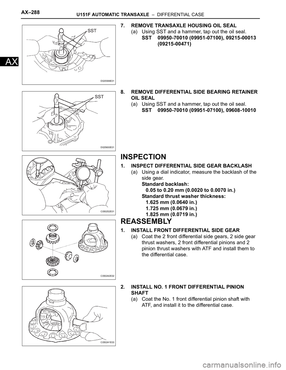
7. REMOVE TRANSAXLE HOUSING OIL SEAL
(a) Using SST and a hammer, tap out the oil seal.
SST 09950-70010 (09951-07100), 09215-00013
(09215-00471)
8. REMOVE DIFFERENTIAL SIDE BEARING RETAINER
OIL SEAL
(a) Using SST and a hammer, tap out the oil seal.
SST 09950-70010 (09951-07100), 09608-10010
INSPECTION
1. INSPECT DIFFERENTIAL SIDE GEAR BACKLASH
(a) Using a dial indicator, measure the backlash of the
side gear.
Standard backlash:
0.05 to 0.20 mm (0.0020 to 0.0070 in.)
Standard thrust washer thickness:
1.625 mm (0.0640 in.)
1.725 mm (0.0679 in.)
1.825 mm (0.0719 in.)
REASSEMBLY
1. INSTALL FRONT DIFFERENTIAL SIDE GEAR
(a) Coat the 2 front differential side gears, 2 side gear
thrust washers, 2 front differential pinions and 2
pinion thrust washers with ATF and install them to
the differential case.
2. INSTALL NO. 1 FRONT DIFFERENTIAL PINION
SHAFT
(a) Coat the No. 1 front differential pinion shaft with
ATF, and install it to the differential case.
D025599E01
D025600E01
C050252E01
C050242E02
C050241E03
Page 365 of 2000

U151F AUTOMATIC TRANSAXLE – DIFFERENTIAL CASEAX–289
AX
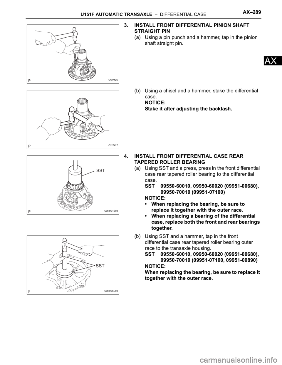
3. INSTALL FRONT DIFFERENTIAL PINION SHAFT
STRAIGHT PIN
(a) Using a pin punch and a hammer, tap in the pinion
shaft straight pin.
(b) Using a chisel and a hammer, stake the differential
case.
NOTICE:
Stake it after adjusting the backlash.
4. INSTALL FRONT DIFFERENTIAL CASE REAR
TAPERED ROLLER BEARING
(a) Using SST and a press, press in the front differential
case rear tapered roller bearing to the differential
case.
SST 09550-60010, 09950-60020 (09951-00680),
09950-70010 (09951-07100)
NOTICE:
• When replacing the bearing, be sure to
replace it together with the outer race.
• When replacing a bearing of the differential
case, replace both the front and rear bearings
together.
(b) Using SST and a hammer, tap in the front
differential case rear tapered roller bearing outer
race to the transaxle housing.
SST 09550-60010, 09950-60020 (09951-00680),
09950-70010 (09951-07100, 09951-00890)
NOTICE:
When replacing the bearing, be sure to replace it
together with the outer race.
C127426
C127427
C083734E02
C083736E03
Page 366 of 2000

AX–290U151F AUTOMATIC TRANSAXLE – DIFFERENTIAL CASE
AX
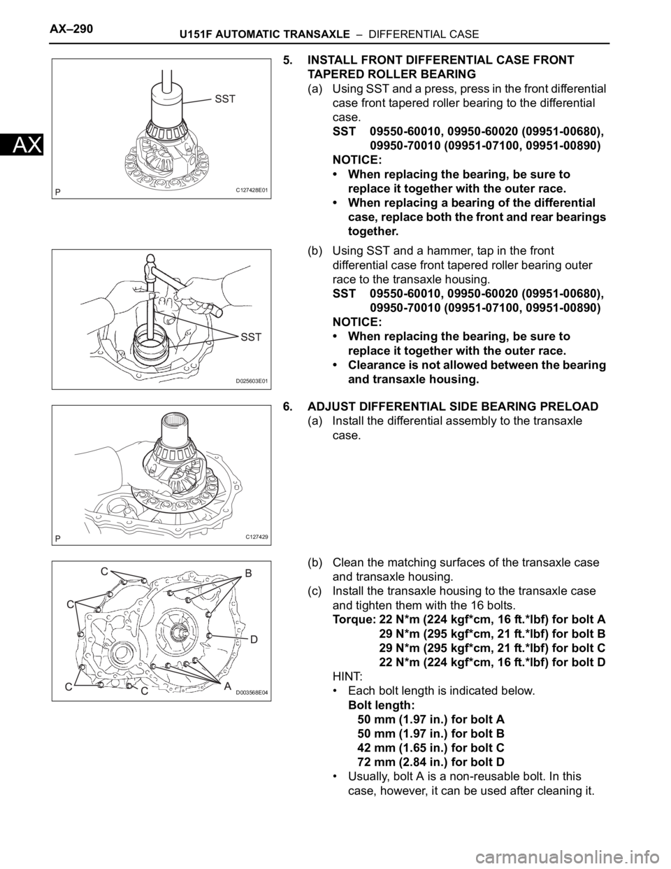
5. INSTALL FRONT DIFFERENTIAL CASE FRONT
TAPERED ROLLER BEARING
(a) U si ng SST and a pres s, pr es s in the f ron t di fferent ial
case front tapered roller bearing to the differential
case.
SST 09550-60010, 09950-60020 (09951-00680),
09950-70010 (09951-07100, 09951-00890)
NOTICE:
• When replacing the bearing, be sure to
replace it together with the outer race.
• When replacing a bearing of the differential
case, replace both the front and rear bearings
together.
(b) Using SST and a hammer, tap in the front
differential case front tapered roller bearing outer
race to the transaxle housing.
SST 09550-60010, 09950-60020 (09951-00680),
09950-70010 (09951-07100, 09951-00890)
NOTICE:
• When replacing the bearing, be sure to
replace it together with the outer race.
• Clearance is not allowed between the bearing
and transaxle housing.
6. ADJUST DIFFERENTIAL SIDE BEARING PRELOAD
(a) Install the differential assembly to the transaxle
case.
(b) Clean the matching surfaces of the transaxle case
and transaxle housing.
(c) Install the transaxle housing to the transaxle case
and tighten them with the 16 bolts.
Torque: 22 N*m (224 kgf*cm, 16 ft.*lbf) for bolt A
29 N*m (295 kgf*cm, 21 ft.*lbf) for bolt B
29 N*m (295 kgf*cm, 21 ft.*lbf) for bolt C
22 N*m (224 kgf*cm, 16 ft.*lbf) for bolt D
HINT:
• Each bolt length is indicated below.
Bolt length:
50 mm (1.97 in.) for bolt A
50 mm (1.97 in.) for bolt B
42 mm (1.65 in.) for bolt C
72 mm (2.84 in.) for bolt D
• Usually, bolt A is a non-reusable bolt. In this
case, however, it can be used after cleaning it.
C127428E01
D025603E01
C127429
D003568E04