Page 808 of 2000

FU–182GR-FE FUEL – FUEL INJECTOR
FU
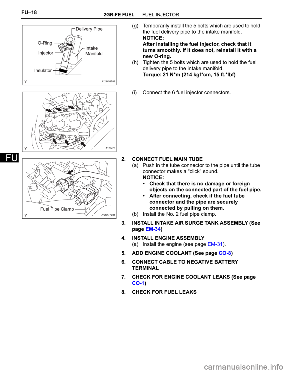
(g) Temporarily install the 5 bolts which are used to hold
the fuel delivery pipe to the intake manifold.
NOTICE:
After installing the fuel injector, check that it
turns smoothly. If it does not, reinstall it with a
new O-ring.
(h) Tighten the 5 bolts which are used to hold the fuel
delivery pipe to the intake manifold.
Torque: 21 N*m (214 kgf*cm, 15 ft.*lbf)
(i) Connect the 6 fuel injector connectors.
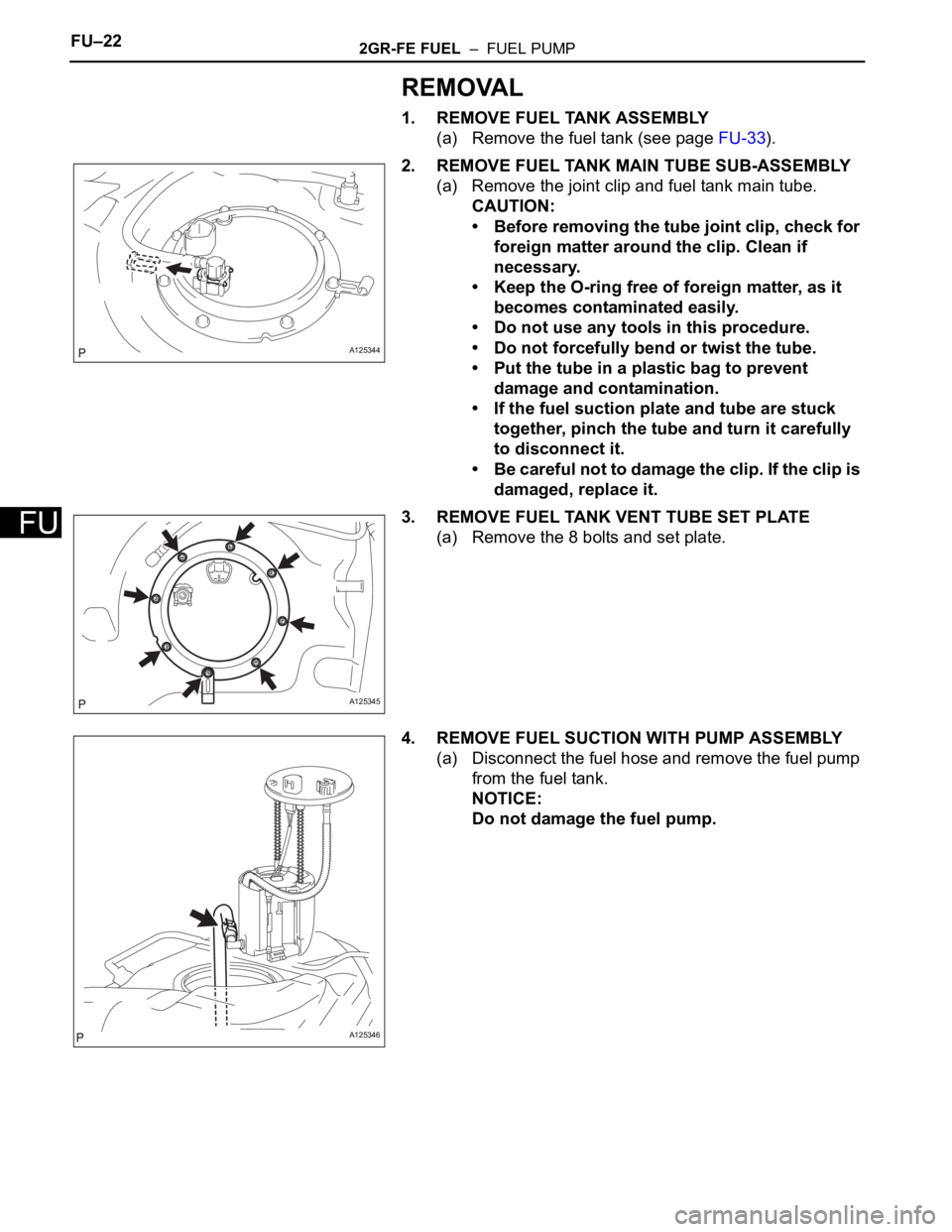
2. CONNECT FUEL MAIN TUBE
(a) Push in the tube connector to the pipe until the tube
connector makes a "click" sound.
NOTICE:
• Check that there is no damage or foreign
objects on the connected part of the fuel pipe.
• After connecting, check if the fuel tube
connector and the pipe are securely
connected by pulling on them.
(b) Install the No. 2 fuel pipe clamp.
3. INSTALL INTAKE AIR SURGE TANK ASSEMBLY (See
page EM-34)
4. INSTALL ENGINE ASSEMBLY
(a) Install the engine (see page EM-31).
5. ADD ENGINE COOLANT (See page CO-8)
6. CONNECT CABLE TO NEGATIVE BATTERY
TERMINAL
7. CHECK FOR ENGINE COOLANT LEAKS (See page
CO-1)
8. CHECK FOR FUEL LEAKS
A129458E02
A129470
A129477E01
Page 809 of 2000
FU–202GR-FE FUEL – FUEL PRESSURE PULSATION DAMPER
FU
INSTALLATION
1. INSTALL FUEL PRESSURE PULSATION DAMPER
(a) Apply a light coat of spindle oil or gasoline to a new
O-ring, and install it to the pulsation damper.
(b) Install the pulsation damper to the fuel delivery pipe.
(c) Install the clip.
2. INSTALL INTAKE AIR SURGE TANK ASSEMBLY (See
page EM-34)
3. INSTALL ENGINE ASSEMBLY
(a) Install the engine (see page EM-31).
4. CONNECT CABLE TO NEGATIVE BATTERY
TERMINAL
Page 810 of 2000

FU–222GR-FE FUEL – FUEL PUMP
FU
REMOVAL
1. REMOVE FUEL TANK ASSEMBLY
(a) Remove the fuel tank (see page FU-33).
2. REMOVE FUEL TANK MAIN TUBE SUB-ASSEMBLY
(a) Remove the joint clip and fuel tank main tube.
CAUTION:
• Before removing the tube joint clip, check for
foreign matter around the clip. Clean if
necessary.
• Keep the O-ring free of foreign matter, as it
becomes contaminated easily.
• Do not use any tools in this procedure.
• Do not forcefully bend or twist the tube.
• Put the tube in a plastic bag to prevent
damage and contamination.
• If the fuel suction plate and tube are stuck
together, pinch the tube and turn it carefully
to disconnect it.
• Be careful not to damage the clip. If the clip is
damaged, replace it.
3. REMOVE FUEL TANK VENT TUBE SET PLATE
(a) Remove the 8 bolts and set plate.
4. REMOVE FUEL SUCTION WITH PUMP ASSEMBLY
(a) Disconnect the fuel hose and remove the fuel pump
from the fuel tank.
NOTICE:
Do not damage the fuel pump.
A125344
A125345
A125346
Page 811 of 2000
2GR-FE FUEL – FUEL PUMPFU–23
FU
(b) Remove the gasket from the fuel pump.
5. REMOVE FUEL SUB-TANK ASSEMBLY
(a) Disconnect the wire harness.
(b) Using needle nose pliers, remove the E-ring.
HINT:
Slightly lower the sub-tank to remove the E-ring.
(c) Remove the 2 springs from the 2 shafts.
(d) Detach the 2 claws and remove the sub-tank.
A125347E01
A125348
A125349E01
A125350
A126125
Page 812 of 2000
FU–242GR-FE FUEL – FUEL PUMP
FU
(e) Detach the claw of the jet pump nozzle and remove
the jet pump nozzle.
(f) Using a screwdriver, remove the jet pump.
HINT:
Tape the screwdriver tip before use.
(g) Remove the O-ring from the jet pump.
6. REMOVE BRACKET
(a) Using a screwdriver, detach the 2 claws and remove
the bracket.
HINT:
Tape the screwdriver tip before use.
7. REMOVE FUEL PUMP ASSEMBLY
(a) Detach the 5 claws on the filter and remove the fuel
pump from the fuel filter.
HINT:
When removing the claw, do not disconnect the fuel
main tube.
A126798E01
A110138E01
A126126
A126129E01
Page 813 of 2000
2GR-FE FUEL – FUEL PUMPFU–25
FU
(b) Disconnect the fuel pump connector.
(c) Remove the O-ring from the fuel filter.
INSPECTION
1. INSPECT FUEL PUMP
(a) Check the fuel pump resistance.
(1) Measure the resistance between terminals 1
and 2.
Standard resistance:
0.2 to 3.0
at 20C (68F)
If the result is not as specified, replace the fuel
pump.
(b) Check fuel pump operation.
(1) Apply battery voltage to terminals 1 and 2.
Check that the pump operates.
NOTICE:
• These tests must be completed within 10
seconds to prevent the coil from burning
out.
• Keep the fuel pump as far away from the
battery as possible.
• Always turn the voltage on and off on the
battery side, not the fuel pump side.
A126130
A126641E03
A126943
Page 814 of 2000
FU–262GR-FE FUEL – FUEL PUMP
FU
If the pump does not operate, replace the fuel
pump.
INSTALLATION
1. INSTALL FUEL PUMP ASSEMBLY
(a) Connect the pump harness connector.
(b) Apply gasoline to a new O-ring and install the O-ring
to the fuel filter.
(c) Attach the 5 claws to the claw holes and install the
fuel pump.
2. INSTALL BRACKET
(a) Attach the 2 claws to the claw holes and install the
bracket.
A126130
A131633E01
A126126
Page 815 of 2000
2GR-FE FUEL – FUEL PUMPFU–27
FU
3. INSTALL FUEL SUB-TANK ASSEMBLY
(a) Apply gasoline to a new O-ring and install it to the
jet pump.
(b) Install the jet pump while aligning it with the
installation position of the sub-tank.
(c) Install the jet pump nozzle.
(d) Attach the 2 claws to the claw holes and install the
fuel sub-tank.
(e) Connect the wire harness.
(f) Install the springs to the fuel suction plate shafts and
install them to the sub-tank.
A110138E02
A130453
A126125
A125348
A125350