Page 760 of 2000

2GR-FE ENGINE MECHANICAL – ENGINE UNITEM–123
EM
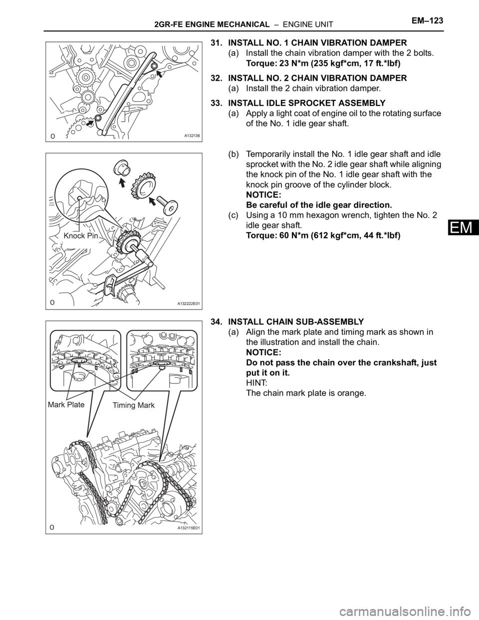
31. INSTALL NO. 1 CHAIN VIBRATION DAMPER
(a) Install the chain vibration damper with the 2 bolts.
Torque: 23 N*m (235 kgf*cm, 17 ft.*lbf)
32. INSTALL NO. 2 CHAIN VIBRATION DAMPER
(a) Install the 2 chain vibration damper.
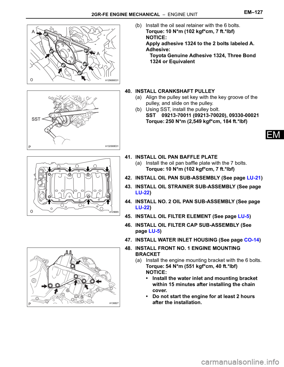
33. INSTALL IDLE SPROCKET ASSEMBLY
(a) Apply a light coat of engine oil to the rotating surface
of the No. 1 idle gear shaft.
(b) Temporarily install the No. 1 idle gear shaft and idle
sprocket with the No. 2 idle gear shaft while aligning
the knock pin of the No. 1 idle gear shaft with the
knock pin groove of the cylinder block.
NOTICE:
Be careful of the idle gear direction.
(c) Using a 10 mm hexagon wrench, tighten the No. 2
idle gear shaft.
Torque: 60 N*m (612 kgf*cm, 44 ft.*lbf)
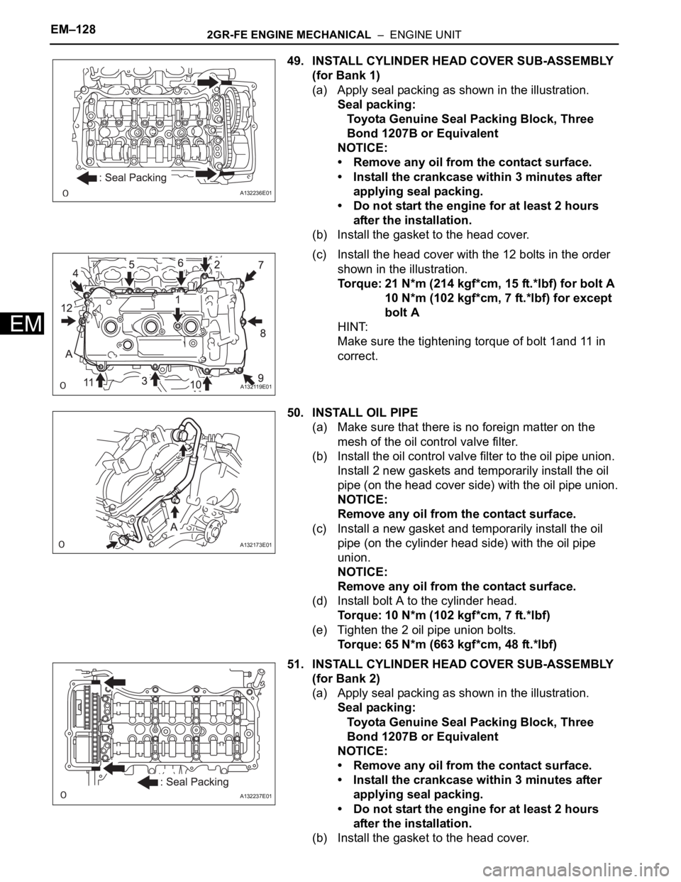
34. INSTALL CHAIN SUB-ASSEMBLY
(a) Align the mark plate and timing mark as shown in
the illustration and install the chain.
NOTICE:
Do not pass the chain over the crankshaft, just
put it on it.
HINT:
The chain mark plate is orange.
A132136
A132222E01
A132115E01
Page 761 of 2000
EM–1242GR-FE ENGINE MECHANICAL – ENGINE UNIT
EM
(b) Turn the camshaft timing gear on the bank 1
counterclockwise to tighten the chain between the
banks.
NOTICE:
If reusing the idle sprocket, align one of the idle
sprocket's chain plate marks with one of the
chain's chain plates when installing the idle
sprocket.
(c) Align the mark plate and timing mark as shown in
the illustration and install the chain onto the
crankshaft timing gear.
HINT:
The chain mark plate is yellow.
(d) Temporarily tighten the pulley set bolt.
(e) Turn the crankshaft clockwise to set it to the bank 1
block bore center line (TDC / compression).
35. INSTALL CHAIN TENSIONER SLIPPER
(a) Install the chain tensioner slipper.
A122184E05
A132116E01
A132112E01
Page 762 of 2000
2GR-FE ENGINE MECHANICAL – ENGINE UNITEM–125
EM
36. INSTALL NO. 1 CHAIN TENSIONER ASSEMBLY
(a) Move the stopper plate upward to release the lock,
and push the plunger deep into the tensioner.
(b) Move the stopper plate downward to set the lock,
and insert a hexagon wrench into the hole of the
stopper plate.
(c) Install the chain tensioner with the 2 bolts.
Torque: 10 N*m (102 kgf*cm, 7 ft.*lbf)
A131974E01
A132020
Page 763 of 2000
EM–1262GR-FE ENGINE MECHANICAL – ENGINE UNIT
EM
(d) Remove the lock pin of the chain tensioner. Check
that each timing mark is aligned with the crankshaft
at the TDC / compression.
(e) Remove the pulley set bolt.
37. INSTALL TIMING CHAIN COVER SUB-ASSEMBLY (w/
Oil Pump) (See page LU-17)
38. INSTALL WATER PUMP ASSEMBLY (See page CO-
13)
39. INSTALL ENGINE REAR OIL SEAL RETAINER
(a) Apply seal packing in a continuous line as shown in
the illustration.
Seal packing:
Toyota Genuine Seal Packing Block, Three
Bond 1207B or Equivalent
Standard seal diameter:
2.0 to 3.0 mm (0.079 to 0.118 in.)
NOTICE:
• Remove any oil from the contact surface.
• Install the crankcase within 3 minutes after
applying seal packing.
• Do not start the engine for at least 2 hours
after the installation.
A132117E01
A131897E03
Page 764 of 2000

2GR-FE ENGINE MECHANICAL – ENGINE UNITEM–127
EM
(b) Install the oil seal retainer with the 6 bolts.
Torque: 10 N*m (102 kgf*cm, 7 ft.*lbf)
NOTICE:
Apply adhesive 1324 to the 2 bolts labeled A.
Adhesive:
Toyota Genuine Adhesive 1324, Three Bond
1324 or Equivalent
40. INSTALL CRANKSHAFT PULLEY
(a) Align the pulley set key with the key groove of the
pulley, and slide on the pulley.
(b) Using SST, install the pulley bolt.
SST 09213-70011 (09213-70020), 09330-00021
Torque: 250 N*m (2,549 kgf*cm, 184 ft.*lbf)
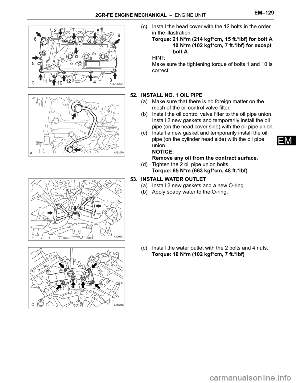
41. INSTALL OIL PAN BAFFLE PLATE
(a) Install the oil pan baffle plate with the 7 bolts.
Torque: 10 N*m (102 kgf*cm, 7 ft.*lbf)
42. INSTALL OIL PAN SUB-ASSEMBLY (See page LU-21)
43. INSTALL OIL STRAINER SUB-ASSEMBLY (See page
LU-22)
44. INSTALL NO. 2 OIL PAN SUB-ASSEMBLY (See page
LU-22)
45. INSTALL OIL FILTER ELEMENT (See page LU-5)
46. INSTALL OIL FILTER CAP SUB-ASSEMBLY (See
page LU-5)
47. INSTALL WATER INLET HOUSING (See page CO-14)
48. INSTALL FRONT NO. 1 ENGINE MOUNTING
BRACKET
(a) Install the engine mounting bracket with the 6 bolts.
Torque: 54 N*m (551 kgf*cm, 40 ft.*lbf)
NOTICE:
• Install the water inlet and mounting bracket
within 15 minutes after installing the chain
cover.
• Do not start the engine for at least 2 hours
after the installation.
A129686E01
A132068E01
A129685
A136827
Page 765 of 2000

EM–1282GR-FE ENGINE MECHANICAL – ENGINE UNIT
EM
49. INSTALL CYLINDER HEAD COVER SUB-ASSEMBLY
(for Bank 1)
(a) Apply seal packing as shown in the illustration.
Seal packing:
Toyota Genuine Seal Packing Block, Three
Bond 1207B or Equivalent
NOTICE:
• Remove any oil from the contact surface.
• Install the crankcase within 3 minutes after
applying seal packing.
• Do not start the engine for at least 2 hours
after the installation.
(b) Install the gasket to the head cover.
(c) Install the head cover with the 12 bolts in the order
shown in the illustration.
Torque: 21 N*m (214 kgf*cm, 15 ft.*lbf) for bolt A
10 N*m (102 kgf*cm, 7 ft.*lbf) for except
bolt A
HINT:
Make sure the tightening torque of bolt 1and 11 in
correct.
50. INSTALL OIL PIPE
(a) Make sure that there is no foreign matter on the
mesh of the oil control valve filter.
(b) Install the oil control valve filter to the oil pipe union.
Install 2 new gaskets and temporarily install the oil
pipe (on the head cover side) with the oil pipe union.
NOTICE:
Remove any oil from the contact surface.
(c) Install a new gasket and temporarily install the oil
pipe (on the cylinder head side) with the oil pipe
union.
NOTICE:
Remove any oil from the contact surface.
(d) Install bolt A to the cylinder head.
Torque: 10 N*m (102 kgf*cm, 7 ft.*lbf)
(e) Tighten the 2 oil pipe union bolts.
Torque: 65 N*m (663 kgf*cm, 48 ft.*lbf)
51. INSTALL CYLINDER HEAD COVER SUB-ASSEMBLY
(for Bank 2)
(a) Apply seal packing as shown in the illustration.
Seal packing:
Toyota Genuine Seal Packing Block, Three
Bond 1207B or Equivalent
NOTICE:
• Remove any oil from the contact surface.
• Install the crankcase within 3 minutes after
applying seal packing.
• Do not start the engine for at least 2 hours
after the installation.
(b) Install the gasket to the head cover.
A132236E01
A132119E01
A132173E01
A132237E01
Page 766 of 2000

2GR-FE ENGINE MECHANICAL – ENGINE UNITEM–129
EM
(c) Install the head cover with the 12 bolts in the order
in the illastration.
Torque: 21 N*m (214 kgf*cm, 15 ft.*lbf) for bolt A
10 N*m (102 kgf*cm, 7 ft.*lbf) for except
bolt A
HINT:
Make sure the tightening torque of bolts 1 and 10 is
correct.
52. INSTALL NO. 1 OIL PIPE
(a) Make sure that there is no foreign matter on the
mesh of the oil control valve filter.
(b) Install the oil control valve filter to the oil pipe union.
Install 2 new gaskets and temporarily install the oil
pipe (on the head cover side) with the oil pipe union.
(c) Install a new gasket and temporarily install the oil
pipe (on the cylinder head side) with the oil pipe
union.
NOTICE:
Remove any oil from the contract surface.
(d) Tighten the 2 oil pipe union bolts.
Torque: 65 N*m (663 kgf*cm, 48 ft.*lbf)
53. INSTALL WATER OUTLET
(a) Install 2 new gaskets and a new O-ring.
(b) Apply soapy water to the O-ring.
(c) Install the water outlet with the 2 bolts and 4 nuts.
Torque: 10 N*m (102 kgf*cm, 7 ft.*lbf)
A132120E01
A132070
A129677
A129676
Page 767 of 2000
EM–1302GR-FE ENGINE MECHANICAL – ENGINE UNIT
EM
54. INSTALL CAMSHAFT TIMING OIL CONTROL VALVE
ASSEMBLY
(a) Install the 4 camshaft timing oil control valves with
the 4 bolts.
Torque: 10 N*m (102 kgf*cm, 7 ft.*lbf)
55. INSTALL VVT SENSOR
(a) Install the 4 VVT sensors with the 4 bolts.
Torque: 10 N*m (102 kgf*cm, 7 ft.*lbf)
56. INSTALL SPARK PLUG
(a) Install the 6 spark plugs.
Torque: 18 N*m (184 kgf*cm, 13 ft.*lbf)
A131977E01
A131976E01