Page 415 of 2000

BRAKE – BRAKE SYSTEMBR–3
BR
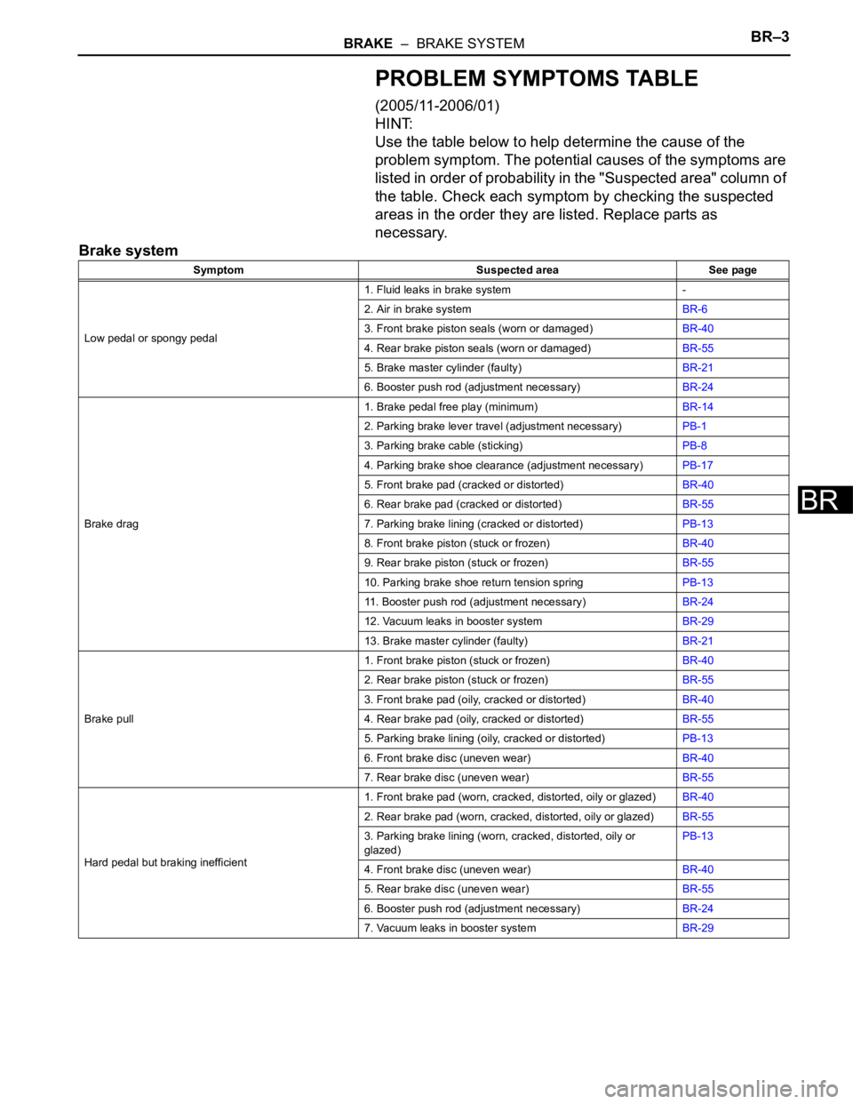
PROBLEM SYMPTOMS TABLE
(2005/11-2006/01)
HINT:
Use the table below to help determine the cause of the
problem symptom. The potential causes of the symptoms are
listed in order of probability in the "Suspected area" column of
the table. Check each symptom by checking the suspected
areas in the order they are listed. Replace parts as
necessary.
Brake system
Symptom Suspected area See page
Low pedal or spongy pedal1. Fluid leaks in brake system -
2. Air in brake systemBR-6
3. Front brake piston seals (worn or damaged)BR-40
4. Rear brake piston seals (worn or damaged)BR-55
5. Brake master cylinder (faulty)BR-21
6. Booster push rod (adjustment necessary)BR-24
Brake drag1. Brake pedal free play (minimum)BR-14
2. Parking brake lever travel (adjustment necessary)PB-1
3. Parking brake cable (sticking)PB-8
4. Parking brake shoe clearance (adjustment necessary)PB-17
5. Front brake pad (cracked or distorted)BR-40
6. Rear brake pad (cracked or distorted)BR-55
7. Parking brake lining (cracked or distorted)PB-13
8. Front brake piston (stuck or frozen)BR-40
9. Rear brake piston (stuck or frozen)BR-55
10. Parking brake shoe return tension springPB-13
11. Booster push rod (adjustment necessary)BR-24
12. Vacuum leaks in booster systemBR-29
13. Brake master cylinder (faulty)BR-21
Brake pull1. Front brake piston (stuck or frozen)BR-40
2. Rear brake piston (stuck or frozen)BR-55
3. Front brake pad (oily, cracked or distorted)BR-40
4. Rear brake pad (oily, cracked or distorted)BR-55
5. Parking brake lining (oily, cracked or distorted)PB-13
6. Front brake disc (uneven wear)BR-40
7. Rear brake disc (uneven wear)BR-55
Hard pedal but braking inefficient1. Front brake pad (worn, cracked, distorted, oily or glazed)BR-40
2. Rear brake pad (worn, cracked, distorted, oily or glazed)BR-55
3. Parking brake lining (worn, cracked, distorted, oily or
glazed)PB-13
4. Front brake disc (uneven wear)BR-40
5. Rear brake disc (uneven wear)BR-55
6. Booster push rod (adjustment necessary)BR-24
7. Vacuum leaks in booster systemBR-29
Page 416 of 2000
BR–4BRAKE – BRAKE SYSTEM
BR
Noise from brakes1. Front brake pad (cracked, distorted, dirty or glazed)BR-40
2. Rear brake pad (cracked, distorted, dirty or glazed)BR-55
3. Front disc brake pad support plate (loose)BR-40
4. Rear disc brake pad support plate (loose)BR-55
5. Front disc brake cylinder slide pin (worn)BR-40
6. Rear disc brake cylinder slide pin (worn)BR-55
7. Front brake installation bolt (loose)BR-45
8. Rear brake installation bolt (loose)BR-60
9. Front brake disc (scored)BR-40
10. Rear brake disc (scored)BR-55
11. Parking brake shoe return tension spring (faulty)PB-13
12. Front brake anti-squeal shim (damaged)BR-40
13. Rear brake anti-squeal shim (damaged)BR-55
14. Parking brake shoe hold-down spring (damaged)PB-13 Symptom Suspected area See page
Page 417 of 2000

PARKING BRAKE – PARKING BRAKE LEVERPB–5
PB
REMOVAL
1. DISCONNECT CABLE FROM NEGATIVE BATTERY
TERMINAL
CAUTION:
Wait at least 90 seconds after disconnecting the
cable from the negative (-) battery terminal to
prevent airbag and seat belt pretensioner activation.
2. REMOVE REAR CONSOLE BOX SUB-ASSEMBLY
(a) Remove the rear console box (see page IP-16).
HINT:
Refer to the procedures from the removal of the No.
1 console upper panel garnish up until the removal
of the rear console box sub-assembly.
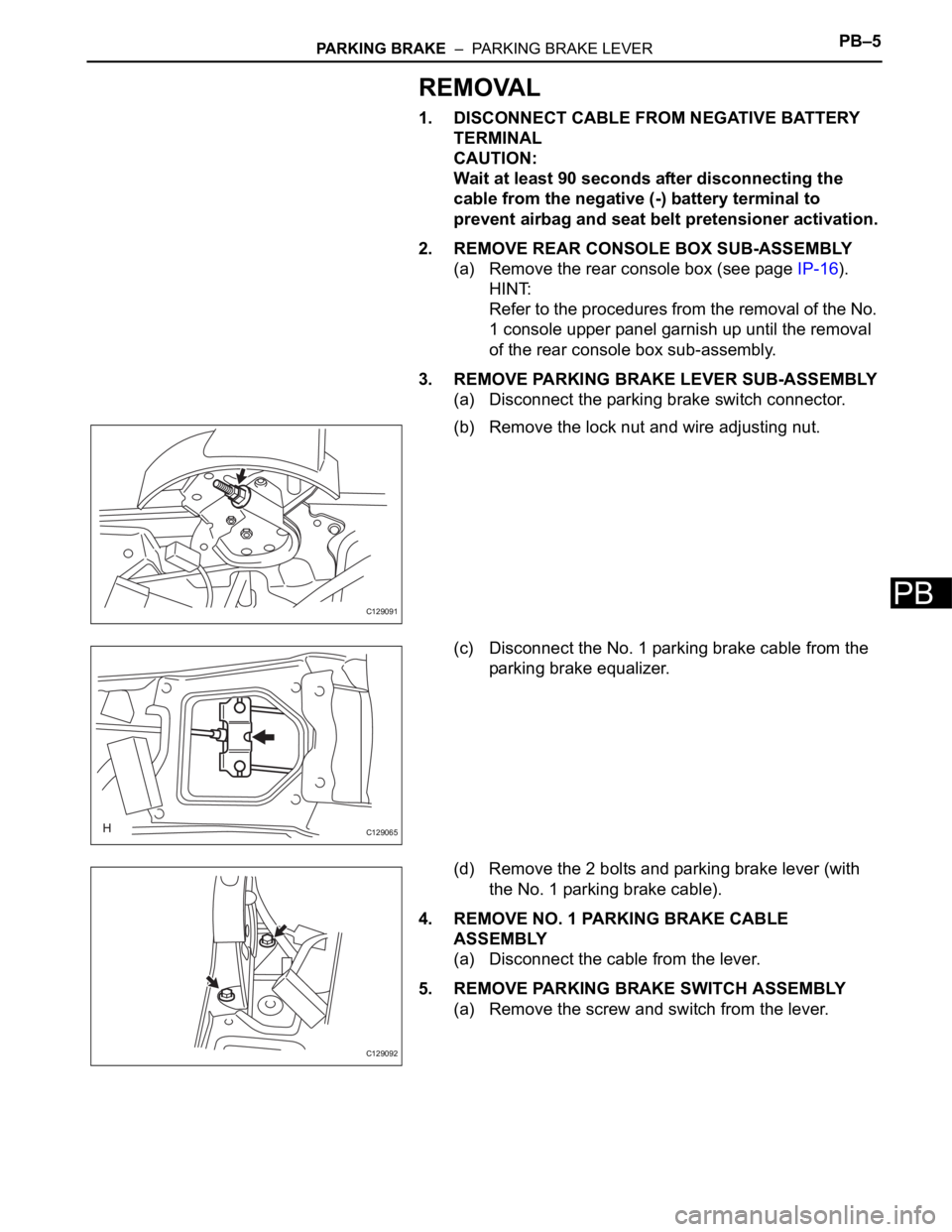
3. REMOVE PARKING BRAKE LEVER SUB-ASSEMBLY
(a) Disconnect the parking brake switch connector.
(b) Remove the lock nut and wire adjusting nut.
(c) Disconnect the No. 1 parking brake cable from the
parking brake equalizer.
(d) Remove the 2 bolts and parking brake lever (with
the No. 1 parking brake cable).
4. REMOVE NO. 1 PARKING BRAKE CABLE
ASSEMBLY
(a) Disconnect the cable from the lever.
5. REMOVE PARKING BRAKE SWITCH ASSEMBLY
(a) Remove the screw and switch from the lever.
C129091
C129065
C129092
Page 418 of 2000

PB–6PARKING BRAKE – PARKING BRAKE LEVER
PB
INSTALLATION
1. INSTALL PARKING BRAKE SWITCH ASSEMBLY
(a) Install the parking brake switch with the screw.
Torque: 0.88 N*m (9.0 kgf*cm, 7.8 in.*lbf)
2. INSTALL NO. 1 PARKING BRAKE CABLE ASSEMBLY
(a) Connect the cable to the lever.
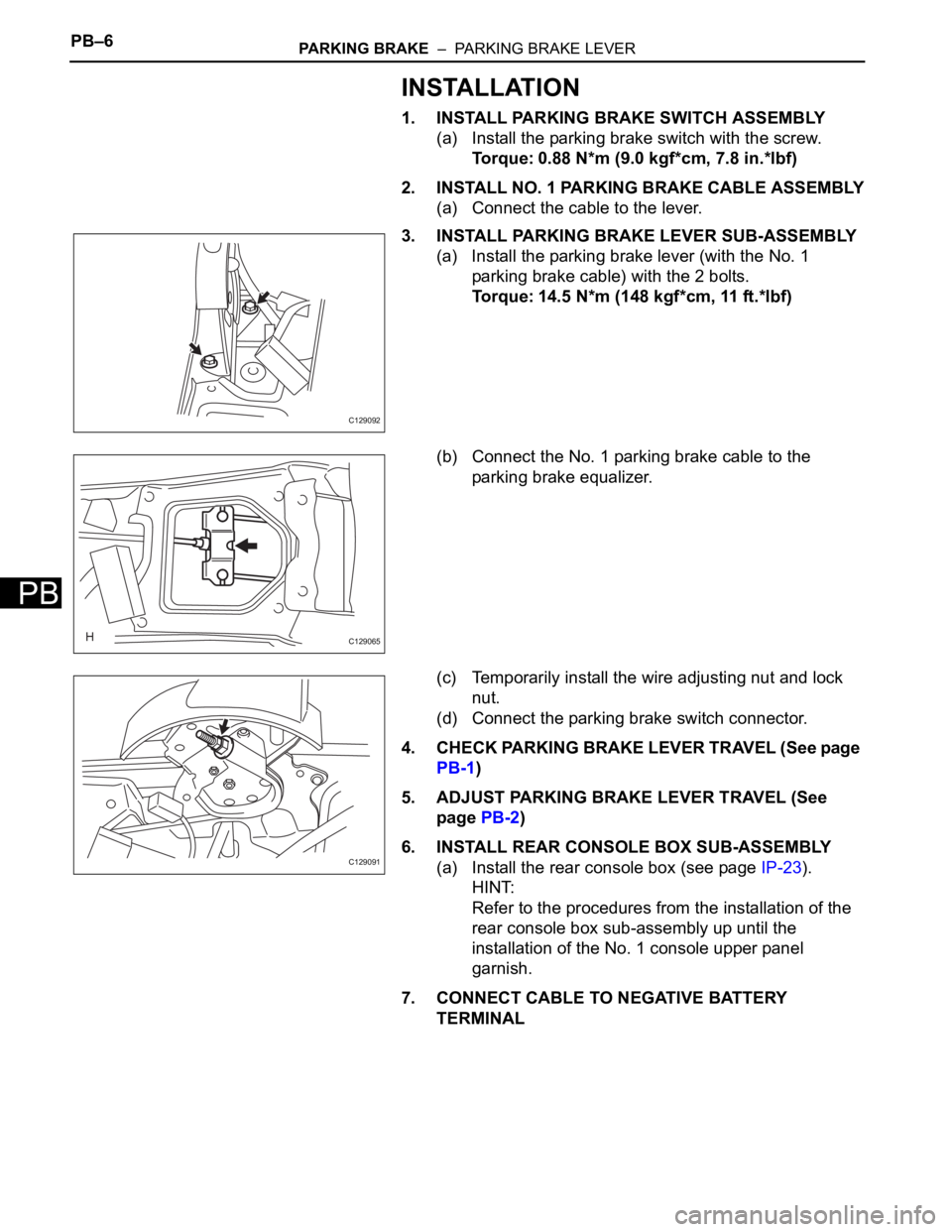
3. INSTALL PARKING BRAKE LEVER SUB-ASSEMBLY
(a) Install the parking brake lever (with the No. 1
parking brake cable) with the 2 bolts.
Torque: 14.5 N*m (148 kgf*cm, 11 ft.*lbf)
(b) Connect the No. 1 parking brake cable to the
parking brake equalizer.
(c) Temporarily install the wire adjusting nut and lock
nut.
(d) Connect the parking brake switch connector.
4. CHECK PARKING BRAKE LEVER TRAVEL (See page
PB-1)
5. ADJUST PARKING BRAKE LEVER TRAVEL (See
page PB-2)
6. INSTALL REAR CONSOLE BOX SUB-ASSEMBLY
(a) Install the rear console box (see page IP-23).
HINT:
Refer to the procedures from the installation of the
rear console box sub-assembly up until the
installation of the No. 1 console upper panel
garnish.
7. CONNECT CABLE TO NEGATIVE BATTERY
TERMINAL
C129092
C129065
C129091
Page 792 of 2000
FU–402AZ-FE FUEL – FUEL TANK
FU
REMOVAL
1. DISCHARGE FUEL SYSTEM PRESSURE (See page
FU-9)
2. DISCONNECT CABLE FROM NEGATIVE BATTERY
TERMINAL
CAUTION:
Wait at least 90 seconds after disconnecting the
cable from the negative (-) battery terminal to
prevent airbag and seat belt pretensioner activation.
3. REMOVE FUEL TANK CAP
4. REMOVE FRONT FLOOR COVER
(a) Remove the nut, bolt, 3 clips and floor cover.
5. REMOVE NO. 1 FLOOR UNDER COVER
(a) Remove the 2 nuts, clip and floor under cover.
6. DISCONNECT NO. 2 PARKING BRAKE CABLE
ASSEMBLY
(a) Remove the 2 bolts and disconnect the parking
brake cable.
A124659
A131635
Page 800 of 2000
FU–482AZ-FE FUEL – FUEL TANK
FU
8. INSTALL NO. 2 PARKING BRAKE CABLE ASSEMBLY
(a) Install the parking brake cable with the 2 bolts.
9. INSTALL FUEL TANK CAP
10. CONNECT CABLE TO NEGATIVE BATTERY
TERMINAL
11. CHECK FOR FUEL LEAKS (See page FU-14)
A124660
Page 818 of 2000
FU–342GR-FE FUEL – FUEL TANK
FU
REMOVAL
1. DISCHARGE FUEL SYSTEM PRESSURE (See page
FU-13)
2. DISCONNECT CABLE FROM NEGATIVE BATTERY
TERMINAL
CAUTION:
Wait at least 90 seconds after disconnecting the
cable from the negative (-) battery terminal to
prevent airbag and seat belt pretensioner activation.
3. REMOVE FUEL TANK CAP
4. REMOVE FRONT FLOOR COVER
(a) Remove the nut, bolt, 3 clips and floor cover.
5. REMOVE NO. 1 FLOOR UNDER COVER
(a) Remove the 2 nuts, clip and floor under cover.
6. DISCONNECT NO. 2 PARKING BRAKE CABLE
ASSEMBLY
(a) Remove the 2 bolts and disconnect the parking
brake cable.
A124659
A131635
Page 826 of 2000
FU–422GR-FE FUEL – FUEL TANK
FU
8. INSTALL NO. 2 PARKING BRAKE CABLE ASSEMBLY
(a) Install the parking brake cable with the 2 bolts.
9. INSTALL FUEL TANK CAP
10. CONNECT CABLE TO NEGATIVE BATTERY
TERMINAL
11. CHECK FOR FUEL LEAKS
A124660