Page 1862 of 2000
LIGHTING – LIGHTING SYSTEMLI–31
LI
Main body ECU
OK:
Headlight comes on
OK
NG
(a) Remove the HEAD LL fuse and HEAD RL fuse from the
engine room No. 2 relay block.
(b) Measure the resistance of the fuses.
Standard resistance:
Below 1
NG
OK
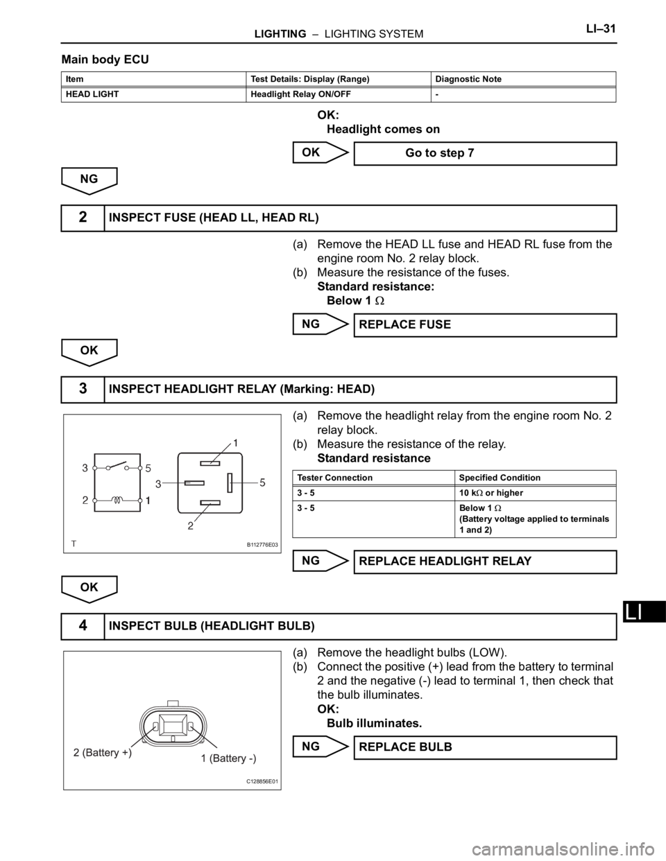
(a) Remove the headlight relay from the engine room No. 2
relay block.
(b) Measure the resistance of the relay.
Standard resistance
NG
OK
(a) Remove the headlight bulbs (LOW).
(b) Connect the positive (+) lead from the battery to terminal
2 and the negative (-) lead to terminal 1, then check that
the bulb illuminates.
OK:
Bulb illuminates.
NG
Item Test Details: Display (Range) Diagnostic Note
HEAD LIGHT Headlight Relay ON/OFF -
Go to step 7
2INSPECT FUSE (HEAD LL, HEAD RL)
REPLACE FUSE
3INSPECT HEADLIGHT RELAY (Marking: HEAD)
B112776E03
Tester Connection Specified Condition
3 - 5 10 k
or higher
3 - 5 Below 1
(Battery voltage applied to terminals
1 and 2)
REPLACE HEADLIGHT RELAY
4INSPECT BULB (HEADLIGHT BULB)
C128856E01
REPLACE BULB
Page 1863 of 2000
LI–32LIGHTING – LIGHTING SYSTEM
LI
OK
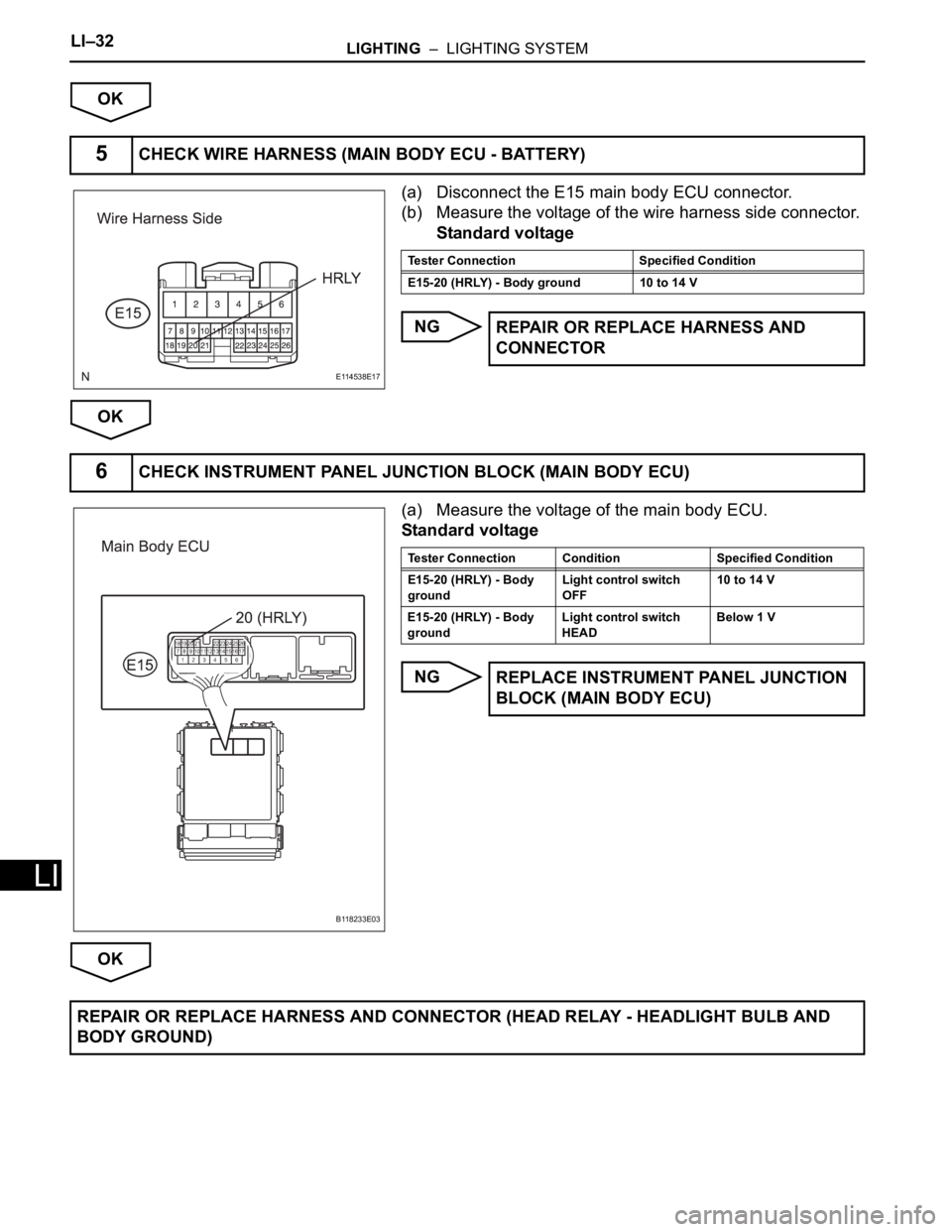
(a) Disconnect the E15 main body ECU connector.
(b) Measure the voltage of the wire harness side connector.
Standard voltage
NG
OK
(a) Measure the voltage of the main body ECU.
Standard voltage
NG
OK
5CHECK WIRE HARNESS (MAIN BODY ECU - BATTERY)
E114538E17
Tester Connection Specified Condition
E15-20 (HRLY) - Body ground 10 to 14 V
REPAIR OR REPLACE HARNESS AND
CONNECTOR
6CHECK INSTRUMENT PANEL JUNCTION BLOCK (MAIN BODY ECU)
B118233E03
Tester Connection Condition Specified Condition
E15-20 (HRLY) - Body
groundLight control switch
OFF10 to 14 V
E15-20 (HRLY) - Body
groundLight control switch
HEADBelow 1 V
REPLACE INSTRUMENT PANEL JUNCTION
BLOCK (MAIN BODY ECU)
REPAIR OR REPLACE HARNESS AND CONNECTOR (HEAD RELAY - HEADLIGHT BULB AND
BODY GROUND)
Page 1868 of 2000
LIGHTING – LIGHTING SYSTEMLI–37
LI
(a) Remove the headlight bulb (high).
(b) Connect the positive (+) lead from the battery to terminal
2 and the negative (-) lead to terminal 1, then check that
the bulb illuminates.
NG
OK
(a) Remove the No. 2 daytime running light relay from the
engine room No. 2 relay block.
(b) Measure the voltage of the relay block.
Standard voltage
NG
OK
3INSPECT HEADLIGHT BULB (HIGH)
C128857E01
REPLACE HEADLIGHT BULB (HIGH)
4CHECK WIRE HARNESS (BATTERY - NO. 2 DAYTIME RUNNING LIGHT RELAY)
B118199E04
Tester Connection Specified Condition
Relay block daytime running light
No. 2 relay terminal 5 - Body ground10 to 14 V
REPAIR OR REPLACE HARNESS AND
CONNECTOR
Page 1869 of 2000

LI–38LIGHTING – LIGHTING SYSTEM
LI
(a) Remove the No. 2 daytime running light relay from the
engine room No. 2 relay block.
(b) Disconnect the A14 and A22 headlight (HIGH)
connectors.
(c) Measure the resistance of the wire harness side
connectors and relay block.
Standard resistance
NG
OK
(a) Disconnect the E16 main body ECU connector.
(b) Measure the voltage of the wire harness side connector.
Standard voltage
NG
OK
5CHECK WIRE HARNESS (NO. 2 DAYTIME RUNNING LIGHT RELAY - HEADLIGHT BULB
AND BODY GROUND)
B118200E09
Tester Connection Specified Condition
Relay block daytime running light
No. 2 relay terminal 3 - A14-2Below 1
A14-2 - Body ground 10 k or higher
A14-1 - A22-1 Below 1
A14-1 - Body ground 10 k or higher
A22-2 - Body ground Below 1
REPAIR OR REPLACE HARNESS AND
CONNECTOR
6CHECK WIRE HARNESS (MAIN BODY ECU - BATTERY)
B118235E01
Tester Connection Specified Condition
E16-3 (DIM) - Body ground 10 to 14 V
REPAIR OR REPLACE HARNESS AND
CONNECTOR
REPLACE INSTRUMENT PANEL JUNCTION BLOCK (MAIN BODY ECU)
Page 1873 of 2000
LI–42LIGHTING – LIGHTING SYSTEM
LI
(a) Remove the headlight bulb (HIGH).
(b) Connect the positive (+) lead from the battery to terminal
2 and the negative (-) lead to terminal 1, then check that
the bulb illuminates.
NG
OK
(a) Disconnect the E16 main body ECU connector.
(b) Measure the voltage of the wire harness side connector.
Standard voltage
NG
OK
(a) Remove the headlight relay from the engine room No. 2
relay block.
(b) Disconnect the E15 main body ECU connector.
(c) Measure the voltage of the wire harness side connector.
Standard voltage
NG
OK
5INSPECT HEADLIGHT BULB (HIGH)
C128857E01
REPLACE HEADLIGHT BULB (HIGH)
6CHECK WIRE HARNESS (MAIN BODY ECU - BATTERY)
B118235E01
Tester Connection Specified Condition
E16-3 (DIM) - Body ground 10 to 14 V
REPAIR OR REPLACE HARNESS AND
CONNECTOR
7CHECK WIRE HARNESS (MAIN BODY ECU)
E114538E17
Tester Connection Specified Condition
E15-20 (HRLY) - Body ground 10 to 14 V
REPAIR OR REPLACE HARNESS AND
CONNECTOR
Page 1875 of 2000

LI–44LIGHTING – LIGHTING SYSTEM
LI
(a) Remove the No. 2 daytime running light relay from the
engine room No. 2 relay block.
(b) Remove the A14 and A22 headlight bulb connectors.
(c) Measure the voltage and resistance of the relay block.
Standard voltage
Standard resistance
NG
OK
9CHECK WIRE HARNESS (BATTERY - NO. 2 DAYTIME RUNNING LIGHT RELAY, BULB
AND BODY GROUND)
B118200E10
Tester Connection Specified Condition
Relay block No. 2 daytime running
light relay terminal 5 - Body ground10 to 14 V
Tester Connection Condition Specified Condition
Relay block No. 2
daytime running light
relay terminal 3 - A14-2Always Below 1
Relay block No. 2
daytime running light
relay terminal 3 - Body
groundAlways 10 k or higher
A14-1 - A22-1 Always Below 1
A14-1 or A22-1 - Body
groundAlways 10 k or higher
A22-2 - Body ground Always Below 1
Relay block No. 2
daytime running light
relay terminal 3 - A22-2Light control switch ON
(HEAD)
Dimmer switch position
LOWBelow 1
Relay block No. 2
daytime running light
relay terminal 3 - Body
groundLight control switch ON
(HEAD)
Dimmer switch position
LOW10 k or higher
A22-1 - Body ground Light control switch ON
(HEAD)
Dimmer switch position
LOWBelow 1
REPAIR OR REPLACE HARNESS AND
CONNECTOR
REPLACE INSTRUMENT PANEL JUNCTION BLOCK (MAIN BODY ECU)
Page 1879 of 2000
LI–48LIGHTING – LIGHTING SYSTEM
LI
(b) Turn the ignition switch to the ON position and press the
intelligent tester main switch ON.
(c) Select the item below in the ACTIVE TEST and then
check the relay operation.
Main body ECU
OK:
Front fog light comes on.
OK
NG
(a) Check that the taillight comes on when the light control
switch is on (TAIL).
OK:
Taillight comes on.
NG
OK
(a) Remove the FR FOG fuse from the instrument panel
junction block.
(b) Measure the resistance of the fuses.
Standard resistance:
Below 1
NG
OK
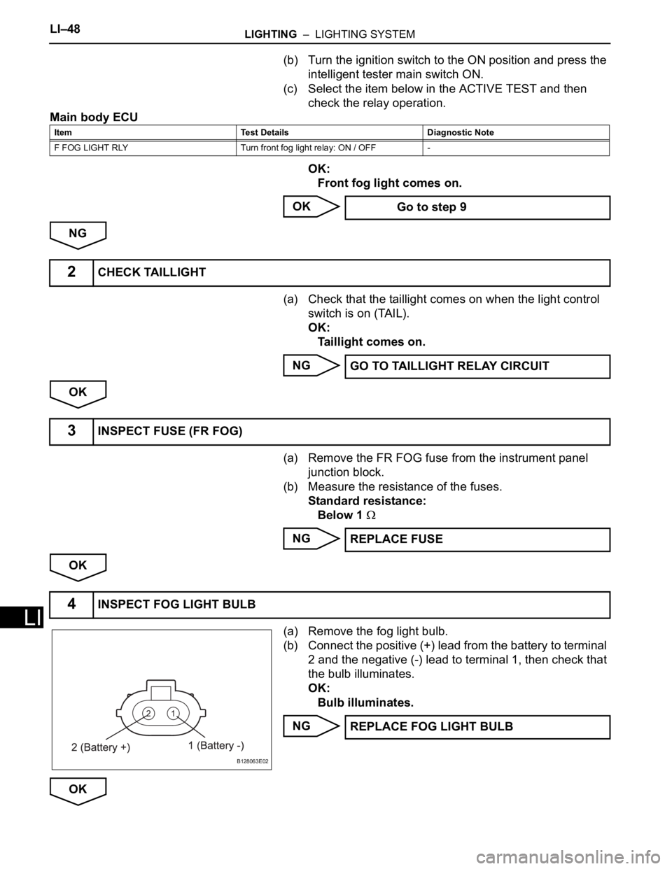
(a) Remove the fog light bulb.
(b) Connect the positive (+) lead from the battery to terminal
2 and the negative (-) lead to terminal 1, then check that
the bulb illuminates.
OK:
Bulb illuminates.
NG
OK
Item Test Details Diagnostic Note
F FOG LIGHT RLY Turn front fog light relay: ON / OFF -
Go to step 9
2CHECK TAILLIGHT
GO TO TAILLIGHT RELAY CIRCUIT
3INSPECT FUSE (FR FOG)
REPLACE FUSE
4INSPECT FOG LIGHT BULB
B128063E02
REPLACE FOG LIGHT BULB
Page 1883 of 2000
LIGHTING – VANITY LIGHTLI–129
LI
(b) Inspect vanity light switch.
Standard resistance
If the result is not as specified, replace the visor
assembly.
INSTALLATION
1. INSTALL VANITY LIGHT BULB
(a) Install the light bulb to the vanity light.
2. INSTALL VANITY LIGHT ASSEMBLY
(a) Attach the 2 claws and install the vanity light lens to
the vanity light.
(b) Install the vanity light.
3. CONNECT CABLE TO NEGATIVE BATTERY
TERMINAL
Tester Connection Condition Specified Condition
1 (L) - 2 (B) Visor raise 10 k
or higher
Visor lower and mirror
cover openBelow 1
Visor lower and mirror
cover close10 k or higher
B131426
B131425
B131424