2006 TOYOTA RAV4 gas type
[x] Cancel search: gas typePage 2 of 2000

ENGINE - 2AZ-FE ENGINE
DR011EG20
Cylinder Head Cover
Cylinder Head Cover Gasket
02AEG02Y 02AEG01Y
Cylinder
Bore Side
FrontOuter
Side
Shim A
A
A - A Cross SectionEG-5
ENGINE PROPER
1. Cylinder Head Cover
A lightweight magnesium alloy die-cast
cylinder head cover is used.
Acrylic rubber, which excels in heat resistance
and reliability, is used for the cylinder head
cover gasket.
2. Cylinder Head Gasket
A steel-laminate type cylinder head gasket is used. A shim has been added around the cylinder bore to
increase the sealing surface, thus improving the sealing performance and durability.
Page 17 of 2000

ENGINE - 2AZ-FE ENGINE
01NEG37Y
Mesh Type Gasket
01NEG38Y
TWC EG-20
4. Intake Manifold
The intake manifold has been made of plastic to reduce the weight and the amount of heat transferred from
the cylinder head. As a result, it has become possible to reduce the intake air temperature and improve the
intake volumetric efficiency.
A mesh type gasket is used, in order to reduce the intake noise.
5. Exhaust Manifold
A stainless steel exhaust manifold is used for improving the warm-up of TWC (Three-Way Catalytic
converter) and for weight reduction.
Page 27 of 2000

ENGINE - 2AZ-FE ENGINE EG-30
ENGINE CONTROL SYSTEM
1. General
The engine control system for the 2AZ-FE engine has the following systems.
System
Outline
SFI
Sequential Multiport
Fuel InjectionAn L-type SFI system directly detects the intake air volume with a hot-wire
type mass air flow meter.
The fuel injection system is a sequential multiport fuel injection system.
ESA
Electronic Spark
AdvanceIgnition timing is determined by the ECM based on signals from various sensors.
The ECM corrects ignition timing in response to engine knocking.
ETCS-i
Electronic
Optimally controls the throttle valve opening in accordance with the amount of
accelerator pedal effort and the condition of the engine and the vehicle.
Electronic
Throttle Control
System-intelligent
(See page-43)A linkless-type is used, without an accelerator cable.
An accelerator pedal position sensor is provided on the accelerator pedal.
A non-contact type throttle position sensor and accelerator pedal position
sensor are used.
VVT-i
Va r i a b l e Va l v e
Timing-intelligent
(See page EG-48)
Controls the intake camshaft to an optimal valve timing in accordance with the
engine condition.
Air-fuel Ratio
Sensor, Oxygen
Sensor Heater
ControlMaintains the temperature of the air-fuel ratio sensor or oxygen sensor at an
appropriate level to realize accuracy of detection of the oxygen concentration in
the exhaust gas.
Air Conditioning
Cut-off ControlBy turning the air conditioning compressor ON or OFF in accordance with the
engine condition, drivability is maintained.
Cooling Fan Control
(See page EG-52)Radiator cooling fan operation is controlled by signals from ECM based on the
engine coolant temperature sensor signal and the condition of the air
conditioning operation.
Fuel Pump Control
(See page EG-53)Fuel pump operation is controlled by signal from the ECM.
The fuel pump is stopped when the SRS driver’s and front passenger’s airbags
are deployed.
Evapotative Emission
The ECM controls the purge flow of evaporative emissions (HC) in the canister
in accordance with engine conditions.
Evapotative Emission
Control
(See page EG-54)Approximately five hours after the ignition switch has been turned OFF, the
ECM operates the canister pump module to detect any evaporative emission
leakage occurring in the EVAP (evaporative emission) control system through
changes in the 0.02 in. leak pressure.
Charging Control
(See page EG-65)The ECM regulates the charging voltage of the generator in accordance with the
driving conditions and the charging state of the battery.
(Continued)
Page 67 of 2000

ENGINE - 2GR-FE ENGINEEG-71
FEATURES OF 2GR-FE ENGINE
The 2GR-FE engine has achieved the following performance through the use of the items listed below.
(1) High performance and reliability
(2) Low noise and vibration
(3) Lightweight and compact design
(4) Good serviceability
(5) Clean emission and fuel economy
Item
(1)(2)(3)(4)(5)
A steel laminate type cylinder head gasket is used.
An upright intake port is used.
EngineA taper squish shape is used for combustion chamber.Engine
ProperA cylinder block made of aluminum alloy is used.Proper
The skirt portion of the piston is applied with resin to
reduce friction.
An oil pan No. 1 made of aluminum alloy is used.
The Dual VVT-i (Variable Valve Timing-intelligent)
system is used.
Va l v e
Mh i
Hydraulic lash adjusters are used.
MechanismTiming chains and chain tensioners are used.
Roller rocker arms are used.
Lubrication
SystemAn oil filter with a replaceable element is used.
Cooling SystemThe TOYOTA Genuine SLLC (Super Long Life Coolant)Cooling SystemThe TOYOTA Genuine SLLC (Super Long Life Coolant)
is used for the engine coolant.
The linkless-type throttle body is used.
Intake andThe intake air chamber made of plastic is used.Intake and
Exhaust
S
A stainless steel exhaust manifold is used.
SystemAn ultra thin-wall, high-cell density ceramic type TWC
(Three-Way Catalytic converter) is used.
The fuel delivery pipe made of plastic is used.
Fuel SystemA compact 12-hole type injector is used.Fuel SystemQuick connectors are used to connect the fuel hose with
the fuel pipe.
Ignition System
The DIS (Direct Ignition System) makes ignition timing
adjustment unnecessary.
Ignition System
The long-reach type spark plugs are used.
(Continued)
Page 69 of 2000

ENGINE - 2GR-FE ENGINE
285EG05
Oil Delivery PipeCylinder Head Covers
Cylinder Head
Cover Gaskets
Oil Delivery Pipe
285EG06
Engine
FrontShim A A
For Right Bank
For Left BankA - A Cross SectionEG-73
ENGINE PROPER
1. Cylinder Head Cover
Lightweight yet high-strength aluminum cylinder head covers are used.
An oil delivery pipe is installed inside the cylinder head cover. This ensures lubrication to the sliding parts
of the roller rocker arm, improving reliability.
2. Cylinder Head Gasket
A steel-laminate type cylinder head gasket is used. A shim is used around the cylinder bore of the gasket to
help enhance sealing performance and durability.
Page 89 of 2000

ENGINE - 2GR-FE ENGINE
01MEG14Y
TWC
Right Bank Exhaust
ManifoldTWC
Left Bank Exhaust
ManifoldUltra
Thin-Wall
01MEG16Y
Exhaust Front PipeExhaust Center PipeTailpipe
Sub Muffler
Ball Joint
Main Muffler
TWC
Ball Joint
Spring
Bolt
Gasket Ball JointEG-93
6. Exhaust Manifold
A stainless steel exhaust manifold with an integrated TWC (Three-Way Catalytic converter) is used for
warm-up of the TWC and for weight reduction.
An ultra thin-wall, high-cell density, ceramic type TWC is used. This TWC is incorporated on each of the
right and left banks.
This TWC improves exhaust emissions by optimizing the cells density and the wall thickness.
7. Exhaust Pipe
The exhaust pipe is made of stainless steel for improved rust resistance.
A thin-wall, ceramic type TWC is used.
Ball joints are used at two places: one at the exhaust center pipe joint, and the other between the exhaust
center pipe and the tailpipe. As a result, a simple construction and reliability are realized.
Page 897 of 2000

2GR-FE IGNITION – IGNITION SYSTEMIG–7
IG
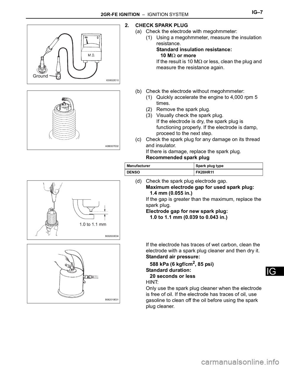
2. CHECK SPARK PLUG
(a) Check the electrode with megohmmeter:
(1) Using a megohmmeter, measure the insulation
resistance.
Standard insulation resistance:
10 M
or more
If the result is 10 M
or less, clean the plug and
measure the resistance again.
(b) Check the electrode without megohmmeter:
(1) Quickly accelerate the engine to 4,000 rpm 5
times.
(2) Remove the spark plug.
(3) Visually check the spark plug.
If the electrode is dry, the spark plug is
functioning properly. If the electrode is damp,
proceed to the next step.
(c) Check the spark plug for any damage on its thread
and insulator.
If there is damage, replace the spark plug.
Recommended spark plug
(d) Check the spark plug electrode gap.
Maximum electrode gap for used spark plug:
1.4 mm (0.055 in.)
If the gap is greater than the maximum, replace the
spark plug.
Electrode gap for new spark plug:
1.0 to 1.1 mm (0.039 to 0.043 in.)
If the electrode has traces of wet carbon, clean the
electrode with a spark plug cleaner and then dry it.
Standard air pressure:
588 kPa (6 kgf/cm
2, 85 psi)
Standard duration:
20 seconds or less
HINT:
Only use the spark plug cleaner when the electrode
is free of oil. If the electrode has traces of oil, use
gasoline to clean off the oil before using the spark
plug cleaner.
I039522E10
A088307E02
Manufacturer Spark plug type
DENSO FK20HR11
B002630E04
B062019E01
Page 976 of 2000

AX–144U140F AUTOMATIC TRANSAXLE – DIFFERENTIAL OIL SEAL
AX
REPLACEMENT
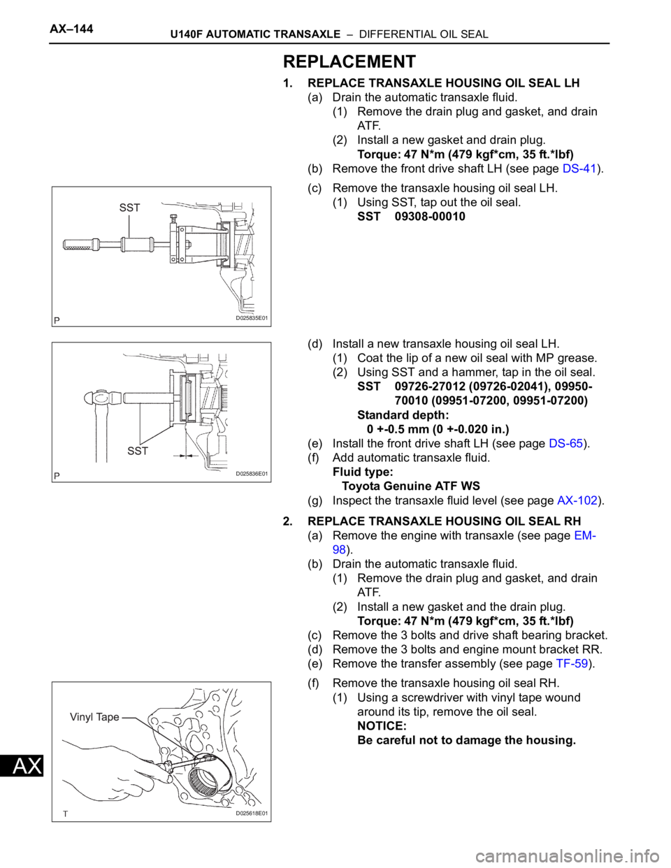
1. REPLACE TRANSAXLE HOUSING OIL SEAL LH
(a) Drain the automatic transaxle fluid.
(1) Remove the drain plug and gasket, and drain
AT F.
(2) Install a new gasket and drain plug.
Torque: 47 N*m (479 kgf*cm, 35 ft.*lbf)
(b) Remove the front drive shaft LH (see page DS-41).
(c) Remove the transaxle housing oil seal LH.
(1) Using SST, tap out the oil seal.
SST 09308-00010
(d) Install a new transaxle housing oil seal LH.
(1) Coat the lip of a new oil seal with MP grease.
(2) Using SST and a hammer, tap in the oil seal.
SST 09726-27012 (09726-02041), 09950-
70010 (09951-07200, 09951-07200)
Standard depth:
0 +-0.5 mm (0 +-0.020 in.)
(e) Install the front drive shaft LH (see page DS-65).
(f) Add automatic transaxle fluid.
Fluid type:
Toyota Genuine ATF WS
(g) Inspect the transaxle fluid level (see page AX-102).
2. REPLACE TRANSAXLE HOUSING OIL SEAL RH
(a) Remove the engine with transaxle (see page EM-
98).
(b) Drain the automatic transaxle fluid.
(1) Remove the drain plug and gasket, and drain
AT F.
(2) Install a new gasket and the drain plug.
Torque: 47 N*m (479 kgf*cm, 35 ft.*lbf)
(c) Remove the 3 bolts and drive shaft bearing bracket.
(d) Remove the 3 bolts and engine mount bracket RR.
(e) Remove the transfer assembly (see page TF-59).
(f) Remove the transaxle housing oil seal RH.
(1) Using a screwdriver with vinyl tape wound
around its tip, remove the oil seal.
NOTICE:
Be careful not to damage the housing.
D025835E01
D025836E01
D025618E01