2006 SUZUKI SX4 Output position sensor
[x] Cancel search: Output position sensorPage 1322 of 1556

Downloaded from www.Manualslib.com manuals search engine 9B-3 Lighting Systems:
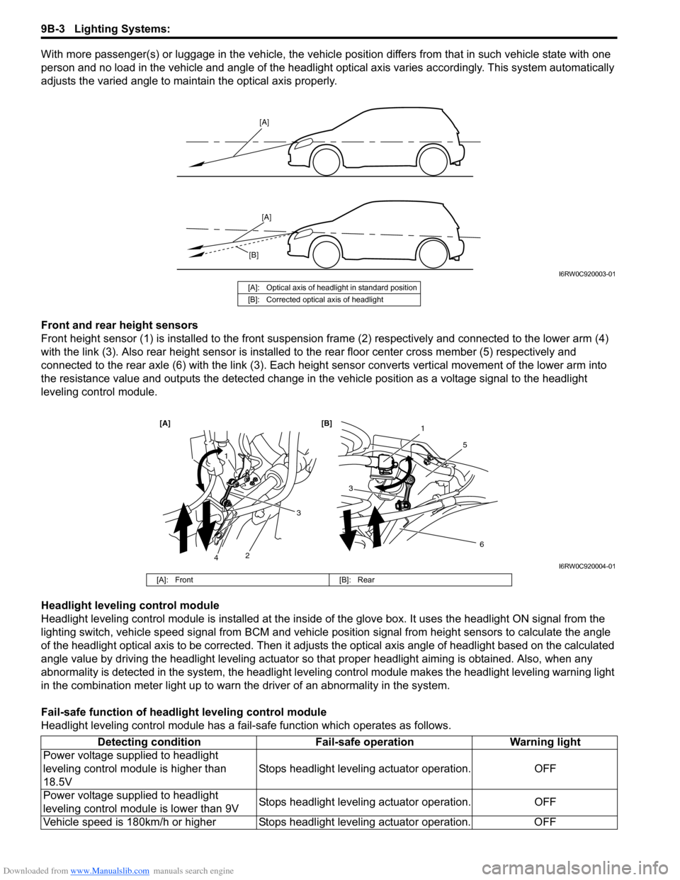
With more passenger(s) or luggage in the vehicle, the vehicle position differs from that in such vehicle state with one
person and no load in the vehicle and angle of the headlight optical axis varies accordingly. This system automatically
adjusts the varied angle to maintain the optical axis properly.
Front and rear height sensors
Front height sensor (1) is installed to the front suspension frame (2) respectively and connected to the lower arm (4)
with the link (3). Also rear height sensor is installed to the rear floor center cross member (5) respectively and
connected to the rear axle (6) with the link (3). Each height sensor converts vertical movement of the lower arm into
the resistance value and outputs the detected change in the vehicle position as a voltage signal to the headlight
leveling control module.
Headlight leveling control module
Headlight leveling control module is installed at the inside of the glove box. It uses the headlight ON signal from the
lighting switch, vehicle speed signal from BCM and vehicle position signal from height sensors to calculate the angle
of the headlight optical axis to be corrected. Then it adjusts the optical axis angle of headlight based on the calculated
angle value by driving the headlight leveling actuator so that proper headlight aiming is obtained. Also, when any
abnormality is detected in the system, the headlight leveling control module makes the headlight leveling warning light
in the combination meter light up to warn the driver of an abnormality in the system.
Fail-safe function of headlight leveling control module
Headlight leveling control module has a fail-safe function which operates as follows.
[A]
[A]
[B]
I6RW0C920003-01
[A]: Optical axis of headlight in standard position
[B]: Corrected optical axis of headlight
1
5
[A] [B]
6
3
1
2
3
4I6RW0C920004-01
[A]: Front [B]: Rear
Detecting condition Fail-safe operation Warning light
Power voltage supplied to headlight
leveling control module is higher than
18.5VStops headlight leveling actuator operation. OFF
Power voltage supplied to headlight
leveling control module is lower than 9VStops headlight leveling actuator operation. OFF
Vehicle speed is 180km/h or higher Stops headlight leveling actuator operation. OFF
Page 1349 of 1556

Downloaded from www.Manualslib.com manuals search engine Lighting Systems: 9B-30
Height Sensor and Its Circuit Inspection (If
Equipped)
S6RW0D9206028
1) Remove front or rear height sensor from vehicle
referring to “Height Sensor Removal and Installation
(If Equipped)”.
2) Connect connector to height sensor.
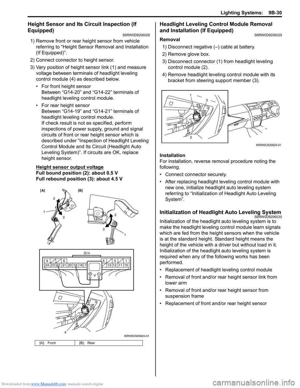
3) Vary position of height sensor link (1) and measure
voltage between terminals of headlight leveling
control module (4) as described below.
• For front height sensor
Between “G14-20” and “G14-22” terminals of
headlight leveling control module.
• For rear height sensor
Between “G14-19” and “G14-21” terminals of
headlight leveling control module.
If check result is not as specified, perform
inspections of power supply, ground and signal
circuits of front or rear height sensor which is
described under “Inspection of Headlight Leveling
Control Module and Its Circuit (Headlight Auto
Leveling System)”. If circuits are OK, replace
height sensor.
Height sensor output voltage
Full bound position (2): about 0.5 V
Full rebound position (3): about 4.5 V
Headlight Leveling Control Module Removal
and Installation (If Equipped)
S6RW0D9206029
Removal
1) Disconnect negative (–) cable at battery.
2) Remove glove box.
3) Disconnect connector (1) from headlight leveling
control module (2).
4) Remove headlight leveling control module with its
bracket from steering support member (3).
Installation
For installation, reverse removal procedure noting the
following.
• Connect connector securely.
• After replacing headlight leveling control module with
new one, initialize headlight auto leveling system
referring to “Initialization of Headlight Auto Leveling
System”.
Initialization of Headlight Auto Leveling SystemS6RW0D9206030
Initialization of the headlight auto leveling system is to
make the headlight leveling control module learn signals
which are fed from the height sensors when the vehicle
is at the standard height. Standard height means the
height of the vehicle with a driver but without load in it.
Initialization of the headlight auto leveling system is
required when any of the following works has been
performed.
• Replacement of headlight leveling control module
• Removal of front and/or rear height sensor link from
lower arm
• Removal of front and/or rear height sensor from
suspension frame
• Replacement of front and/or rear height sensor
[A]: Front [B]: Rear
[A] [B]
4
G14
10 11 12 13 16 17 18 19 2031 5 6 9
21 22 23 24
V
2
3 1
2
3
1
I6RW0C920024-01
23 1
I6RW0C920025-01
Page 1485 of 1556

Downloaded from www.Manualslib.com manuals search engine Body Electrical Control System: 10B-12
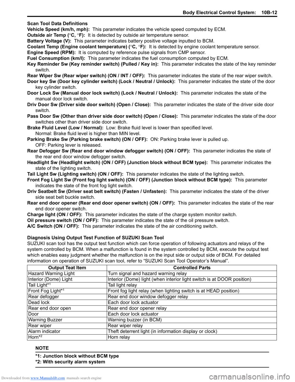
Scan Tool Data Definitions
Vehicle Speed (km/h, mph): This parameter indicates the vehicle speed computed by ECM.
Outside air Temp (°C, °F): It is detected by outside air temperature sensor.
Battery Voltage (V): This parameter indicates battery positive voltage inputted to BCM.
Coolant Temp (Engine coolant temperature) (°C, °F): It is detected by engine coolant temperature sensor.
Engine Speed (RPM): It is computed by reference pulse signals from CMP sensor.
Fuel Consumption (km/l): This parameter indicates the fuel consumption computed by ECM.
Key Reminder Sw (Key reminder switch) (Pulled / Key in): This parameter indicates the state of the key reminder
switch.
Rear Wiper Sw (Rear wiper switch) (ON / INT / OFF): This parameter indicates the state of the rear wiper switch.
Door key Sw (Door key cylinder switch) (Lock / Neutral / Unlock): This parameter indicates the state of the door
key cylinder switch.
Door Lock Sw (Manual door lock switch) (Lock / Neutral / Unlock): This parameter indicates the state of the
manual door lock switch.
Driv Door Sw (Driver side door switch) (Open / Close): This parameter indicates the state of the driver side door
switch.
Pass Door Sw (Other than driver side door switch) (Open / Close): This parameter indicates the state of the door
switches other than driver side door switch.
Brake Fluid Level (Low / Normal): Low: Brake fluid level is lower than specified level.
Normal: Brake fluid level is higher than MIN level.
Parking Brake Sw (Parking brake switch) (ON / OFF): ON: Parking brake lever is pulled up.
OFF: Parking lever is released.
Rear Defogger Sw (Rear end door window defogger switch) (ON / OFF): This parameter indicates the state of
the rear end door window defogger switch.
Headlight Sw (Headlight switch) (ON / OFF) (Junction block without BCM type): This parameter indicates the
state of the lighting switch.
Tail Light Sw (Lighting switch) (ON / OFF): This parameter indicates the state of the lighting switch.
Front Fog Light Sw (Front fog light switch) (ON / OFF) (Junction block without BCM type): This parameter
indicates the state of the front fog light switch.
Driv Seatbelt Sw (Driver seat belt switch) (Fasten / Unfasten): This parameter indicates the state of the driver
side seat belt buckle switch.
Rear end door opener (Rear end door opener switch) (ON / OFF): This parameter indicates the state of the rear
end door opener switch.
Charge light (ON / OFF): This parameter indicates the state of the charge system monitor switch.
Oil pressure switch (ON / OFF): This parameter indicates the state of the oil pressure switch.
A/C Switch (ON / OFF): This parameter indicates the state of the air conditioning switch.
Diagnosis Using Output Test Function of SUZUKI Scan Tool
SUZUKI scan tool has the output test function which can force operation of following actuators and relays of the
system controlled by BCM. When a malfunction is found in the system controlled by BCM, execute the output test
which enables easy judgment whether the malfunction is on the input side or output side of BCM. For detailed
information on operation of SUZUKI scan tool, refer to “SUZUKI Scan Tool Operator’s Manual”.
NOTE
*1: Junction block without BCM type
*2: With security alarm system
Output Teat Item Controlled Parts
Hazard Warning Light Turn signal and hazard warning relay
Interior (Dome) Light Interior (Dome) light (when interior light switch is at DOOR position)
Tail Light*
1Tail light relay
Front Fog Light*1Front fog light relay (when lighting switch is at HEAD position)
Rear defogger Rear end door window defogger relay
Dead lock Each door lock actuator
Rear end door open Rear end door opener relay
Door Each door lock actuator
Warning Buzzer Warning buzzer (in BCM)
Rear wiper Rear wiper relay
Alarm indicator Theft deterrent light (in information display or clock)
Horn*
2Horn relay
Page 1495 of 1556

Downloaded from www.Manualslib.com manuals search engine Body Electrical Control System: 10B-22
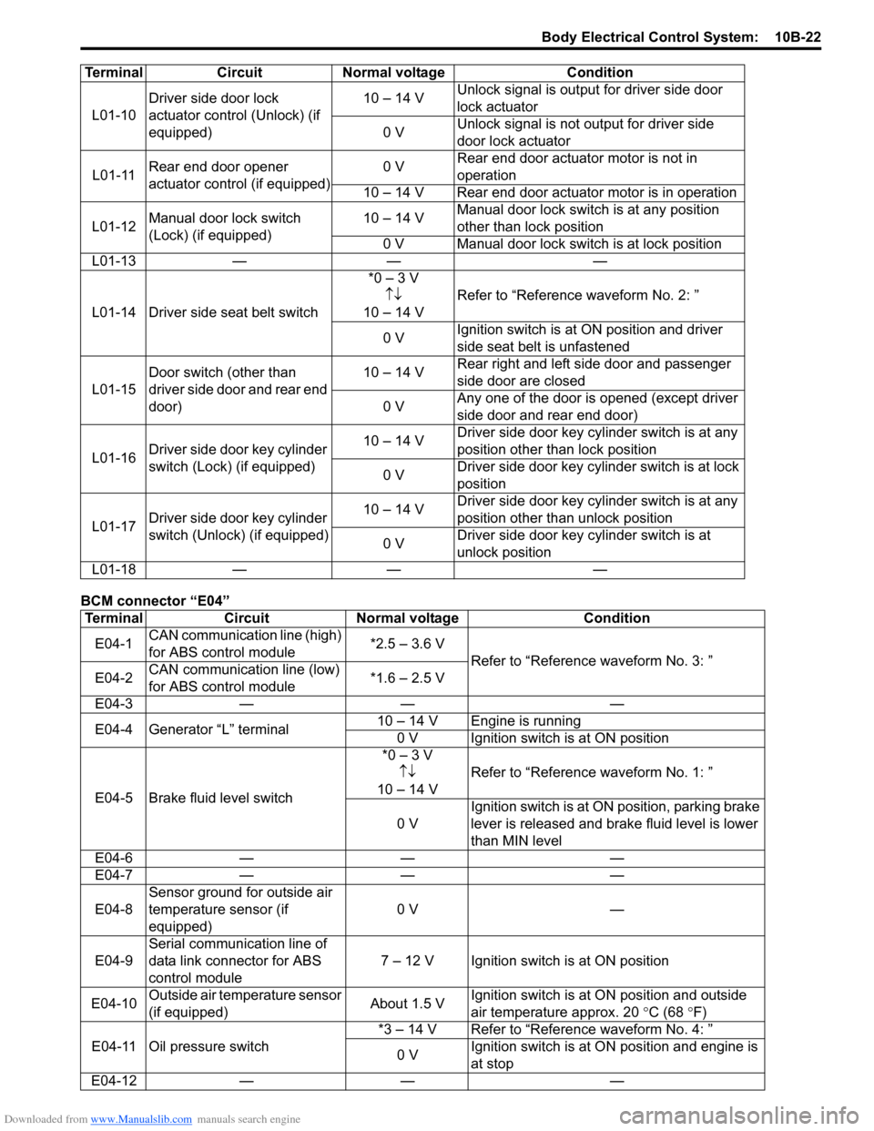
BCM connector “E04”L01-10Driver side door lock
actuator control (Unlock) (if
equipped)10 – 14 VUnlock signal is output for driver side door
lock actuator
0 VUnlock signal is not output for driver side
door lock actuator
L01-11Rear end door opener
actuator control (if equipped)0 VRear end door actuator motor is not in
operation
10 – 14 V Rear end door actuator motor is in operation
L01-12Manual door lock switch
(Lock) (if equipped)10 – 14 VManual door lock switch is at any position
other than lock position
0 V Manual door lock switch is at lock position
L01-13 — — —
L01-14 Driver side seat belt switch*0 – 3 V
↑↓
10 – 14 VRefer to “Reference waveform No. 2: ”
0 VIgnition switch is at ON position and driver
side seat belt is unfastened
L01-15Door switch (other than
driver side door and rear end
door)10 – 14 VRear right and left side door and passenger
side door are closed
0 VAny one of the door is opened (except driver
side door and rear end door)
L01-16Driver side door key cylinder
switch (Lock) (if equipped)10 – 14 VDriver side door key cylinder switch is at any
position other than lock position
0 VDriver side door key cylinder switch is at lock
position
L01-17Driver side door key cylinder
switch (Unlock) (if equipped)10 – 14 VDriver side door key cylinder switch is at any
position other than unlock position
0 VDriver side door key cylinder switch is at
unlock position
L01-18 — — —
Terminal Circuit Normal voltage Condition
E04-1CAN communication line (high)
for ABS control module*2.5 – 3.6 V
Refer to “Reference waveform No. 3: ”
E04-2CAN communication line (low)
for ABS control module*1.6 – 2.5 V
E04-3 — — —
E04-4 Generator “L” terminal10 – 14 V Engine is running
0 V Ignition switch is at ON position
E04-5 Brake fluid level switch*0 – 3 V
↑↓
10 – 14 VRefer to “Reference waveform No. 1: ”
0 VIgnition switch is at ON position, parking brake
lever is released and brake fluid level is lower
than MIN level
E04-6 — — —
E04-7 — — —
E04-8Sensor ground for outside air
temperature sensor (if
equipped)0 V —
E04-9Serial communication line of
data link connector for ABS
control module7 – 12 V Ignition switch is at ON position
E04-10Outside air temperature sensor
(if equipped)About 1.5 VIgnition switch is at ON position and outside
air temperature approx. 20 °C (68
°F)
E04-11 Oil pressure switch*3 – 14 V Refer to “Reference waveform No. 4: ”
0 VIgnition switch is at ON position and engine is
at stop
E04-12 — — — Terminal Circuit Normal voltage Condition