2006 SUZUKI SX4 Output position sensor
[x] Cancel search: Output position sensorPage 912 of 1556

Downloaded from www.Manualslib.com manuals search engine 6C-32 Power Assisted Steering System:
NOTE
*: The voltage of this circuit may not be checked by voltmeter. If so, use oscilloscope.
Reference waveform No.1
Motor output signal 1(1), Motor output signal 2(2), with
engine idlingE11-20 REDReference sensor power supply
for torque sensorAbout 3.0 – 3.5 V• Ignition switch ON
• Check voltage between “E11-20” and
“E11-9” terminals
E12-1 BLK Motor output 1*0 – 1 V
↑↓
10 – 14 V
(“Reference
waveform No.1: ”,
“Reference
waveform No.2: ”
and “Reference
waveform No.3: ”)• Engine idling and steering wheel at
straight position
• Voltage between “E12-1” and vehicle
body ground
E12-2 RED Motor output 2*0 – 1 V
↑↓
10 – 14 V
(“Reference
waveform No.1: ”,
“Reference
waveform No.2: ”
and “Reference
waveform No.3: ”)• Engine idling and steering wheel at
straight position
• Voltage between “E12-2” and vehicle
body ground
E13-1 GRNMain power supply for internal
memory and P/S motor10 – 14 V —
E13-2 BLK Ground for P/S control module Below 0.3 V — Terminal Wire color Circuit Normal voltage Condition
Measurement
terminalCH1: “E12-1” to vehicle body ground
CH1: “E12-2” to vehicle body ground
Oscilloscope
settingCH1: 5 V/DIV, CH2: 5 V/DIV
TIME: 20 µs/DIV
Measurement
condition• Engine is idling and steering
wheel at straight position
I6RS0B630017-01
Page 923 of 1556

Downloaded from www.Manualslib.com manuals search engine Power Assisted Steering System: 6C-43
8) Using ammeter (2), check that P/S motor current (1)
is as following table with idling engine. If check result
is not satisfactory, check P/S control module for
torque sensor signal and P/S motor output referring
to “Inspection of P/S Control Module and Its
Circuits”. If they are OK, replace steering gear case
assembly.
NOTE
When P/S motor is cold condition (that is,
armature coil of P/S motor is not heated),
motor current in the following table can be
measured
Motor current at hoisted vehicle (reference
value)
Specifications
Tightening Torque SpecificationsS6RW0D6307001
NOTE
The specified tightening torque is also described in the following.
“Steering Gear Case Assembly Components”
Reference:
For the tightening torque of fastener not specified in this section, refer to “Fasteners Information in Section 0A”. ConditionWhen
steering
wheel is left
at straight
position: [A]When steering
wheel is turned
left or right by
turning speed
with 90° /sec:
[B]When
steering
wheel is
kept fully
turned left
or right
until it
stops.: [C]
Motor
currentApprox. 0 A Approx. 0 – 5 AApprox.
45 – 60 A
3. P/S control module
1
32
E12-1
E12-2
[C][A]
[B] [B]
I7RW01632012-01
Fastening partTightening torque
Note
N⋅mkgf-mlb-ft
Tie-rod end nut 45 4.5 32.5�)
Tie-rod end lock nut 45 4.5 32.5�)
Wheel bolt 85 8.5 61.5�)
Steering gear case mounting bolt 70 7.0 51.0�)
Steering lower shaft assembly upper joint bolt 25 2.5 18.5�)
Steering lower shaft assembly lower joint bolt 25 2.5 18.5�)
Tie-rod 75 7.5 54.5�)
Earth cable bolt 4.0 0.4 2.8�)
Rack damper screw Tighten 25 N⋅m (2.5 kgf-m, 18.0 lb-ft) and
loosen 180° and then tighten 3.9 N⋅m (0.39
kgf-m, 3.0 lb-ft) and turn it back by 10° or
less by the specified procedure.�)
Rotation torque of pinion 2.2 0.22 1.5�)
Steering rack damper lock nut 60 6.0 43.5�)
Page 979 of 1556

Downloaded from www.Manualslib.com manuals search engine Air Conditioning System: Automatic Type 7B-39
General Description
Auto A/C System DescriptionS6RW0D7221001
The automatic type air conditioning system (auto A/C) is provided with the function to automatically control the inside
air temperature, fan speed, air flow outlet direction and air intake position by HVAC control module in addition to
functions of the manual type air conditioning system (manual A/C). Once the inside air temperature is set using the
temperature selector, HVAC control module automatically controls the inside air temperature at the constant level at all
times based on the inside air temperature, outside air temperature, amount of sunlight and engine coolant
temperature detected respectively by the inside air temperature sensor, outside air temperature sensor, sunload
sensor and ECT sensor. For the electronic control system components location, refer to “Electronic Control System
Components Location”. For the A/C system components location, refer to “A/C System Major Components Location”.
Auto A/C Electronic Control Input / Output Table
Temperature selector
MODE (air flow) selector
Blower speed selector
Air intake selector
AUTO switch A/C switch
Outside air
temperature
sensor
A/C refrigerant pressure sensor
Compressor relay
Blower motor controller
Temperature control actuator
Air flow control actuator
Air intake control actuator
BCM
ECM
Data link connector
HVAC control module
CPU
ECT sensor
Sunload sensor
Inside air temperature sensor
Evaporator temperature sensor
Condenser cooling fan relay
Wheel
speed
sensor
*
*
*
Combination meterABS control module
I6RW0C722001-01
*: CAN communication
Page 980 of 1556

Downloaded from www.Manualslib.com manuals search engine 7B-40 Air Conditioning System: Automatic Type
HVAC Control DescriptionS6RW0D7221002
Temperature Control
HVAC control module calculates the target temperature
control door position based on signals from the
temperature selector, inside air temperature sensor,
outside air temperature sensor and sunload sensor and
controls the temperature control actuator so that the
current position of the temperature control door matches
its target position.
Fan Speed Control
HVAC control module calculates the target blower fan
speed based on signals from the temperature selector,
inside air temperature sensor, outside air temperature
sensor, ECT sensor and sunload sensor, compares it
with the current blower fan speed inputted from the
blower motor controller to control the current blower fan
speed to the target level.
Air Flow Outlet Control
HVAC control module calculates the target temperature
control door position based on signals from the
temperature selector, inside air temperature sensor,
outside air temperature sensor, ECT sensor and sunload
sensor. Using thus obtained target temperature control
door position, it further calculates the target air flow
control door position and controls the air flow control
actuator so that the current air flow control door position
becomes the target position.
Air Intake Position Control
HVAC control module determines the position of the air
intake control door based on signals from the
temperature selector, inside air temperature sensor,
outside air temperature sensor and sunload sensor and
selects any of the following positions by controlling the
position of the air intake control door.
• FRESH position (FRE)
• RECIRCULATION position (REC)
• MIX position (MIX)A/C Compressor Relay Control
HVAC control module outputs A/C switch ON signal to
ECM via BCM when the vehicle state satisfy conditions
described below.
• A/C switch is ON
• Evaporator temperature is higher than specified value
• Evaporator temperature sensor malfunction is not
detected
Communication of ECM and BCM is established by CAN
(Controller Area Network). (For more detail of CAN
communication, refer to “CAN Communication System
Description in Section 1A”).
ECM turns ON the A/C compressor relay when the
vehicle state satisfy conditions described below.
• A/C switch ON signal is inputted
• A/C refrigerant pressure is within specified range
• Engine speed is within specified range
• Engine coolant temperature is lower than specified
value
• Throttle opening is lower than specified value
• Vehicle is not in either state of starting or quick
acceleration
• ECT sensor malfunction is not detected
• A/C refrigerant pressure sensor malfunction is not
detected
Condenser Cooling Fan Relay Control
ECM turn ON the condenser cooling fan relay at the
same time when ECM turn ON the A/C compressor
relay.
Sub-Cool A/C System DescriptionS6RW0D7221003
Refer to “Sub-Cool A/C System Description”.
Page 1017 of 1556

Downloaded from www.Manualslib.com manuals search engine Air Conditioning System: Automatic Type 7B-77
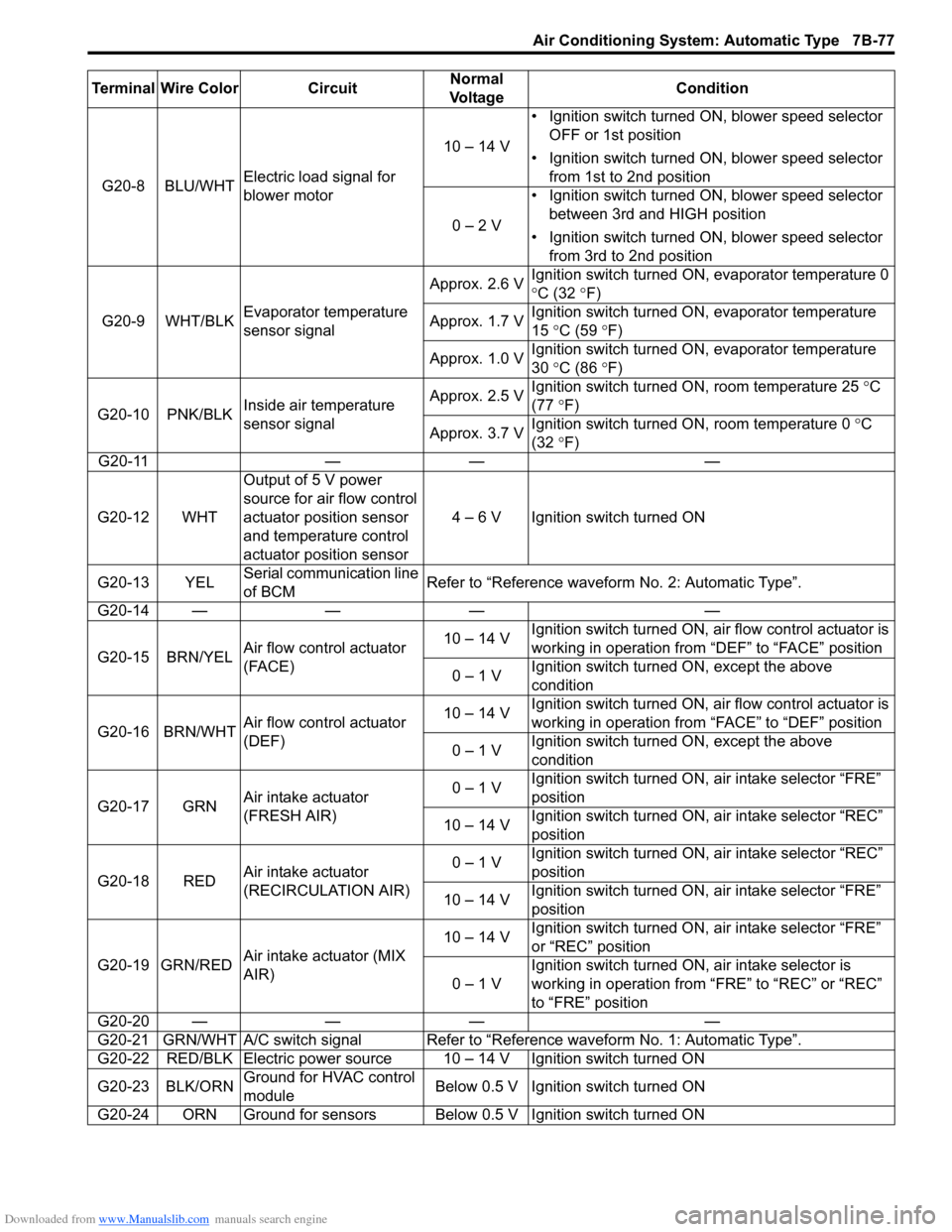
G20-8 BLU/WHTElectric load signal for
blower motor10 – 14 V• Ignition switch turned ON, blower speed selector
OFF or 1st position
• Ignition switch turned ON, blower speed selector
from 1st to 2nd position
0 – 2 V• Ignition switch turned ON, blower speed selector
between 3rd and HIGH position
• Ignition switch turned ON, blower speed selector
from 3rd to 2nd position
G20-9 WHT/BLKEvaporator temperature
sensor signalApprox. 2.6 VIgnition switch turned ON, evaporator temperature 0
°C (32 °F)
Approx. 1.7 VIgnition switch turned ON, evaporator temperature
15 °C (59 °F)
Approx. 1.0 VIgnition switch turned ON, evaporator temperature
30 °C (86 °F)
G20-10 PNK/BLKInside air temperature
sensor signalApprox. 2.5 VIgnition switch turned ON, room temperature 25 °C
(77 °F)
Approx. 3.7 VIgnition switch turned ON, room temperature 0 °C
(32 °F)
G20-11 — — —
G20-12 WHTOutput of 5 V power
source for air flow control
actuator position sensor
and temperature control
actuator position sensor4 – 6 V Ignition switch turned ON
G20-13 YELSerial communication line
of BCMRefer to “Reference waveform No. 2: Automatic Type”.
G20-14 — — — —
G20-15 BRN/YELAir flow control actuator
(FACE)10 – 14 VIgnition switch turned ON, air flow control actuator is
working in operation from “DEF” to “FACE” position
0 – 1 VIgnition switch turned ON, except the above
condition
G20-16 BRN/WHTAir flow control actuator
(DEF)10 – 14 VIgnition switch turned ON, air flow control actuator is
working in operation from “FACE” to “DEF” position
0 – 1 VIgnition switch turned ON, except the above
condition
G20-17 GRNAir intake actuator
(FRESH AIR)0 – 1 VIgnition switch turned ON, air intake selector “FRE”
position
10 – 14 VIgnition switch turned ON, air intake selector “REC”
position
G20-18 REDAir intake actuator
(RECIRCULATION AIR)0 – 1 VIgnition switch turned ON, air intake selector “REC”
position
10 – 14 VIgnition switch turned ON, air intake selector “FRE”
position
G20-19 GRN/REDAir intake actuator (MIX
AIR)10 – 14 VIgnition switch turned ON, air intake selector “FRE”
or “REC” position
0 – 1 VIgnition switch turned ON, air intake selector is
working in operation from “FRE” to “REC” or “REC”
to “FRE” position
G20-20 — — — —
G20-21 GRN/WHT A/C switch signal Refer to “Reference waveform No. 1: Automatic Type”.
G20-22 RED/BLK Electric power source 10 – 14 V Ignition switch turned ON
G20-23 BLK/ORNGround for HVAC control
moduleBelow 0.5 V Ignition switch turned ON
G20-24 ORN Ground for sensors Below 0.5 V Ignition switch turned ON Terminal Wire Color CircuitNormal
Vo l ta g eCondition
Page 1182 of 1556

Downloaded from www.Manualslib.com manuals search engine 9A-15 Wiring Systems:
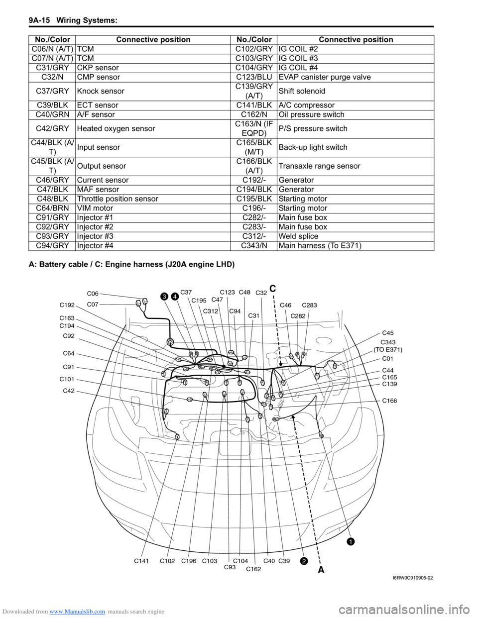
A: Battery cable / C: Engine harness (J20A engine LHD)C06/N (A/T) TCM C102/GRY IG COIL #2
C07/N (A/T) TCM C103/GRY IG COIL #3
C31/GRY CKP sensor C104/GRY IG COIL #4
C32/N CMP sensor C123/BLU EVAP canister purge valve
C37/GRY Knock sensorC139/GRY
(A/T)Shift solenoid
C39/BLK ECT sensor C141/BLK A/C compressor
C40/GRN A/F sensor C162/N Oil pressure switch
C42/GRY Heated oxygen sensorC163/N (IF
EQPD)P/S pressure switch
C44/BLK (A/
T)Input sensorC165/BLK
(M/T)Back-up light switch
C45/BLK (A/
T)Output sensorC166/BLK
(A/T)Transaxle range sensor
C46/GRY Current sensor C192/- Generator
C47/BLK MAF sensor C194/BLK Generator
C48/BLK Throttle position sensor C195/BLK Starting motor
C64/BRN VIM motor C196/- Starting motor
C91/GRY Injector #1 C282/- Main fuse box
C92/GRY Injector #2 C283/- Main fuse box
C93/GRY Injector #3 C312/- Weld splice
C94/GRY Injector #4 C343/N Main harness (To E371) No./Color Connective position No./Color Connective position
C42
C101
C91
C64 C92
C194 C163
C141C102C196 C192
C195
C312
C93C104C103
C94C31C32
C40
C162
C39
C123C48C37
C47
C282
C283C46
C343
(TO E371)
C01
C45
C07
C06
C139 C44
C165
C166
3
2
1
4C
A
I6RW0C910905-02
Page 1183 of 1556

Downloaded from www.Manualslib.com manuals search engine Wiring Systems: 9A-16
C: Engine harness
E: Main harness (RHD)No./Color Connective position No./Color Connective position
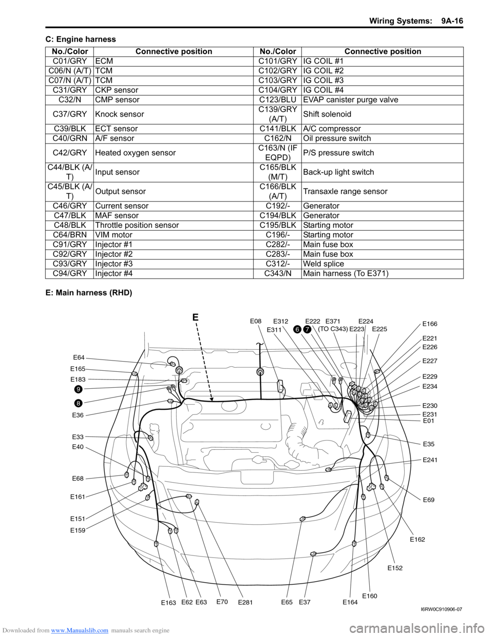
C01/GRY ECM C101/GRY IG COIL #1
C06/N (A/T) TCM C102/GRY IG COIL #2
C07/N (A/T) TCM C103/GRY IG COIL #3
C31/GRY CKP sensor C104/GRY IG COIL #4
C32/N CMP sensor C123/BLU EVAP canister purge valve
C37/GRY Knock sensorC139/GRY
(A/T)Shift solenoid
C39/BLK ECT sensor C141/BLK A/C compressor
C40/GRN A/F sensor C162/N Oil pressure switch
C42/GRY Heated oxygen sensorC163/N (IF
EQPD)P/S pressure switch
C44/BLK (A/
T)Input sensorC165/BLK
(M/T)Back-up light switch
C45/BLK (A/
T)Output sensorC166/BLK
(A/T)Transaxle range sensor
C46/GRY Current sensor C192/- Generator
C47/BLK MAF sensor C194/BLK Generator
C48/BLK Throttle position sensor C195/BLK Starting motor
C64/BRN VIM motor C196/- Starting motor
C91/GRY Injector #1 C282/- Main fuse box
C92/GRY Injector #2 C283/- Main fuse box
C93/GRY Injector #3 C312/- Weld splice
C94/GRY Injector #4 C343/N Main harness (To E371)
E68
E40
E33
E165
E36
E161
E151
E159
E70E281E163E62E63E65E37E164
E64
E183
E08
E311
E312E222E224E225E223
E221
E371
(TO C343)E166
E227
E229
E234
E230
E01
E35
E241
E69
E162
E152
E160
E231
E226
8
9
76
E
I6RW0C910906-07
Page 1320 of 1556

Downloaded from www.Manualslib.com manuals search engine 9B-1 Lighting Systems:
Body, Cab and Accessories
Lighting Systems
Precautions
Precautions for Discharge Headlight Service (If Equipped)S6RW0D9200001
WARNING!
• Do not touch igniter or ballast when lighting switch is at “HEAD” position to avoid possible electric
shock.
• Do not measure voltage or resistance with tester connected to output connector of ballast or igniter
to avoid possible electric shock.
• Do not perform work where exposed to water including rain or with wet hands to avoid possible
electric shock.
• Disassembling igniter or ballast is strictly prohibited as it may cause an electric shock.
• Before inspecting or repairing discharge headlight or its peripheral parts, make sure that lighting
switch is at OFF position and battery is disconnected at negative terminal to avoid possible
electrical shock.
• Do not set lighting switch to “HEAD” position with connector disconnected or any part removed to
avoid possible electric shock.
• Do not touch glass surface of headlight bulb. Oil or grease attached on it may not only make bulb
service life shorter but also cause bulb to burst when lighting switch is turned on.
• Mercury, metal iodide and xenon gas are sealed in discharge headlight bulb. Be sure to dispose of
used discharge headlight bulb properly according to applicable rules or regulations.
Precautions in Diagnosing Troubles (Headlight Auto Leveling System)S6RW0D9200002
• Be sure to read “Air Bag Warning in Section 00” before inspection and observe what is written there.
• Replacement of height sensor and headlight leveling control module. When height sensor and/or headlight leveling
control module is replaced with new one, perform initialization of headlight auto leveling system according to
“Initialization of Headlight Auto Leveling System”.
General Description
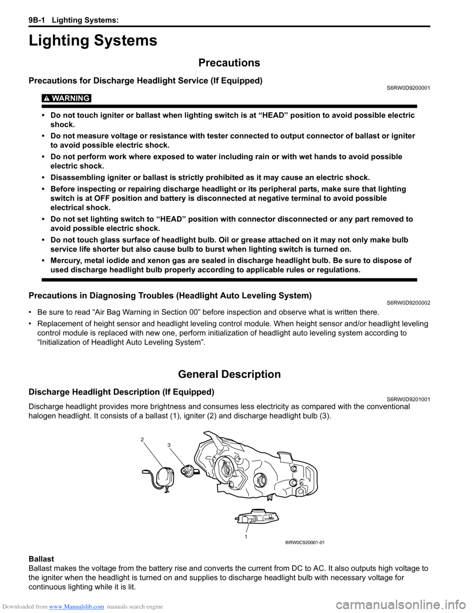
Discharge Headlight Description (If Equipped)S6RW0D9201001
Discharge headlight provides more brightness and consumes less electricity as compared with the conventional
halogen headlight. It consists of a ballast (1), igniter (2) and discharge headlight bulb (3).
Ballast
Ballast makes the voltage from the battery rise and converts the current from DC to AC. It also outputs high voltage to
the igniter when the headlight is turned on and supplies to discharge headlight bulb with necessary voltage for
continuous lighting while it is lit.
2
1 3
I6RW0C920001-01