2006 SUZUKI SX4 Output position sensor
[x] Cancel search: Output position sensorPage 272 of 1556

Downloaded from www.Manualslib.com manuals search engine 1C-4 Engine Electrical Devices:
Throttle Position Sensor Performance Check
1) Remove air cleaner outlet hose.
2) Turn OFF ignition switch.
3) Disconnect connector from electric throttle body
assembly.
4) Check throttle position sensor (main and sub) output
voltage as following steps.
a) For throttle position sensor (main), arrange 3
new 1.5 V batteries (1) in series (check that total
voltage is 4.5 – 5.0 V) and connect its positive
terminal to “Vin” terminal (2) and negative
terminal to “Ground” terminal (3) of sensor. Then
using voltmeter, connect positive terminal to
“Vout 1” terminal (4) of sensor and negative
terminal to battery.
b) For throttle position sensor (sub), arrange 3 new
1.5 V batteries (1) in series (check that total
voltage is 4.5 – 5.0 V) and connect its positive
terminal to “Vin” terminal (2) and negative
terminal to “Ground” terminal (3) of sensor. Then
using voltmeter, connect positive terminal to
“Vout 2” terminal (4) of sensor and negative
terminal to battery.
c) Measure output voltage variation while throttle
valve is opened and closed as following
specification.If sensor voltage is out of specified value and linear
variation as the following graph, replace electric throttle
body assembly.
TP sensor output voltage
TP sensor (main) [A]: 0.45 – 4.88 V, varying
according to throttle valve opening by finger
(Voltage should vary by 0.04 V for each 1° valve
opening)
TP sensor (sub) [B]: 1.33 – 5.007 V, varying
according to throttle valve opening by finger
(Voltage should vary by about 0.032 V for each 1°
valve opening)
1 42 3
I4RS0B130007-02
1
3
24
I4RS0B130008-01
[C]: TP sensor (main) output voltage
[D]: TP sensor (sub) output voltage
[E]: Throttle valve opening
[F]: Position where throttle valve is open by 7° from completely closed
position (default position)
[G]: Angel obtained when accelerator pedal is depressed fully (84°)
[H]: Angle obtained when throttle valve is fully opened with finger (96°)
[B]
[A][D]
(V) [C]
(V)
[F]
[G][E] 0.45 - 0.75 0.724 - 1.036 3.675 - 4.245 4.000 - 4.880
1.33 - 1.63 1.604 - 1.9163.883 - 4.453 4.097 - 5.007
[H]
I7RW01130019-05
Page 274 of 1556

Downloaded from www.Manualslib.com manuals search engine 1C-6 Engine Electrical Devices:
Removal
1) Disconnect negative cable at battery.
2) Disconnect connector from APP sensor assembly.
3) Remove APP sensor assembly from its bracket.
Installation
Reverse removal procedure for installation noting the
following.
• Tighten APP sensor assembly upper nut (1) first and
then lower nuts (2) to specified torque.
Tightening torque
APP sensor assembly nut (a): 6 N⋅m (0.6 kgf-m, 4.5
lb-ft)
• Connect connector to APP sensor assembly securely.
Accelerator Pedal Position (APP) Sensor
Assembly Inspection
S6RW0D1306007
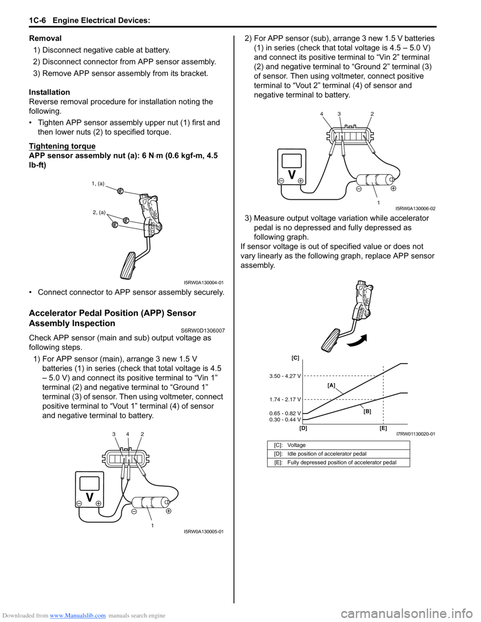
Check APP sensor (main and sub) output voltage as
following steps.
1) For APP sensor (main), arrange 3 new 1.5 V
batteries (1) in series (check that total voltage is 4.5
– 5.0 V) and connect its positive terminal to “Vin 1”
terminal (2) and negative terminal to “Ground 1”
terminal (3) of sensor. Then using voltmeter, connect
positive terminal to “Vout 1” terminal (4) of sensor
and negative terminal to battery.2) For APP sensor (sub), arrange 3 new 1.5 V batteries
(1) in series (check that total voltage is 4.5 – 5.0 V)
and connect its positive terminal to “Vin 2” terminal
(2) and negative terminal to “Ground 2” terminal (3)
of sensor. Then using voltmeter, connect positive
terminal to “Vout 2” terminal (4) of sensor and
negative terminal to battery.
3) Measure output voltage variation while accelerator
pedal is no depressed and fully depressed as
following graph.
If sensor voltage is out of specified value or does not
vary linearly as the following graph, replace APP sensor
assembly.
1, (a)
2, (a)
I5RW0A130004-01
1 2 34I5RW0A130005-01
[C]: Voltage
[D]: Idle position of accelerator pedal
[E]: Fully depressed position of accelerator pedal
1 2 3 4I5RW0A130006-02
[C]
[D] [E]
3.50 - 4.27 V
1.74 - 2.17 V
0.65 - 0.82 V
0.30 - 0.44 V
[A]
[B]
I7RW01130020-01
Page 477 of 1556

Downloaded from www.Manualslib.com manuals search engine Table of Contents 3- i
3
Section 3
CONTENTS
Driveline / Axle
Precautions ................................................. 3-1
Precautions............................................................. 3-1
Precautions on Driveline / Axle ............................. 3-1
Drive Shaft / Axle ..................................... 3A-1
Front ......................................................................... 3A-1
General Description ............................................. 3A-1
Front Drive Shaft Construction ............................ 3A-1
Component Location ........................................... 3A-1
Front Drive Shaft Assembly Components
Location ............................................................ 3A-1
Diagnostic Information and Procedures ............ 3A-2
Front Drive Shaft Symptom Diagnosis ................ 3A-2
Repair Instructions .............................................. 3A-2
Front Drive Shaft Components ........................... 3A-2
Front Drive Shaft Assembly On-Vehicle
Inspection.......................................................... 3A-3
Front Drive Shaft Assembly Removal and
Installation ......................................................... 3A-3
Front Drive Shaft Disassembly and
Reassembly ...................................................... 3A-4
Center Shaft and Center Bearing Support
Disassembly and Reassembly (If Equipped) .. 3A-12
Specifications..................................................... 3A-13
Tightening Torque Specifications ...................... 3A-13
Special Tools and Equipment ........................... 3A-14
Recommended Service Material ....................... 3A-14
Special Tool ...................................................... 3A-14
Rear ........................................................................ 3A-15
General Description ........................................... 3A-15
Rear Drive Shaft Construction .......................... 3A-15
Repair Instructions ............................................ 3A-15
Rear Drive Shaft Components .......................... 3A-15
Rear Drive Shaft Assembly Removal and
Installation ....................................................... 3A-16
Rear Drive Shaft Disassembly and
Reassembly .................................................... 3A-16
Specifications..................................................... 3A-18
Tightening Torque Specifications ...................... 3A-18
Special Tools and Equipment ........................... 3A-18
Recommended Service Material ....................... 3A-18
Special Tool ...................................................... 3A-18
Differential ................................................ 3B-1
Precautions...........................................................3B-1
Precaution for Rear Differential Oil Leakage....... 3B-1
Precautions in Diagnosing Trouble ..................... 3B-1
General Description .............................................3B-2
Rear Differential Description ............................... 3B-2
Coupling Description ........................................... 3B-2
4WD Control System Components ..................... 3B-3
4WD Control System Description........................ 3B-4
Function of 4WD Control System Component .... 3B-4
4WD Control System Wiring Circuit Diagram...... 3B-5
Terminal Arrangement of 4WD Control
Module .............................................................. 3B-5
Input / Output Signal Table of 4WD Control
Module .............................................................. 3B-6
On-Board Diagnostic System Description ........... 3B-6
CAN Communication System Description........... 3B-7
Diagnostic Information and Procedures ............3B-8
4WD Control System Check ............................... 3B-8
4WD Position Indicator Operation Check.......... 3B-10
4WD Control System Operation Inspection ...... 3B-10
Visual Inspection ............................................... 3B-11
DTC Check........................................................ 3B-11
DTC Clearance ................................................. 3B-11
DTC Table ......................................................... 3B-12
Fail-Safe Table .................................................. 3B-12
Scan Tool Data ................................................. 3B-13
Rear Differential Symptom Diagnosis ............... 3B-14
4WD Control Symptom Diagnosis..................... 3B-14
4WD Position Indicator Does Not Come ON at
Ignition Switch ON but Engine Stops .............. 3B-15
4WD Position Indicator Remains ON Steady
at Ignition Switch ON....................................... 3B-16
DTC C1240: 4WD Control Module Power
Supply Circuit Malfunction............................... 3B-17
DTC C1243: Internal Circuit Malfunction of
4WD Control Module ....................................... 3B-18
DTC C1250: Coupling Air Temperature
Sensor Circuit Open ........................................ 3B-19
DTC C1251: Coupling Air Temperature
Sensor Circuit Short ........................................ 3B-21
DTC C1252: Coupling Assembly Circuit Open .. 3B-22
DTC C1253: Coupling Assembly Circuit Short .. 3B-24
DTC C1254: 2WD/4WD Switch Malfunction ..... 3B-25
DTC U0073: Control Module Communication
Bus Off ............................................................ 3B-27
Page 503 of 1556

Downloaded from www.Manualslib.com manuals search engine Differential: 3B-6
Input / Output Signal Table of 4WD Control ModuleS6RW0D3201008
4WD control module outputs the following signals to coupling assembly, indicators, according to the 2WD/4WD switch
operation.
On-Board Diagnostic System DescriptionS6RW0D3201009
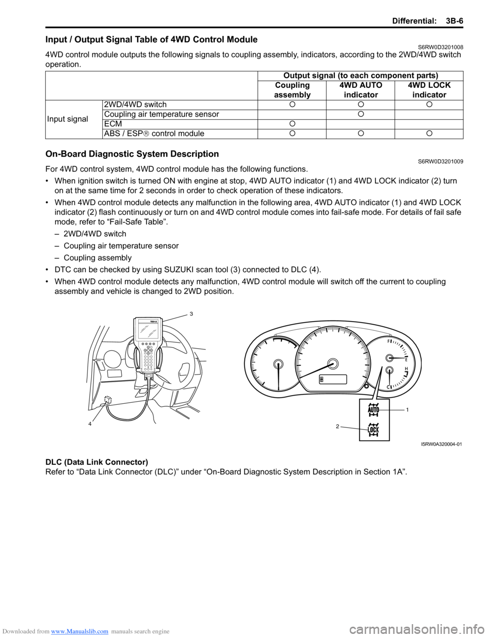
For 4WD control system, 4WD control module has the following functions.
• When ignition switch is turned ON with engine at stop, 4WD AUTO indicator (1) and 4WD LOCK indicator (2) turn
on at the same time for 2 seconds in order to check operation of these indicators.
• When 4WD control module detects any malfunction in the following area, 4WD AUTO indicator (1) and 4WD LOCK
indicator (2) flash continuously or turn on and 4WD control module comes into fail-safe mode. For details of fail safe
mode, refer to “Fail-Safe Table”.
– 2WD/4WD switch
– Coupling air temperature sensor
– Coupling assembly
• DTC can be checked by using SUZUKI scan tool (3) connected to DLC (4).
• When 4WD control module detects any malfunction, 4WD control module will switch off the current to coupling
assembly and vehicle is changed to 2WD position.
DLC (Data Link Connector)
Refer to “Data Link Connector (DLC)” under “On-Board Diagnostic System Description in Section 1A”.Output signal (to each component parts)
Coupling
assembly4WD AUTO
indicator4WD LOCK
indicator
Input signal2WD/4WD switch�{�{�{
Coupling air temperature sensor�{
ECM�{
ABS / ESP® control module�{�{�{
1
2 3
4
I5RW0A320004-01
Page 509 of 1556

Downloaded from www.Manualslib.com manuals search engine Differential: 3B-12
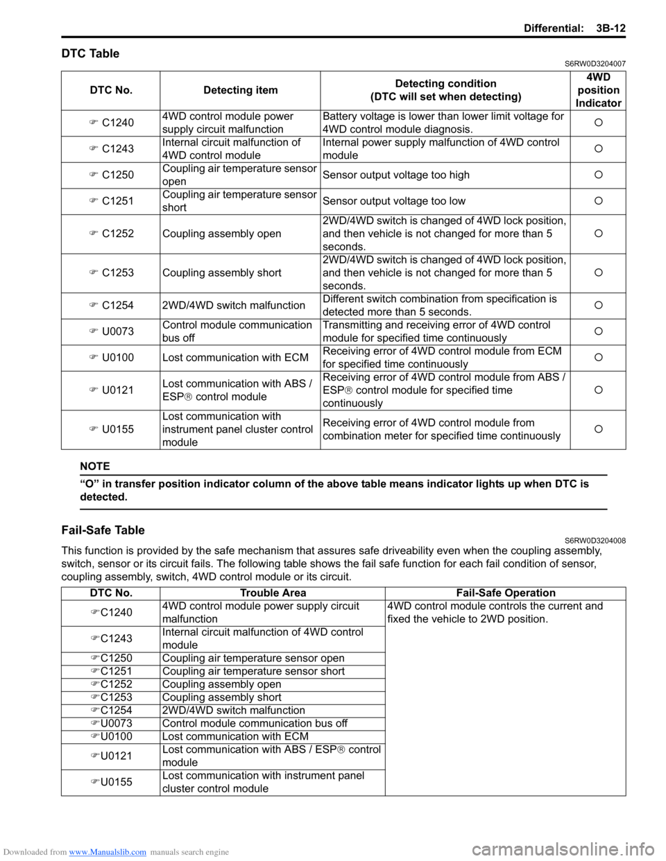
DTC TableS6RW0D3204007
NOTE
“O” in transfer position indicator column of the above table means indicator lights up when DTC is
detected.
Fail-Safe TableS6RW0D3204008
This function is provided by the safe mechanism that assures safe driveability even when the coupling assembly,
switch, sensor or its circuit fails. The following table shows the fail safe function for each fail condition of sensor,
coupling assembly, switch, 4WD control module or its circuit. DTC No. Detecting itemDetecting condition
(DTC will set when detecting)4WD
position
Indicator
�) C12404WD control module power
supply circuit malfunctionBattery voltage is lower than lower limit voltage for
4WD control module diagnosis.�{
�) C1243Internal circuit malfunction of
4WD control moduleInternal power supply malfunction of 4WD control
module�{
�) C1250Coupling air temperature sensor
openSensor output voltage too high�{
�) C1251Coupling air temperature sensor
shortSensor output voltage too low�{
�) C1252 Coupling assembly open2WD/4WD switch is changed of 4WD lock position,
and then vehicle is not changed for more than 5
seconds.�{
�) C1253 Coupling assembly short2WD/4WD switch is changed of 4WD lock position,
and then vehicle is not changed for more than 5
seconds.�{
�) C1254 2WD/4WD switch malfunctionDifferent switch combination from specification is
detected more than 5 seconds.�{
�) U0073Control module communication
bus offTransmitting and receiving error of 4WD control
module for specified time continuously�{
�) U0100 Lost communication with ECMReceiving error of 4WD control module from ECM
for specified time continuously�{
�) U0121Lost communication with ABS /
ESP® control moduleReceiving error of 4WD control module from ABS /
ESP® control module for specified time
continuously�{
�) U0155Lost communication with
instrument panel cluster control
moduleReceiving error of 4WD control module from
combination meter for specified time continuously�{
DTC No. Trouble Area Fail-Safe Operation
�)C12404WD control module power supply circuit
malfunction4WD control module controls the current and
fixed the vehicle to 2WD position.
�)C1243Internal circuit malfunction of 4WD control
module
�)C1250 Coupling air temperature sensor open
�)C1251 Coupling air temperature sensor short
�)C1252 Coupling assembly open
�)C1253 Coupling assembly short
�)C1254 2WD/4WD switch malfunction
�)U0073 Control module communication bus off
�)U0100 Lost communication with ECM
�)U0121Lost communication with ABS / ESP® control
module
�)U0155Lost communication with instrument panel
cluster control module
Page 639 of 1556

Downloaded from www.Manualslib.com manuals search engine ABS: 4E-34
Installation
1) Install hydraulic unit / control module assembly by
reversing removal procedure noting the following.
Install ABS hydraulic unit / control module assembly
bracket bolt as follows.
a) Tighten bracket bolt (1) and (2) by hand.
b) Then tighten bracket bolt to specified torque.
Tightening order (1) → (2)
Tightening torque
Brake pipe flare nut (a): 16 N·m (1.6 kgf-m, 11.5
lb-ft)
ABS hydraulic unit / control module assembly
bolt (b): 9 N·m (0.9 kgf-m, 6.5 lb-ft)
ABS hydraulic unit / control module assembly
bracket bolt (c): 26 N·m (2.6 kgf-m, 19.0 lb-ft)2) Bleed air from brake system referring to “Air
Bleeding of Brake System in Section 4A”.
3) Check each installed part for fluid leakage and
perform “ABS Hydraulic Unit Operation Check”.
NOTE
For new ABS hydraulic unit / control module
assembly, if “ABS Hydraulic Unit Operation
Check” has not been performed, ABS
warning light may flash when ignition switch
is turned ON position.
Accordingly preform “ABS Hydraulic Unit
Operation Check” to stop flashing of ABS
warning light.
Front and Rear Wheel Speed Sensor On-Vehicle
Inspection
S6RW0D4506005
Output Voltage Inspection
1) Disconnect negative (–) cable from battery.
2) Hoist vehicle a little.
3) Disconnect wheel speed sensor connector.
4) Set up measuring device as shown in figure, the
resistance to 115 Ω and the power supply voltage to
12 V.
CAUTION!
Incorrect voltage and/or wrong connection
cause damage to wheel speed sensor.
I6RW0C450011-01
1. Wheel speed sensor connector 4. “BLK” wire terminal
2. Resistance (115Ω) 5. Power supply (12 V)
3. “WHT” wire terminal
V
41
3
2
5
I5JB0A450026-03
Page 646 of 1556

Downloaded from www.Manualslib.com manuals search engine 5-ii Table of Contents
DTC P1723: Range Select Switch
Malfunction ...................................................... 5A-68
DTC P1878: Torque Converter Clutch
Shudder .......................................................... 5A-69
DTC P2762: Torque Converter Clutch (TCC)
Pressure Control Solenoid Control Circuit
Range / Performance ...................................... 5A-70
DTC P2763: Torque Converter Clutch (TCC)
Pressure Control Solenoid Control Circuit
High ................................................................. 5A-72
DTC P2764: Torque Converter Clutch (TCC)
Circuit Pressure Control Solenoid Control
Circuit Low ...................................................... 5A-74
DTC U0073: Control Module Communication
Bus Off ............................................................ 5A-76
DTC U0100: Lost Communication with ECM /
PCM “A” .......................................................... 5A-76
Inspection of TCM and Its Circuits .................... 5A-76
TCM Power and Ground Circuit Check ............. 5A-80
Brake Interlock System Inspection .................... 5A-81
Repair Instructions ............................................5A-82
Learning Control Initialization ............................ 5A-82
A/T Fluid Level Check ....................................... 5A-82
A/T Fluid Change .............................................. 5A-83
Select Lever Components ................................. 5A-84
Select Lever Assembly Removal and
Installation ....................................................... 5A-84
Select Lever Knob Installation........................... 5A-84
Select Lever Inspection ..................................... 5A-85
“3” Position Switch Inspection ........................... 5A-85
Shift Lock Solenoid Inspection .......................... 5A-85
Shift Lock Solenoid Replacement ..................... 5A-85
Select Cable Components ................................ 5A-86
Select Cable Removal and Installation ............. 5A-86
Select Cable Adjustment ................................... 5A-86
Key Interlock Cable Removal and Installation... 5A-87
Transmission Range Sensor Inspection and
Adjustment ...................................................... 5A-89
Output Shaft Speed Sensor (VSS) Removal
and Installation ................................................ 5A-90
Output Shaft Speed Sensor (VSS) Inspection .. 5A-90
Input Shaft Speed Sensor Removal and
Installation ....................................................... 5A-91
Input Shaft Speed Sensor Inspection................ 5A-91
Transmission Fluid Temperature Sensor
Removal and Installation ................................. 5A-91
Transmission Fluid Temperature Sensor
Inspection ........................................................ 5A-92
Solenoid Valves (Shift Solenoid Valves and
Timing Solenoid Valve) Removal and
Installation ....................................................... 5A-92
Solenoid Valves (Shift Solenoid Valves and
Timing Solenoid Valve) Inspection .................. 5A-94
Pressure Control Solenoid Valves (Pressure
Control Solenoid and TCC Solenoid)
Removal and Installation ................................. 5A-95
Pressure Control Solenoid Valves Inspection ... 5A-96
Transmission Control Module (TCM)
Removal and Installation ................................. 5A-97
A/T Relay Inspection ......................................... 5A-97Differential Side Oil Seal Replacement ............. 5A-98
A/T Fluid Cooler Hoses Replacement ............... 5A-98
Automatic Transaxle Unit Components............. 5A-99
Automatic Transaxle Unit Dismounting and
Remounting ................................................... 5A-100
Automatic Transaxle Assembly Components . 5A-102
Automatic Transaxle Unit Disassembly........... 5A-104
Oil Pump Assembly Components ................... 5A-116
Oil Pump Assembly Disassembly and
Reassembly .................................................. 5A-116
Oil Pump Assembly Inspection ....................... 5A-117
Direct Clutch Assembly Components.............. 5A-119
Direct Clutch Assembly Preliminary Check ..... 5A-119
Direct Clutch Assembly Disassembly and
Reassembly .................................................. 5A-120
Direct Clutch Assembly Inspection.................. 5A-122
Forward and Reverse Clutch Assembly
Components .................................................. 5A-123
Forward and Reverse Clutch Assembly
Preliminary Check ......................................... 5A-123
Forward and Reverse Clutch Assembly
Disassembly and Reassembly ...................... 5A-124
Forward and Reverse Clutch Assembly
Inspection ...................................................... 5A-127
2nd Brake Piston Assembly Components ....... 5A-128
2nd Brake Piston Assembly Disassembly and
Reassembly .................................................. 5A-128
Transaxle Rear Cover (O/D and 2nd Coast
Brake Piston) Assembly Components........... 5A-129
Transaxle Rear Cover (O/D and 2nd Coast
Brake Piston) Assembly Disassembly and
Reassembly .................................................. 5A-130
Transaxle Rear Cover (O/D and 2nd Coast
Brake Piston) Assembly Inspection............... 5A-131
Countershaft Assembly Components.............. 5A-132
Countershaft Assembly Disassembly and
Reassembly .................................................. 5A-132
Valve Body Assembly Components ................ 5A-133
Valve Body Assembly Disassembly and
Reassembly .................................................. 5A-134
Differential Assembly Components ................. 5A-135
Differential Assembly Disassembly and
Reassembly .................................................. 5A-136
Differential Assembly Inspection ..................... 5A-137
Torque Converter Housing Disassembly and
Reassembly .................................................. 5A-138
Transaxle Case Disassembly and
Reassembly .................................................. 5A-140
Automatic Transaxle Unit Inspection and
Adjustment .................................................... 5A-141
Automatic Transaxle Unit Assembly ............... 5A-144
Specifications ...................................................5A-161
Tightening Torque Specifications .................... 5A-161
Special Tools and Equipment .........................5A-162
Recommended Service Material ..................... 5A-162
Special Tool .................................................... 5A-162
Manual Transmission/Transaxle ............ 5B-1
General Description .............................................5B-1
Manual Transaxle Construction .......................... 5B-1
Page 658 of 1556

Downloaded from www.Manualslib.com manuals search engine 5A-10 Automatic Transmission/Transaxle:
Schematic and Routing Diagram
Transmission Control Module (TCM) Wiring DiagramS6RW0D5102001
12V
12V
12V
IG1
118
9
10
P
R
N
D
2
L12
2.5V
5V
12V
5V
12V
12V
12V
WHT
BLK
BLK
BLK
BLK
PPLBLK/WHT
BLK/ORN
IG11
RED/BLK
YEL/BLKYEL/BLU
LT GRN/BLK
+BB
WHT/RED
14
20 15
16
17
19
12V18
1 2
3
132126
24 27
28
29
30
65
16 15 14 13 12 1143
24 23 212210 9 8 721
19 20 18 17 C06
17 16
26 2515 14 65 342
13 12
23 22 2411 10 9
21 20 1987
18 1 C07
[A]
22
25
YELYEL/GRN
WHT
P
N
BRN LT/GRN
ORN
BLK/YEL
BLU/BLK
GRY
LT GRN/BLKWHT/BLU
WHT/BLK
C06-11
C06-12
C06-16
C06-15
C06-14
C06-4
C06-2
C06-1
C06-23C06-6 C06-24C06-5
C06-3
RED
GRN GRN/ORNPNK/BLK
GRN/YEL
LT GRN/BLKC07-6
C07-16
C07-23 C07-25
C07-20
C07-1
C07-8
C07-7
C07-19
C07-18
4IG11 23
C07-9
YEL
RED
WHTBLU35 34
3637
5REDWHT
7
WHT
RED
33
4
6
C06-7C06-17WHT
REDREDWHT
WHT
12V12V
WHTRED
WHTREDREDWHT
31
32
RED
WHTRED[B]
[C]
I6RW0D510003-02
1. TCM 15. Shift solenoid valve-A (No.1) 29. “ST SIG” fuse
2. Input shaft speed sensor 16. Shift solenoid valve-B (No.2) 30. “ST” fuse
3. Output shaft speed sensor / VSS 17. Timing solenoid valve 31. MIL
4. ECM 18. TCC solenoid valve 32. Transmission warning light (non-Euro-OBD model)
5. Combination meter 19. Pressure control solenoid valve 33. ABS control module
6. BCM 20. A/T 34. To Data link connector
7. 4WD control module (if equipped) 21. A/T relay 35. To BCM
8. “3” position switch 22. Inhibitor switch (including transmission range
sensor)36. Junction connector
9. Shift lock solenoid 23. Starter motor relay 37. Keyless start control module (if equipped)
10. Brake light switch 24. Ignition switch [A]: Terminal arrangement of TCM connector (viewed
from harness side)
11. Transmission range sensor 25. Starter motor [B]: Junction block with BCM model
12. Backup lamp 26. “DOME” fuse [C]: Junction block without BCM model
13. Data link connector (DLC) 27. “AT” fuse
14. Transmission fluid temperature sensor 28. “IG1 SIG” fuse