2006 SUZUKI SX4 electrical
[x] Cancel search: electricalPage 5 of 1556

Downloaded from www.Manualslib.com manuals search engine 00
0
1
2
3
4
5
6
7
8
9
10
11
Vo l u m e 1
Precautions............................................................... 00-i
Precautions ............................................................ 00-1
General Information ................................................... 0-i
General Information ............................................... 0A-1
Maintenance and Lubrication ................................. 0B-1
Engine ......................................................................... 1-i
Precautions .............................................................. 1-1
Engine General Information and Diagnosis ........... 1A-1
Aux. Emission Control Devices .............................. 1B-1
Engine Electrical Devices....................................... 1C-1
Engine Mechanical ................................................. 1D-1
Engine Lubrication System .................................... 1E-1
Engine Cooling System .......................................... 1F-1
Fuel System ...........................................................1G-1
Ignition System....................................................... 1H-1
Starting System ....................................................... 1I-1
Charging System.....................................................1J-1
Exhaust System ..................................................... 1K-1
Suspension ................................................................. 2-i
Precautions .............................................................. 2-1
Suspension General Diagnosis .............................. 2A-1
Front Suspension ................................................... 2B-1
Rear Suspension.................................................... 2C-1
Wheels and Tires ................................................... 2D-1
Driveline / Axle ........................................................... 3-i
Precautions .............................................................. 3-1
Drive Shaft / Axle ................................................... 3A-1
Differential .............................................................. 3B-1
Transfer .................................................................. 3C-1
Propeller Shafts...................................................... 3D-1
Brakes ......................................................................... 4-i
Precautions .............................................................. 4-1
Brake Control System and Diagnosis .................... 4A-1
Front Brakes........................................................... 4B-1
Rear Brakes ........................................................... 4C-1
Parking Brake......................................................... 4D-1
ABS ........................................................................ 4E-1
Transmission / Transaxle .......................................... 5-i
Precautions .............................................................. 5-1
Automatic Transmission/Transaxle ........................ 5A-1
Manual Transmission/Transaxle ............................ 5B-1
Clutch ..................................................................... 5C-1
Vo l u m e 2
Precautions ............................................................... 00-i
Precautions ............................................................ 00-1
Steering ....................................................................... 6-i
Precautions .............................................................. 6-1
Steering General Diagnosis ................................... 6A-1
Steering Wheel and Column .................................. 6B-1
Power Assisted Steering System ...........................6C-1
HVAC ........................................................................... 7-i
Precautions .............................................................. 7-1
Heater and Ventilation............................................ 7A-1
Air Conditioning System ......................................... 7B-1
Restraint ...................................................................... 8-i
Precautions .............................................................. 8-1
Seat Belts ............................................................... 8A-1
Air Bag System ...................................................... 8B-1
Body, Cab and Accessories ...................................... 9-i
Precautions .............................................................. 9-1
Wiring Systems ...................................................... 9A-1
Lighting Systems .................................................... 9B-1
Instrumentation / Driver Info. / Horn .......................9C-1
Wipers / Washers ...................................................9D-1
Glass / Windows / Mirrors ...................................... 9E-1
Security and Locks ................................................. 9F-1
Seats ..................................................................... 9G-1
Interior Trim ............................................................9H-1
Hood / Fenders / Doors .......................................... 9J-1
Body Structure ....................................................... 9K-1
Paint / Coatings ...................................................... 9L-1
Exterior Trim .......................................................... 9M-1
Control Systems ....................................................... 10-i
Precautions ............................................................ 10-1
Body Electrical Control System ............................ 10B-1
Immobilizer Control System .................................10C-1
Keyless Start System ........................................... 10E-1
TABLE OF CONTENTS
Page 7 of 1556

Downloaded from www.Manualslib.com manuals search engine Table of Contents 00- i
00
Section 00
CONTENTS
Precautions
Precautions ............................................... 00-1
Precautions........................................................... 00-1
Precautions for Vehicles Equipped with a
Supplemental Restraint (Air Bag) System ........ 00-1
General Precautions ........................................... 00-3
Warning for Wheel (with tire) Removal ............... 00-6
Precautions in Servicing 4WD Model .................. 00-7
Precautions for Catalytic Converter .................... 00-7
Precautions for Installing Mobile
Communication Equipment ............................... 00-8
Precaution for CAN Communication System ...... 00-8Precautions for Electrical Circuit Service ............ 00-8
Air Bag Warning ................................................ 00-10
Air Bag System Service Warning ...................... 00-10
Fastener Caution............................................... 00-11
Suspension Caution .......................................... 00-11
Wheels and Tires Caution ................................. 00-11
Brake Caution ................................................... 00-11
Repair Instructions ............................................ 00-12
Electrical Circuit Inspection Procedure ............. 00-12
Intermittent and Poor Connection Inspection .... 00-14
Page 8 of 1556

Downloaded from www.Manualslib.com manuals search engine 00-1 Precautions:
Precautions
Precautions
Precautions
Precautions for Vehicles Equipped with a
Supplemental Restraint (Air Bag) System
S6RW0D0000001
WARNING!
• The configuration of air bag system parts
are as shown in the figure. When it is
necessary to service (remove, reinstall and
inspect) these parts, be sure to follow
procedures described in Air Bag System
section. Failure to follow proper
procedures could result in possible air bag
system activation, personal injury, damage
to parts or air bag system being unable to
activate when necessary.
• If the air bag system and another vehicle
system both need repair, SUZUKI
recommends that the air bag system be
repaired first, to help avoid unintended air
bag system activation.
• Do not modify the steering wheel,
dashboard, or any other air bag system
components. Modifications can adversely
affect air bag system performance and
lead to injury.
• If the vehicle will be exposed to
temperatures over 93 °C (200 °F) (for
example, during a paint baking process),
remove the air bag system components
beforehand to avoid component damage
or unintended air bag system activation.
Diagnosis
• When troubleshooting air bag system, be sure to
follow “Diagnosis” in Air Bag System section.
Bypassing these procedures may result in extended
diagnostic time, incorrect diagnosis, and incorrect
parts replacement.
• Never use electrical test equipment other than that
specified.
WARNING!
Never attempt to measure the resistance of
the air bag (inflator) modules (driver,
passenger, side and curtain) and seat belt
pretensioners (driver and passenger). It is
very dangerous as the electric current from
the tester may deploy the air bag or activate
the pretensioner.
1. Air bag wire harness (in floor, main
and instrument panel harness)6. Driver air bag (inflator) module
2. Passenger air bag (inflator)
module7. Side air bag (inflator) module
(if equipped)
3. SDM 8. Curtain air bag (inflator)
module (if equipped)
4. Seat belt pretensioner 9. Forward sensor
5. Contact coil 10. Side sensor (if equipped)
23
7
8
4
10
10
4 7 9156
I5RW0A000001-01
I4RS0A000002-02
Page 11 of 1556

Downloaded from www.Manualslib.com manuals search engine Precautions: 00-4
WARNING!
• Whenever raising a vehicle for service, be
sure to follow the instructions under
“Vehicle Lifting Points in Section 0A”.
• When it is necessary to do service work
with the engine running, make sure that
the parking brake is set fully and the
transmission is in Neutral (for manual
transmission vehicles) or Park (for
automatic transmission vehicles), Keep
hands, hair, clothing, tools, etc. away from
the fan and belts when the engine is
running.
• When it is necessary to run the engine
indoors, make sure that the exhaust gas is
forced outdoors.
• Do not perform service work in areas
where combustible materials can come in
contact with a hot exhaust system. When
working with toxic or flammable materials
(such as gasoline and refrigerant), make
sure that the area you work in is well-
ventilated.
• To avoid getting burned, keep away from
hot metal parts such as the radiator,
exhaust manifold, tail pipe, muffler, etc.
• New and used engine oil can be
hazardous. Children and pets may be
harmed by swallowing new or used oil.
Keep new and used oil and used engine oil
filters away from children and pets.
Continuous contact with used engine oil
has been found to cause [skin] cancer in
laboratory animals. Brief contact with used
oil may irritate skin. To minimize your
exposure to used engine oil, wear a long-
sleeve shirt and moisture-proof gloves
(such as dish washing gloves) when
changing engine oil. If engine oil contacts
your skin, wash thoroughly with soap and
water. Launder any clothing or rags if wet
with oil, recycle or properly dispose of
used oil and filters.
• Be sure to observe following instructions
when handling service materials such as
fuel, oil, fluid, coolant, grease, sealant,
thread lock cement, etc. Otherwise, your
health may be ruined.
– Whenever handling any of these service
materials, wear safety glasses to protect
your eyes. If it gets into your eye, it may
cause inflammation.
– Whenever handling any of these service
materials, wear moisture-proof gloves to
protect your skin. If it adheres to your
skin, it may cause inflammation.– Do not swallow any of these service
materials. It would cause diarrhea or
nausea.
– Keep all these materials out of children’s
reach.
• Make sure the bonnet is fully closed and
latched before driving. If it is not, it can fly
up unexpectedly during driving,
obstructing your view and resulting in an
accident.
• Before starting any service work, cover fenders, seats
and any other parts that are likely to get scratched or
stained during servicing. Also, be aware that what you
wear (e.g., buttons) may cause damage to the
vehicle’s finish.
• When performing service to electrical parts that does
not require use of battery power, disconnect the
negative cable of the battery.
• When disconnecting the negative cable from the
battery, be careful to the following.
– Check and record DTCs in ECM, HVAC control
module and/or PS control module if necessary
before disconnecting.
– Record displayed contents of the clock and/or
audio system, etc. before disconnecting and reset it
as before after connecting.
– For vehicle equipped with electric throttle body
system, perform electric throttle body system
calibration referring to “Electric Throttle Body
System Calibration in Section 1C” after
reconnecting the negative cable to the battery.
I2RH01010025-01
I2RH01010026-01
Page 13 of 1556

Downloaded from www.Manualslib.com manuals search engine Precautions: 00-6
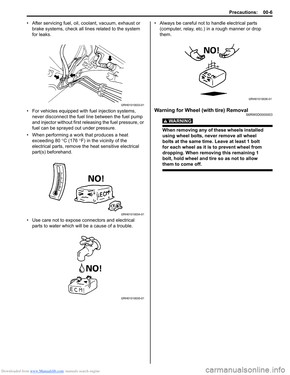
• After servicing fuel, oil, coolant, vacuum, exhaust or
brake systems, check all lines related to the system
for leaks.
• For vehicles equipped with fuel injection systems,
never disconnect the fuel line between the fuel pump
and injector without first releasing the fuel pressure, or
fuel can be sprayed out under pressure.
• When performing a work that produces a heat
exceeding 80 °C (176 °F) in the vicinity of the
electrical parts, remove the heat sensitive electrical
part(s) beforehand.
• Use care not to expose connectors and electrical
parts to water which will be a cause of a trouble.• Always be careful not to handle electrical parts
(computer, relay, etc.) in a rough manner or drop
them.
Warning for Wheel (with tire) RemovalS6RW0D0000003
WARNING!
When removing any of these wheels installed
using wheel bolts, never remove all wheel
bolts at the same time. Leave at least 1 bolt
for each wheel as it is to prevent wheel from
dropping. When removing this remaining 1
bolt, hold wheel and tire so as not to allow
them to come off.
I2RH01010033-01
I2RH01010034-01
I2RH01010035-01
I2RH01010036-01
Page 15 of 1556

Downloaded from www.Manualslib.com manuals search engine Precautions: 00-8
Precautions for Installing Mobile
Communication Equipment
S6RW0D0000005
When installing mobile communication equipment such
as CB (Citizens-Band)-radio or cellular-telephone, be
sure to observe the following precautions.
Failure to follow cautions may adversely affect electronic
control system.
• Keep the antenna as far away as possible from the
vehicle’s electronic control unit.
• Keep the antenna feeder more than 20 cm (7.9 in.)
away from electronic control unit and its wire
harnesses.
• Do not run the antenna feeder parallel with other wire
harnesses.
• Confirm that the antenna and feeder are correctly
adjusted.
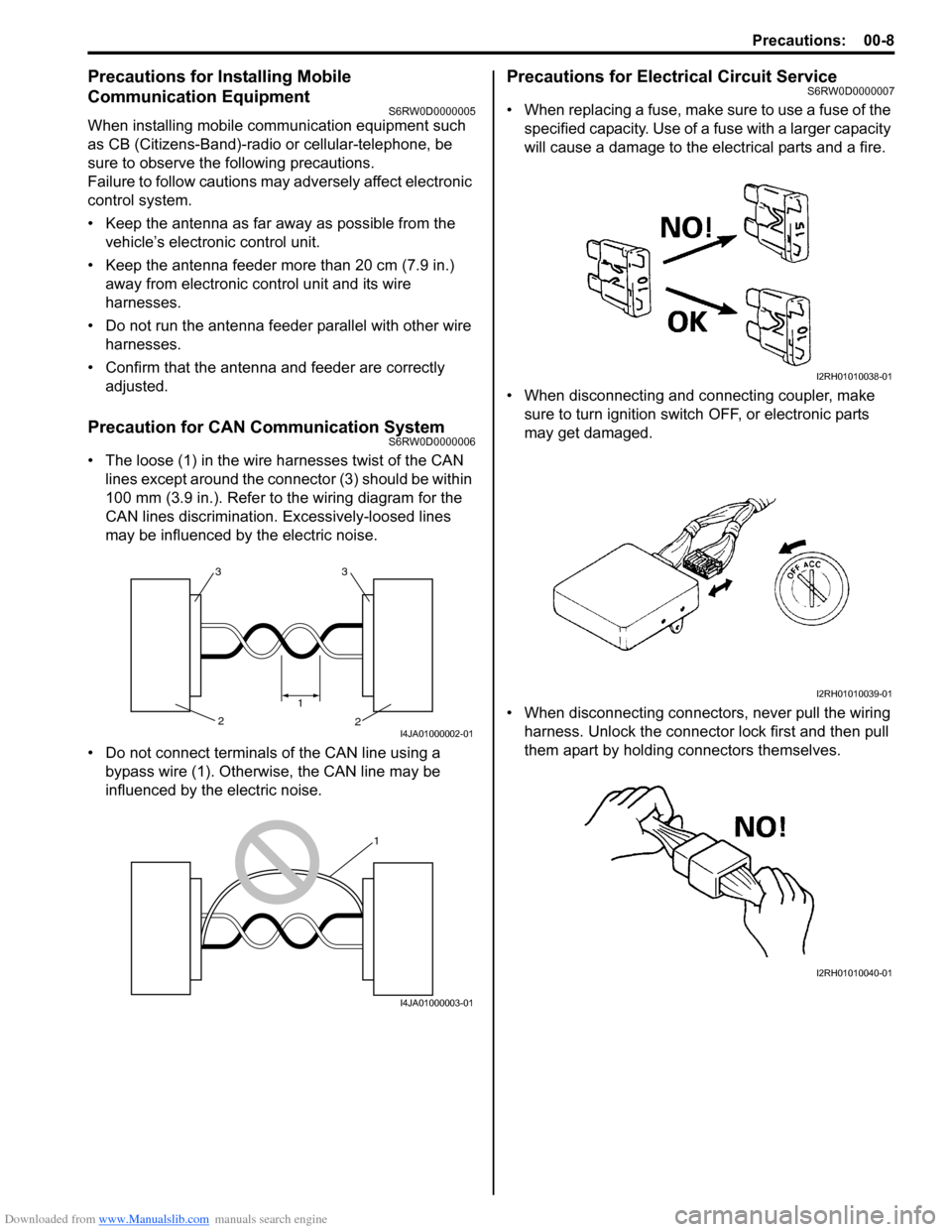
Precaution for CAN Communication SystemS6RW0D0000006
• The loose (1) in the wire harnesses twist of the CAN
lines except around the connector (3) should be within
100 mm (3.9 in.). Refer to the wiring diagram for the
CAN lines discrimination. Excessively-loosed lines
may be influenced by the electric noise.
• Do not connect terminals of the CAN line using a
bypass wire (1). Otherwise, the CAN line may be
influenced by the electric noise.
Precautions for Electrical Circuit ServiceS6RW0D0000007
• When replacing a fuse, make sure to use a fuse of the
specified capacity. Use of a fuse with a larger capacity
will cause a damage to the electrical parts and a fire.
• When disconnecting and connecting coupler, make
sure to turn ignition switch OFF, or electronic parts
may get damaged.
• When disconnecting connectors, never pull the wiring
harness. Unlock the connector lock first and then pull
them apart by holding connectors themselves.
33
2 2
1
I4JA01000002-01
1
I4JA01000003-01
I2RH01010038-01
I2RH01010039-01
I2RH01010040-01
Page 16 of 1556

Downloaded from www.Manualslib.com manuals search engine 00-9 Precautions:
• When connecting connectors, also hold connectors
and put them together until they lock securely (a click
is heard).
• When installing the wiring harness, fix it with clamps
so that no slack is left.
• When installing vehicle parts, be careful so that the
wiring harness is not interfered with or caught by any
other part.
• To avoid damage to the harness, protect its part which
may contact against a part forming a sharp angle by
winding tape or the like around it.• Be careful not to touch the electrical terminals of parts
which use microcomputers (e.g. electronic control unit
like as ECM, PCM, P/S controller, etc.). The static
electricity from your body can damage these parts.
• Never connect any tester (voltmeter, ohmmeter, or
whatever) to electronic control unit when its coupler is
disconnected. Attempt to do it may cause damage to
it.
• Never connect an ohmmeter to electronic control unit
with its coupler connected to it. Attempt to do it may
cause damage to electronic control unit and sensors.
• Be sure to use a specified voltmeter / ohmmeter.
Otherwise, accurate measurements may not be
obtained or personal injury may result. If not specified,
use a voltmeter with high impedance (M Ω/V
minimum) or a digital type voltmeter.
• When taking measurements at electrical connectors
using a tester probe, be sure to insert the probe (2)
from the wire harness side (backside) of the
connector (1).
I2RH01010041-01
I2RH01010042-01
I2RH01010043-01
I2RH01010044-01
I3RM0A000004-01
I2RH01010046-01
Page 19 of 1556

Downloaded from www.Manualslib.com manuals search engine Precautions: 00-12
Repair Instructions
Electrical Circuit Inspection ProcedureS6RW0D0006001
While there are various electrical circuit inspection
methods, described here is a general method to check
its open and short circuit by using an ohmmeter and a
voltmeter.
Open Circuit Check
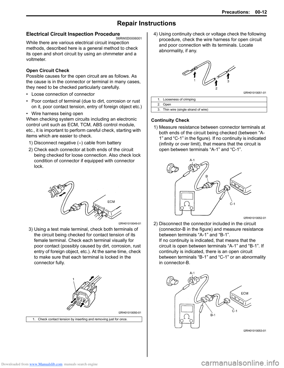
Possible causes for the open circuit are as follows. As
the cause is in the connector or terminal in many cases,
they need to be checked particularly carefully.
• Loose connection of connector
• Poor contact of terminal (due to dirt, corrosion or rust
on it, poor contact tension, entry of foreign object etc.)
• Wire harness being open
When checking system circuits including an electronic
control unit such as ECM, TCM, ABS control module,
etc., it is important to perform careful check, starting with
items which are easier to check.
1) Disconnect negative (–) cable from battery
2) Check each connector at both ends of the circuit
being checked for loose connection. Also check lock
condition of connector if equipped with connector
lock.
3) Using a test male terminal, check both terminals of
the circuit being checked for contact tension of its
female terminal. Check each terminal visually for
poor contact (possibly caused by dirt, corrosion, rust
entry of foreign object, etc.). At the same time, check
to make sure that each terminal is locked in the
connector fully.4) Using continuity check or voltage check the following
procedure, check the wire harness for open circuit
and poor connection with its terminals. Locate
abnormality, if any.
Continuity Check
1) Measure resistance between connector terminals at
both ends of the circuit being checked (between “A-
1” and “C-1” in the figure). If no continuity is indicated
(infinity or over limit), that means that the circuit is
open between terminals “A-1” and “C-1”.
2) Disconnect the connector included in the circuit
(connector-B in the figure) and measure resistance
between terminals “A-1” and “B-1”.
If no continuity is indicated, that means that the
circuit is open between terminals “A-1” and “B-1”. If
continuity is indicated, there is an open circuit
between terminals “B-1” and “C-1” or an abnormality
in connector-B.
1. Check contact tension by inserting and removing just for once.
I2RH01010049-01
I2RH01010050-01
1. Looseness of crimping
2. Open
3. Thin wire (single strand of wire)
I2RH01010051-01
I2RH01010052-01
I2RH01010053-01