2006 SUZUKI SX4 ESP
[x] Cancel search: ESPPage 509 of 1556

Downloaded from www.Manualslib.com manuals search engine Differential: 3B-12
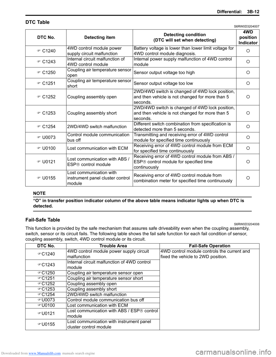
DTC TableS6RW0D3204007
NOTE
“O” in transfer position indicator column of the above table means indicator lights up when DTC is
detected.
Fail-Safe TableS6RW0D3204008
This function is provided by the safe mechanism that assures safe driveability even when the coupling assembly,
switch, sensor or its circuit fails. The following table shows the fail safe function for each fail condition of sensor,
coupling assembly, switch, 4WD control module or its circuit. DTC No. Detecting itemDetecting condition
(DTC will set when detecting)4WD
position
Indicator
�) C12404WD control module power
supply circuit malfunctionBattery voltage is lower than lower limit voltage for
4WD control module diagnosis.�{
�) C1243Internal circuit malfunction of
4WD control moduleInternal power supply malfunction of 4WD control
module�{
�) C1250Coupling air temperature sensor
openSensor output voltage too high�{
�) C1251Coupling air temperature sensor
shortSensor output voltage too low�{
�) C1252 Coupling assembly open2WD/4WD switch is changed of 4WD lock position,
and then vehicle is not changed for more than 5
seconds.�{
�) C1253 Coupling assembly short2WD/4WD switch is changed of 4WD lock position,
and then vehicle is not changed for more than 5
seconds.�{
�) C1254 2WD/4WD switch malfunctionDifferent switch combination from specification is
detected more than 5 seconds.�{
�) U0073Control module communication
bus offTransmitting and receiving error of 4WD control
module for specified time continuously�{
�) U0100 Lost communication with ECMReceiving error of 4WD control module from ECM
for specified time continuously�{
�) U0121Lost communication with ABS /
ESP® control moduleReceiving error of 4WD control module from ABS /
ESP® control module for specified time
continuously�{
�) U0155Lost communication with
instrument panel cluster control
moduleReceiving error of 4WD control module from
combination meter for specified time continuously�{
DTC No. Trouble Area Fail-Safe Operation
�)C12404WD control module power supply circuit
malfunction4WD control module controls the current and
fixed the vehicle to 2WD position.
�)C1243Internal circuit malfunction of 4WD control
module
�)C1250 Coupling air temperature sensor open
�)C1251 Coupling air temperature sensor short
�)C1252 Coupling assembly open
�)C1253 Coupling assembly short
�)C1254 2WD/4WD switch malfunction
�)U0073 Control module communication bus off
�)U0100 Lost communication with ECM
�)U0121Lost communication with ABS / ESP® control
module
�)U0155Lost communication with instrument panel
cluster control module
Page 510 of 1556

Downloaded from www.Manualslib.com manuals search engine 3B-13 Differential:
Scan Tool DataS6RW0D3204009
Scan Tool Data Definitions
Accel pedal Pos (Accelerator pedal position) (%)
Accelerator pedal opening ratio detected by signal on
CAN communication line fed from ECM.
Engine Speed (RPM)
This parameter indicates engine revolution calculated by
4WD control module.
4WD mode (2WD / AUTO / LOCK / ABS mode / Yaw
cont / ESP® req)
This parameter indicates 4WD mode according to 2WD/
4WD switch signal status detected by 4WD control
module.
4WD current (A)
This parameter indicates input current of coupling
assembly.
Battery voltage (V)
This parameter indicates battery voltage detected by
4WD control module.Coupling temp (°C, °F)
Coupling temperature detected by coupling air
temperature sensor installed in coupling assembly.
Wheel speed (F), Wheel speed (R) (km/h, mph)
Wheel speed is an ABS / ESP® control module internal
parameter. It is computed by reference pulses from the
wheel speed sensor.
F-R Wheel speed diff (Front-rear wheel speed
differential) (rpm)
This parameter indicates rotation difference between
front wheel and rear wheel detected by 4WD control
module.
4WD duty (%)
This parameter indicates operation rate of coupling
assembly. Scan tool data Vehicle conditionNormal condition / reference
values
�) Accel pedal PosIgnition switch ON after
warmed up engineAccelerator pedal released 0 – 5%
Accelerator pedal depressed
fully90 – 100%
�) Engine speed At engine idle speed Engine idle speed is display
�) 4WD mode2WD/4WD switch selected to 2WD position 2WD
2WD/4WD switch selected to AUTO position AUTO
2WD/4WD switch selected to LOCK position LOCK
ABS operating ABS mode
Ignition switch ON and engine stop Relay off
Stability control operating Yaw cont
ESP® operating ESP® mode
�) 4WD current Engine running 0 – 200 mA
�) Battery voltage At engine idle speed 10 – 14 V
�) Coupling temp Engine running –40 °C – 100 °C (–40 °F – 212 °F)
�) Wheel speed (F) Vehicle stop 0 km/h, 0 MPH
�) Wheel speed (R) Vehicle stop 0 km/h, 0 MPH
�) F-R Wheel speed
DiffVehicle stop 0 rpm
�) 4WD dutyIgnition switch ON and 2WD/4WD switch selected to
2WD position0%
Page 511 of 1556

Downloaded from www.Manualslib.com manuals search engine Differential: 3B-14
Rear Differential Symptom DiagnosisS6RW0D3204011
4WD Control Symptom DiagnosisS6RW0D3204012
Diagnose 4WD system after performing the following inspections.
• Perform 4WD control system check referring to “4WD Control System Check”. Condition Possible cause Correction / Reference Item
Gear noiseDeteriorated or water mixed lubricantRepair and replenish referring to “Rear
Differential Oil Change”.
Inadequate or insufficient lubricantRepair and replenish referring to “Rear
Differential Oil Change”.
Maladjusted backlash between drive
bevel pinion and gearAdjust as prescribed referring to “Rear
Differential Disassembly and Reassembly”.
Improper tooth contact in the mesh
between drive bevel pinion and gearAdjust or replace referring to “Rear Differential
Disassembly and Reassembly”.
Loose drive bevel gear securing boltsReplace or retighten referring to “Rear
Differential Disassembly and Reassembly”.
Damaged differential gear(s) or
differential pinion(s)Replace referring to “Rear Differential
Inspection”.
Bearing noise(Constant noise) Deteriorated or water
mixed lubricantRepair and replenish referring to “Rear
Differential Oil Change”.
(Constant noise) Inadequate or
insufficient lubricantRepair and replenish referring to “Rear
Differential Oil Change”.
(Noise while coasting) Damaged
bearing(s) of drive bevel pinionReplace referring to “Rear Differential
Inspection”.
(Noise while turning) Damaged
differential side bearing(s) or axle
bearing(s)Replace referring to “Rear Differential
Inspection”.
Oil leakageClogged breather plugClean.
Worn or damaged oil sealReplace.
Excessive oilAdjust oil level referring to “Rear Differential Oil
Change”.
Loose differential carrier boltsReplace or retighten.
Condition Possible cause Correction / Reference Item
4WD system does not
operate2WD/4WD switch faultyCheck switch referring to “2WD/4WD Switch
Inspection”.
Coupling air temperature sensor faultyCheck coupling air temperature sensor
referring to “Coupling Air Temperature Sensor
Inspection”.
Coupling assembly faultyCheck coupling assembly referring to
“Coupling Assembly Inspection”.
Wiring or grounding faultyRepair as necessary.
4WD control module faultyCheck 4WD control module referring to
“Inspection of 4WD Control Module and Its
Circuits”.
MAF sensor faultyCheck MAF sensor and its circuit.
Accelerator pedal position (APP) sensor
faultyCheck accelerator pedal position (APP) sensor
and its circuit.
CKP sensor faultyCheck CKP sensor and its circuit.
Front and/or rear wheel speed sensor
faultyCheck front and/or rear wheel speed sensor
and its circuit.
Steering angle sensor faultyCheck steering angle sensor and its circuit.
ABS / ESP® control module faultyCheck ABS / ESP
® control module and its
circuit.
ECM faultyCheck ECM and its circuit.
NoiseDamaged or worn bearing(s)Refer to “Rear Differential Inspection”.
Page 524 of 1556

Downloaded from www.Manualslib.com manuals search engine 3B-27 Differential:
DTC U0073: Control Module Communication Bus OffS6RW0D3204022
Refer to “Troubleshooting for CAN-DTC in Section 1A”.
DTC U0100: Lost Communication with ECMS6RW0D3204023
Refer to “Troubleshooting for CAN-DTC in Section 1A”.
DTC U0121: Lost Communication with ABS / ESP® Control ModuleS6RW0D3204024
Refer to “Troubleshooting for CAN-DTC in Section 1A”.
DTC U0155: Lost Communication with Instrument Panel Cluster (IPC) Control ModuleS6RW0D3204025
Refer to “Troubleshooting for CAN-DTC in Section 1A”.
Inspection of 4WD Control Module and Its CircuitsS6RW0D3204026
4WD control module and its circuits can be checked at coupler connected to 4WD control module by measuring
voltage, pulse signal.
CAUTION!
4WD control module cannot be checked by itself. It is strictly prohibited to connect voltmeter or
ohmmeter to 4WD control module with couplers disconnected from it.
Voltage and Signal Check
1) Check voltage using voltmeter (1) connected to each terminal of couplers.
2) Check signal using oscilloscope (2) connected to each terminal of couplers.
NOTE
• As each terminal voltage is affected by the battery voltage, confirm that it is 11 V or more when
ignition switch is turned ON.
• Pulse signal cannot be measured by voltmeter. It can be measured by oscilloscope.
• Item with asterisk (*) in normal voltage column can be read only by oscilloscope.
12
I4JA01332053-01
Page 603 of 1556

Downloaded from www.Manualslib.com manuals search engine Parking Brake: 4D-2
Repair Instructions
Parking Brake Inspection and AdjustmentS6RW0D4406001
Inspection
Hold center of parking brake lever grip and pull it up with
200 N (20 kg, 44 lbs) force.
With parking brake lever pulled up as shown, count
ratchet notches. There should be 4 – 9 notches.
Also, check if both right and left rear wheels are locked
firmly.
To count number of notches easily, listen to click sounds
that ratchet makes while pulling parking brake lever
without pressing its button.
One click sound corresponds to one notch.
If number of notches is out of specification, adjust cable
referring to adjustment procedure so as to obtain
specified parking brake stroke.
NOTE
Check tooth tip of each notch for damage or
wear.
If any damage or wear is found, replace
parking brake lever.
Adjustment
NOTE
Make sure for the following conditions before
cable adjustment.
• No air is trapped in brake system.
• Brake pedal travel is proper.
• Start engine and then brake pedal has
been depressed at least 3 times with about
300 N (30 kg, 66 lbs) load.
• Parking brake lever has been pulled up a
few times with about 200 N (20 kg, 44 lbs)
load.
If parking brake cable is replaced with new
one, pull up parking brake lever a few
times with about 500 N⋅m (50 kg, 110 lbs)
force.
After confirming that the conditions are all satisfied,
adjust parking brake lever stroke by loosening or
tightening adjust nut (1).
NOTE
Check brake drum for dragging after
adjustment.
Parking brake stroke
When lever is pulled up at 200 N (20 kg, 44 lbs): 4 to
9 notches
Parking Brake Cable Removal and InstallationS6RW0D4406002
Removal
NOTE
When it is necessary to remove both right
and left parking brake cables, repeat below
steps 2) and 6) on right and left wheels.
1) Hoist vehicle.
2) Remove wheel.
3) Disconnect parking brake cable from equalizer
(parking brake lever) and clamps.
4) Remove brake drum. Refer to “Rear Brake Drum
Removal and Installation in Section 4C”.
5) Disconnect parking brake cable from brake shoe
lever referring to “Rear Brake Shoe Removal and
Installation in Section 4C”.
6) Remove parking brake cable and parking cable
bracket.
Installation
Install it by reversing removal procedure, noting the
following points.
• Install clamps properly referring to “Parking Brake
Cable Construction”.
• Tighten bolts and nuts to specified torque referring to
“Parking Brake Cable Construction”.
• Adjust parking brake cable. Refer to “Parking Brake
Inspection and Adjustment”.
• Check brake drum for dragging and brake system for
proper performance. Brake test should be performed.
I4RS0B440002-01
1
I6RW0C440002-01
Page 637 of 1556

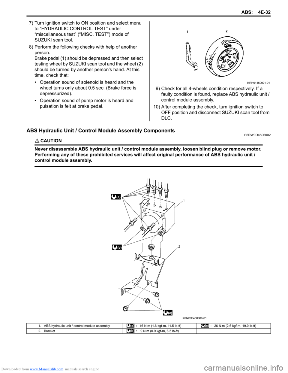
Downloaded from www.Manualslib.com manuals search engine ABS: 4E-32
7) Turn ignition switch to ON position and select menu
to “HYDRAULIC CONTROL TEST” under
“miscellaneous test” (“MISC. TEST”) mode of
SUZUKI scan tool.
8) Perform the following checks with help of another
person.
Brake pedal (1) should be depressed and then select
testing wheel by SUZUKI scan tool and the wheel (2)
should be turned by another person’s hand. At this
time, check that:
• Operation sound of solenoid is heard and the
wheel turns only about 0.5 sec. (Brake force is
depressurized).
• Operation sound of pump motor is heard and
pulsation is felt at brake pedal.9) Check for all 4-wheels condition respectively. If a
faulty condition is found, replace ABS hydraulic unit /
control module assembly.
10) After completing the check, turn ignition switch to
OFF position and disconnect SUZUKI scan tool from
DLC.
ABS Hydraulic Unit / Control Module Assembly ComponentsS6RW0D4506002
CAUTION!
Never disassemble ABS hydraulic unit / control module assembly, loosen blind plug or remove motor.
Performing any of these prohibited services will affect original performance of ABS hydraulic unit /
control module assembly.
I4RH01450021-01
I6RW0C450006-01
1. ABS hydraulic unit / control module assembly : 16 N⋅m (1.6 kgf-m, 11.5 lb-ft) : 26 N⋅m (2.6 kgf-m, 19.0 lb-ft)
2. Bracket : 9 N⋅m (0.9 kgf-m, 6.5 lb-ft)
Page 680 of 1556

Downloaded from www.Manualslib.com manuals search engine 5A-32 Automatic Transmission/Transaxle:
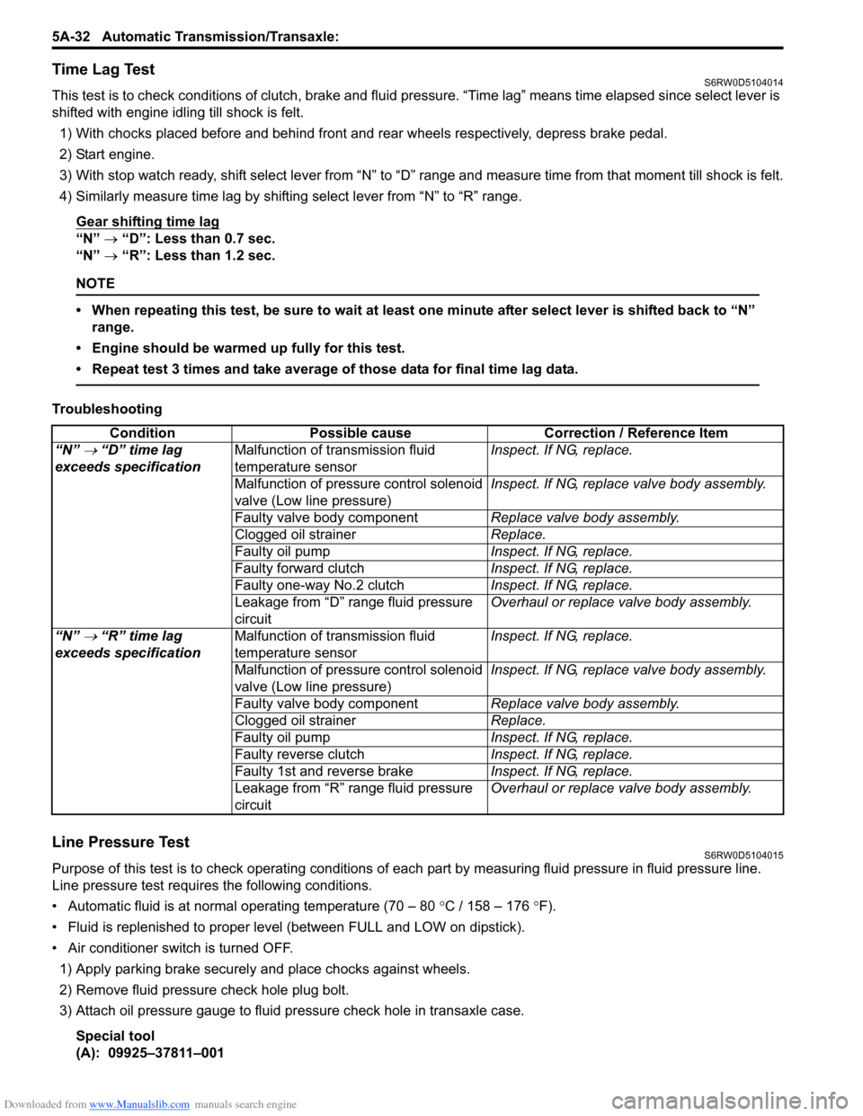
Time Lag TestS6RW0D5104014
This test is to check conditions of clutch, brake and fluid pressure. “Time lag” means time elapsed since select lever is
shifted with engine idling till shock is felt.
1) With chocks placed before and behind front and rear wheels respectively, depress brake pedal.
2) Start engine.
3) With stop watch ready, shift select lever from “N” to “D” range and measure time from that moment till shock is felt.
4) Similarly measure time lag by shifting select lever from “N” to “R” range.
Gear shifting time lag
“N” → “D”: Less than 0.7 sec.
“N” → “R”: Less than 1.2 sec.
NOTE
• When repeating this test, be sure to wait at least one minute after select lever is shifted back to “N”
range.
• Engine should be warmed up fully for this test.
• Repeat test 3 times and take average of those data for final time lag data.
Troubleshooting
Line Pressure TestS6RW0D5104015
Purpose of this test is to check operating conditions of each part by measuring fluid pressure in fluid pressure line.
Line pressure test requires the following conditions.
• Automatic fluid is at normal operating temperature (70 – 80 °C / 158 – 176 °F).
• Fluid is replenished to proper level (between FULL and LOW on dipstick).
• Air conditioner switch is turned OFF.
1) Apply parking brake securely and place chocks against wheels.
2) Remove fluid pressure check hole plug bolt.
3) Attach oil pressure gauge to fluid pressure check hole in transaxle case.
Special tool
(A): 09925–37811–001Condition Possible cause Correction / Reference Item
“N”
→ “D” time lag
exceeds specificationMalfunction of transmission fluid
temperature sensorInspect. If NG, replace.
Malfunction of pressure control solenoid
valve (Low line pressure)Inspect. If NG, replace valve body assembly.
Faulty valve body componentReplace valve body assembly.
Clogged oil strainerReplace.
Faulty oil pumpInspect. If NG, replace.
Faulty forward clutchInspect. If NG, replace.
Faulty one-way No.2 clutchInspect. If NG, replace.
Leakage from “D” range fluid pressure
circuitOverhaul or replace valve body assembly.
“N”
→ “R” time lag
exceeds specificationMalfunction of transmission fluid
temperature sensorInspect. If NG, replace.
Malfunction of pressure control solenoid
valve (Low line pressure)Inspect. If NG, replace valve body assembly.
Faulty valve body componentReplace valve body assembly.
Clogged oil strainerReplace.
Faulty oil pumpInspect. If NG, replace.
Faulty reverse clutchInspect. If NG, replace.
Faulty 1st and reverse brakeInspect. If NG, replace.
Leakage from “R” range fluid pressure
circuitOverhaul or replace valve body assembly.
Page 691 of 1556

Downloaded from www.Manualslib.com manuals search engine Automatic Transmission/Transaxle: 5A-43
DTC Detecting Condition and Trouble Area
DTC Confirmation Procedure
1) Connect scan tool to DLC with ignition switch OFF.
2) Clear DTCs in TCM memory by using scan tool.
3) Start engine and shift select lever to “D” range.
4) Keep engine running at idle speed for 25 seconds or more.
5) Stop vehicle and check DTC.
DTC TroubleshootingDTC detecting condition Trouble area
Multiple or more signals are inputted simultaneously for 10
seconds.• Select cable maladjusted
• Transmission range sensor maladjusted
• Transmission range sensor or its circuit malfunction
•TCM
Step Action Yes No
1Was “A/T System Check” performed?Go to Step 2. Go to “A/T System
Check”.
2Do you have SUZUKI scan tool?Go to Step 3. Go to Step 4.
3Check transmission range sensor circuit for operation
Check by using SUZUKI scan tool:
1) Connect SUZUKI scan tool to DLC with ignition switch
OFF.
2) Turn ignition switch ON and check transmission range
signal (“P”, “R”, “N”, “D”, “2” or “L”) on display when
shifting select lever to each range.
Is applicable range indicated?Intermittent trouble.
Check for intermittent
referring to “Intermittent
and Poor Connection
Inspection in Section
00”.Go to Step 5.
4Check transmission range sensor circuit for operation
Check by not using SUZUKI scan tool:
1) Turn ignition switch ON.
2) Check voltage at terminals “C07-1”, “C07-7”, “C07-8”,
“C07-18”, “C07-19” and “C07-20” respectively with
select lever shifted to each range.
Taking terminal “C07-19” as an example, is battery
voltage indicated only when select lever is shifted to “2”
range and 0 V for other ranges as shown in the following
table.
Check voltage at other terminals likewise, referring to the
following table.
Are check results satisfactory?Intermittent trouble.
Check for intermittent
referring to “Intermittent
and Poor Connection
Inspection in Section
00”.Go to Step 5.
5 1) Check select cable for adjustment referring to “Select
Cable Adjustment”.
Is it adjusted correctly?Go to Step 6. Adjust.
6Check transmission range sensor for installation
position
1) Shift select lever to “N” range.
2) Check that “N” reference line on sensor and needle
direction shaped on lock washer are aligned.
Are they aligned?Go to Step 7. Adjust.