Page 1509 of 1556

Downloaded from www.Manualslib.com manuals search engine Immobilizer Control System: 10C-7
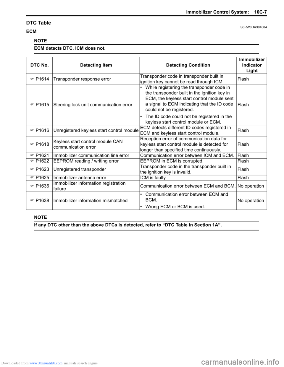
DTC TableS6RW0DA304004
ECM
NOTE
ECM detects DTC. ICM does not.
NOTE
If any DTC other than the above DTCs is detected, refer to “DTC Table in Section 1A”.
DTC No. Detecting Item Detecting ConditionImmobilizer
Indicator
Light
�) P1614 Transponder response errorTransponder code in transponder built in
ignition key cannot be read through ICM.Flash
�) P1615 Steering lock unit communication error• While registering the transponder code in
the transponder built in the ignition key in
ECM, the keyless start control module sent
a signal to ECM indicating that the ID code
could not be registered.
• The ID code could not be registered in the
keyless start control module or ECM.Flash
�) P1616 Unregistered keyless start control moduleECM detects different ID codes registered in
ECM and keyless start control module.Flash
�) P1618Keyless start control module CAN
communication errorReception error of communication data for
keyless start control module is detected for
longer than specified time continuously.Flash
�) P1621 Immobilizer communication line error Communication error between ICM and ECM. Flash
�) P1622 EEPROM reading / writing error EEPROM in ECM is corrupted. Flash
�) P1623 Unregistered transponderTransponder code in the transponder built in
the ignition key is invalid.Flash
�) P1625 Immobilizer antenna error ICM is faulty. Flash
�) P1636Immobilizer information registration
failureCommunication error between ECM and BCM. No operation
�) P1638 Immobilizer information mismatched• Communication error between ECM and
BCM.
• Wrong ECM or BCM is used.No operation
Page 1512 of 1556

Downloaded from www.Manualslib.com manuals search engine 10C-10 Immobilizer Control System:
Immobilizer Indicator Light Remains ON after Engine StartS6RW0DA304007
Wiring Diagram
Refer to “Immobilizer Control System Wiring Circuit Diagram”.
Circuit Description
Refer to “Immobilizer Indicator Light Does Not Come ON with Ignition Switch ON and Engine Stop”.
Troubleshooting
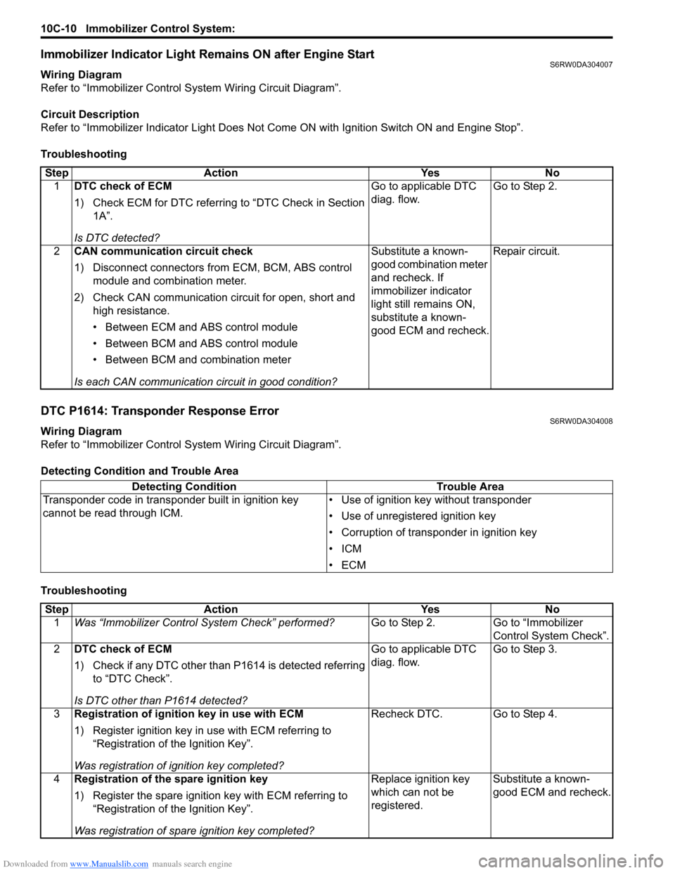
DTC P1614: Transponder Response ErrorS6RW0DA304008
Wiring Diagram
Refer to “Immobilizer Control System Wiring Circuit Diagram”.
Detecting Condition and Trouble Area
TroubleshootingStep Action Yes No
1DTC check of ECM
1) Check ECM for DTC referring to “DTC Check in Section
1A”.
Is DTC detected?Go to applicable DTC
diag. flow.Go to Step 2.
2CAN communication circuit check
1) Disconnect connectors from ECM, BCM, ABS control
module and combination meter.
2) Check CAN communication circuit for open, short and
high resistance.
• Between ECM and ABS control module
• Between BCM and ABS control module
• Between BCM and combination meter
Is each CAN communication circuit in good condition?Substitute a known-
good combination meter
and recheck. If
immobilizer indicator
light still remains ON,
substitute a known-
good ECM and recheck.Repair circuit.
Detecting Condition Trouble Area
Transponder code in transponder built in ignition key
cannot be read through ICM.• Use of ignition key without transponder
• Use of unregistered ignition key
• Corruption of transponder in ignition key
•ICM
•ECM
Step Action Yes No
1Was “Immobilizer Control System Check” performed?Go to Step 2. Go to “Immobilizer
Control System Check”.
2DTC check of ECM
1) Check if any DTC other than P1614 is detected referring
to “DTC Check”.
Is DTC other than P1614 detected?Go to applicable DTC
diag. flow.Go to Step 3.
3Registration of ignition key in use with ECM
1) Register ignition key in use with ECM referring to
“Registration of the Ignition Key”.
Was registration of ignition key completed?Recheck DTC. Go to Step 4.
4Registration of the spare ignition key
1) Register the spare ignition key with ECM referring to
“Registration of the Ignition Key”.
Was registration of spare ignition key completed?Replace ignition key
which can not be
registered.Substitute a known-
good ECM and recheck.
Page 1536 of 1556

Downloaded from www.Manualslib.com manuals search engine 10E-14 Keyless Start System:
Keyless Start System Operation InspectionS6RW0DA504011
Keyless Engine Start Operation
1) Sit in driver seat with remote controller carried with
you.
2) Check that all doors are closed and ignition key is
not inserted in ignition key cylinder.
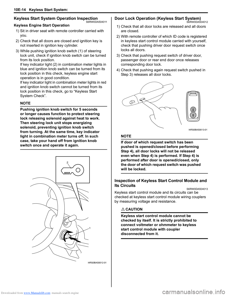
3) While pushing ignition knob switch (1) of steering
lock unit, check if ignition knob switch can be turned
from its lock position.
If key indicator light (2) in combination meter lights in
blue and ignition knob switch can be turned from its
lock position in this check, keyless engine start
operation is in good condition.
If key indicator light in combination meter lights in red
and ignition knob switch cannot be turned from its
lock position in this check, go to “Keyless Start
System Check”.
NOTE
Pushing ignition knob switch for 5 seconds
or longer causes function to protect steering
lock releasing solenoid against heat to work.
Then steering lock unit stops energizing
solenoid, preventing ignition knob switch
from turning. At the same time, key indicator
light in combination meter turns off. In such
case, take your hand off from ignition knob
switch once and operate it again.
Door Lock Operation (Keyless Start System)S6RW0DA504012
1) Check that all door locks are released and all doors
are closed.
2) With remote controller of which ID code is registered
in keyless start control module carried with yourself,
check that pushing driver door request switch once
locks all doors.
3) Check that pushing request switch of driver door,
passenger door or rear end door once releases
corresponding door lock.
4) Check that pushing again request switch pushed in
Step 3) releases all door locks.
NOTE
If door of which request switch has been
pushed is opened/closed before performing
Step 4), all door locks will not be released
even when Step 4) is performed. If Step 4) is
performed after door is opened/closed, only
the door of which request switch was pushed
will be locked.
Inspection of Keyless Start Control Module and
Its Circuits
S6RW0DA504013
Keyless start control module and its circuits can be
checked at keyless start control module wiring couplers
by measuring voltage and resistance.
CAUTION!
Keyless start control module cannot be
checked by itself. It is strictly prohibited to
connect voltmeter or ohmmeter to keyless
start control module with coupler
disconnected from it.
1 2
I4RS0BA50012-01
I4RS0BA50013-01