2006 SUZUKI SX4 generator control system description
[x] Cancel search: generator control system descriptionPage 24 of 1556

Downloaded from www.Manualslib.com manuals search engine 0A-1 General Information:
General Information
General Information
General Description
AbbreviationsS6RW0D0101001
A:
ABDC: After Bottom Dead Center
ABS: Anti-lock Brake System
AC: Alternating Current
A/C: Air Conditioning
A-ELR: Automatic-Emergency Locking Retractor
A/F: Air Fuel Mixture Ratio
ALR: Automatic Locking Retractor
API: American Petroleum Institute
APP sensor: Accelerator Pedal Position Sensor
A/T: Automatic Transmission, Automatic Transaxle
AT D C : After Top Dead Center
ATF: Automatic Transmission Fluid, Automatic
Transaxle Fluid
B:
B+: Battery Positive Voltage
BBDC: Before Bottom Dead Center
BCM: Body Electrical Control Module
BTDC: Before Top Dead Center
C:
CAN: Controller Area Network
CKT: Circuit
CKP Sensor: Crankshaft Position Sensor
CMP Sensor: Camshaft Position Sensor
CO: Carbon Monoxide
CPP Switch: Clutch Pedal Position Switch (Clutch
Switch, Clutch Start Switch)
CPU: Central Processing Unit
CRS: Child Restraint System
D:
DC: Direct Current
DLC: Data Link Connector (Assembly Line Diag. Link,
ALDL, Serial Data Link, SDL)
DOHC: Double Over Head Camshaft
DOJ: Double Offset Joint
DRL: Daytime Running Light
DTC: Diagnostic Trouble Code (Diagnostic Code)
E:
EBCM: Electronic Brake Control Module, ABS Control
Module
EBD: Electronic Brake Force Distribution
ECM: Engine Control Module
ECT Sensor: Engine Coolant Temperature Sensor
(Water Temp. Sensor, WTS)
EFE Heater: Early Fuel Evaporation Heater (Positive
Temperature Coefficient, PTC Heater)
EGR: Exhaust Gas Recirculation
EGRT Sensor: EGR Temperature Sensor (Recirculated
Exhaust Gas Temp. Sensor, REGTS)
EPS: Electronic Power Steering
EVAP: Evaporative Emission
EVAP Canister: Evaporative Emission Canister
(Charcoal Canister)F:
4WD: 4 Wheel Drive
G:
GEN: Generator
GND: Ground
GPS: Global Positioning System
H:
HAVC: Heating, Ventilating and Air Conditioning
HC: Hydrocarbons
HO2S: Heated Oxygen Sensor
I:
IAC Valve: Idle Air Control Valve (Idle Speed Control
Solenoid Valve, ISC Solenoid Valve)
IAT Sensor: Intake Air Temperature Sensor (Air
temperature Sensor, ATS)
ICM: Immobilizer Control Module
IG: Ignition
ISC Actuator: Idle Speed Control Actuator
L:
LH: Left Hand
LHD: Left Hand Drive vehicle
LSPV: Load Sensing Proportioning Valve
M:
MAF Sensor: Mass Air Flow Sensor (Air Flow Sensor,
AFS, Air Flow Meter, AFM)
MAP Sensor: Manifold Absolute Pressure Sensor
(Pressure Sensor, PS)
Max: Maximum
MFI: Multiport Fuel Injection (Multipoint Fuel Injection)
Min: Minimum
MIL: Malfunction Indicator Lamp (“SERVICE ENGINE
SOON” Light)
M/T: Manual Transmission, Manual Transaxle
N:
NOx: Nitrogen Oxides
O:
OBD: On-Board Diagnostic System (Self-Diagnosis
Function)
O/D: Overdrive
OHC: Over Head Camshaft
O2S: Oxygen Sensor
P:
PCM: Powertrain Control Module
PCV: Positive Crankcase Ventilation
PNP: Park / Neutral Position
P/S: Power Steering
PSP Switch: Power Steering Pressure Switch (P/S
Pressure Switch)
R:
RH: Right Hand
RHD: Right Hand Drive vehicle
Page 76 of 1556

Downloaded from www.Manualslib.com manuals search engine 1A-26 Engine General Information and Diagnosis:
• The MIL is turned on when the ECM and/or
TCM detect malfunction(s). Each ECM and
TCM stores diagnostic information as the
diagnostic trouble code (DTC) in its
memory and outputs the DTC to the scan
tool.
Therefore, check both of the ECM and TCM
for any DTC with the scan tool because the
DTC stored in ECM and TCM is not read
and displayed at a time. However, each of
the ECM and TCM needs not to be checked
with the generic scan tool because the
DTC stored in ECM and TCM is read and
displayed at a time.
1) Prepare CAN communication OBD generic scan tool
or SUZUKI scan tool.
Special tool
(A): SUZUKI scan tool (SUZUKI-SDT)
2) With ignition switch OFF, connect it to DLC (1)
located on underside of instrument panel at driver’s
seat side.
3) Turn ignition switch ON and confirm that MIL lights.
4) Read DTC and freeze frame data according to
instructions displayed on scan tool and print them or
write them down. Refer to scan tool operator’s
manual for details.
If communication between scan tool and ECM is not
possible, go to “Troubleshooting for Communication
Error with Scan Tool Using CAN”.
5) After completing the check, turn ignition switch off
and disconnect scan tool from DLC.
DTC ClearanceS6RW0D1104004
NOTE
There are two types of OBD system
depending on the vehicle specification.
For identification, refer to “Precaution on On-
Board Diagnostic (OBD) System”.
1) Connect SUZUKI scan tool or CAN communication
OBD generic scan tool to data link connector in the
same manner as when making this connection for
DTC check.2) Turn ignition switch OFF and then ON.
3) Erase DTC and pending DTC according to
instructions displayed on scan tool. Freeze frame
data is cleared with the DTC. Refer to scan tool
operator’s manual for further details.
If communication between scan tool and ECM is not
possible, go to “Troubleshooting for Communication
Error with Scan Tool Using CAN”.
4) After completing the clearance, turn ignition switch
OFF and disconnect scan tool from data link
connector.
NOTE
DTC and freeze frame data stored in ECM
memory are also cleared in the following
cases. Be careful not to clear them before
keeping their record.
• When power to ECM is cut off (by
disconnecting battery cable, removing
fuse or disconnecting ECM connectors).
• When the same malfunction (DTC) is not
detected again during 40 engine warm-up
cycles. (See “Warm-Up Cycle” of “On-
Board Diagnostic System Description”.)
Troubleshooting for Communication Error with
Scan Tool Using CAN
S6RW0D1104083
Perform this troubleshooting when it is not possible to
communicate between scan tool and ECM/TCM.
NOTE
• When performing this troubleshooting, be
sure to have full understanding of
“Precaution on CAN Troubleshooting” and
observe it.
• It may be possible that CAN system has
trouble because of fuse blown or low
battery voltage. Before troubleshooting,
check to make sure that fuse, battery
voltage and generator status are normal.
• When disconnecting each control module
connector in this troubleshooting, various
DTCs will be detected. Be sure to clear
DTCs in the following control modules
after completing this troubleshooting.
–ECM
–BCM
–TCM
– Keyless start control module
– 4WD control module
– HVAC control module (Auto A/C model)
– P/S control module
(A) 1I5RW0C110011-01
Page 167 of 1556

Downloaded from www.Manualslib.com manuals search engine Engine General Information and Diagnosis: 1A-117
System Description
The CMP sensor located on the transmission side of cylinder head (VVT model) or timing chain cover (non-VVT
model) consists of the signal generator (magnetic sensor) and signal rotor (intake camshaft portion (VVT model) or
exhaust camshaft timing sprocket (non-VVT model)).
The signal generator generates reference signal through slits in the slit plate which turns together with the camshaft.
Reference signal
The CMP sensor generates 6 pulses of signals each of which has a different waveform length while the camshaft
makes one full rotation. Refer to “Inspection of ECM and Its Circuits”.
Based on these signals, ECM judges which cylinder piston is in the compression stroke and the engine speed.
DTC Detecting Condition and Trouble Area
DTC Confirmation Procedure
1) With ignition switch turned OFF, connect scan tool.
2) Turn ON ignition switch and clear DTC using scan tool.
3) Crank engine for 5 sec.
4) Check DTC and pending DTC.
DTC Troubleshooting
NOTE
Before this troubleshooting is performed, read the precautions for DTC troubleshooting referring to
“Precautions for DTC Troubleshooting”.
DTC detecting condition Trouble area
• CMP sensor pulse is less than 20 pulses per crankshaft 8 revolutions
or
• CMP sensor pulse is more than 28 pulses per crankshaft 8
revolutions
or
• CMP sensor pulse is less than 20 pulses between BTDC 75° CA and
BTDC 5° CA with crankshaft 8 revolutions from engine start.
(1 driving cycle detection logic)• CMP sensor circuit open or short
• Signal rotor teeth damaged
• CMP sensor malfunction, foreign material
being attached or improper installation
•ECM
Step Action Yes No
1Was “Engine and Emission Control System Check”
performed?Go to Step 2. Go to “Engine and
Emission Control
System Check”.
2CMP sensor and connector for proper installation check
Is CMP sensor installed properly and connector connected
securely?Go to Step 3. Correct.
Page 417 of 1556

Downloaded from www.Manualslib.com manuals search engine Charging System: 1J-3
Generator DescriptionS6RW0D1A01002
The basic charging system is the IC integral regulator charging system. The internal components are connected
electrically as shown below.
Charging System Circuit
The generator features a solid state regulator that is mounted inside the generator. All regulator components are
enclosed into a solid mold, and this unit along with the brush holder assembly is attached to the rear housing. The
regulator voltage is being controlled by ECM under some conditions while driving. Refer to “Generator Control System
Description in Section 1A” in related manual.
The generator rotor bearings contain enough grease to eliminate the need for periodic lubrication.
Two brushes carry current through the two slip rings to the field coil mounted on the rotor, and under normal conditions
will provide long period of attention-free service.
The stator windings are assembled inside a laminated core that forms part of the generator frame.
A rectifier bridge connected to the stator windings contains diodes, and electrically changes that stator AC. voltages to
a D.C. voltage which appears at the generator output terminal.
1 26345
4
3B
7
8
9
10E FFRCIG
L
I6RW0D1A0002-01
1. Pulley 6. Field coil B: Generator output (Battery terminal) L: Lamp terminal
2. Pulley nut 7. Regulator C: Generator cut FR: Field duty monitor
3. Rotor fan 8. Brush E: Ground
4. Stator coil 9. Rear end frame F: Field coil terminal
5. Stator core 10. Drive end frame IG: Ignition terminal
B
IG
L
C
E
7
2 4
3
5
FR
610
11
12 13 1
[A]
IG1 9
14
8
I6RW0D1A0001-03
[A]: If equipped with electric load current sensor 4. Diode 8. Battery 12. Combination meter
1. Generator with regulator assembly 5. Field coil (rotor coil) 9. Electric load current sensor (if equipped) 13. CAN driver
2. I.C. regulator 6. Charge indicator light 10. ECM 14. Main fuse box
3. Stator coil 7. Main switch 11. BCM
Page 891 of 1556

Downloaded from www.Manualslib.com manuals search engine Power Assisted Steering System: 6C-11
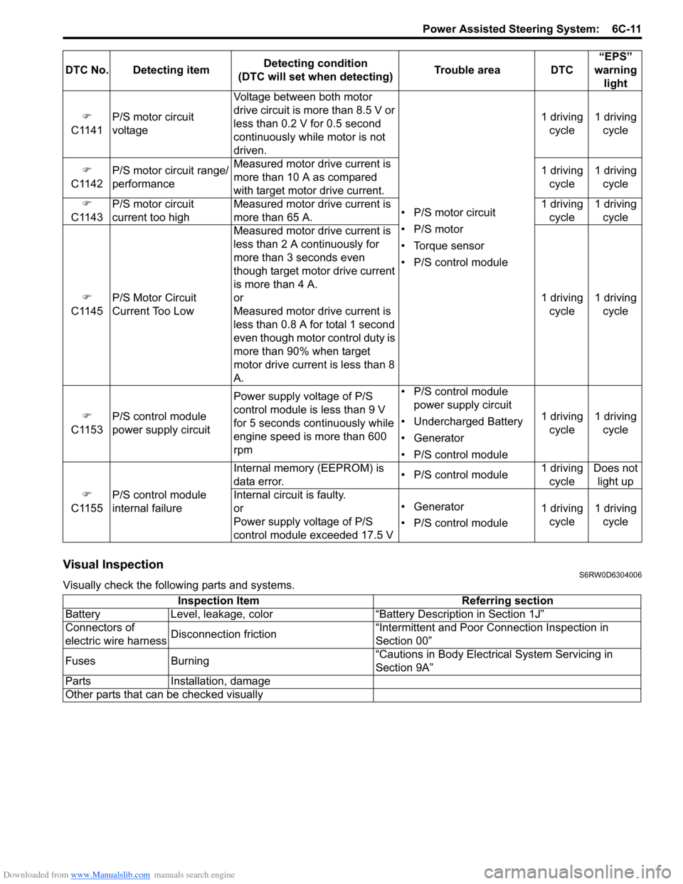
Visual InspectionS6RW0D6304006
Visually check the following parts and systems.�)
C1141P/S motor circuit
voltageVoltage between both motor
drive circuit is more than 8.5 V or
less than 0.2 V for 0.5 second
continuously while motor is not
driven.
• P/S motor circuit
• P/S motor
• Torque sensor
• P/S control module1 driving
cycle1 driving
cycle
�)
C1142P/S motor circuit range/
performanceMeasured motor drive current is
more than 10 A as compared
with target motor drive current.1 driving
cycle1 driving
cycle
�)
C1143P/S motor circuit
current too highMeasured motor drive current is
more than 65 A.1 driving
cycle1 driving
cycle
�)
C1145P/S Motor Circuit
Current Too Low Measured motor drive current is
less than 2 A continuously for
more than 3 seconds even
though target motor drive current
is more than 4 A.
or
Measured motor drive current is
less than 0.8 A for total 1 second
even though motor control duty is
more than 90% when target
motor drive current is less than 8
A.1 driving
cycle1 driving
cycle
�)
C1153P/S control module
power supply circuitPower supply voltage of P/S
control module is less than 9 V
for 5 seconds continuously while
engine speed is more than 600
rpm• P/S control module
power supply circuit
• Undercharged Battery
• Generator
• P/S control module1 driving
cycle1 driving
cycle
�)
C1155P/S control module
internal failureInternal memory (EEPROM) is
data error.• P/S control module1 driving
cycleDoes not
light up
Internal circuit is faulty.
or
Power supply voltage of P/S
control module exceeded 17.5 V• Generator
• P/S control module1 driving
cycle1 driving
cycle DTC No. Detecting itemDetecting condition
(DTC will set when detecting)Trouble area DTC“EPS”
warning
light
Inspection Item Referring section
Battery Level, leakage, color “Battery Description in Section 1J”
Connectors of
electric wire harnessDisconnection friction“Intermittent and Poor Connection Inspection in
Section 00”
Fuses Burning“Cautions in Body Electrical System Servicing in
Section 9A”
Parts Installation, damage
Other parts that can be checked visually
Page 1205 of 1556

Downloaded from www.Manualslib.com manuals search engine Wiring Systems: 9A-38
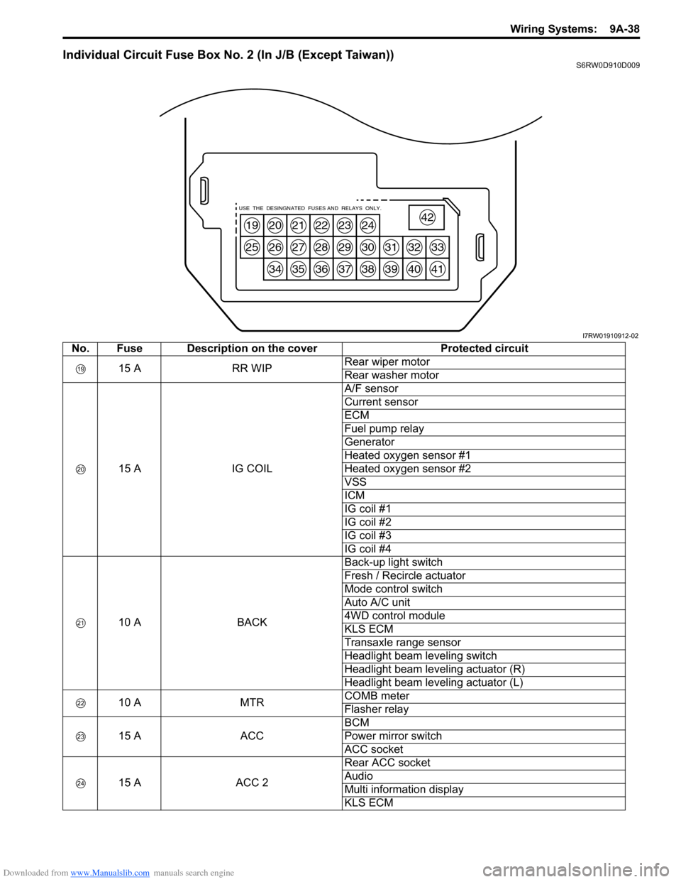
Individual Circuit Fuse Box No. 2 (In J/B (Except Taiwan))S6RW0D910D009
19
25
20
26
34
21
27
35
22
28
36
23
29
37
24
30
38
31
39
32
40
33
41
42USE THE DESINGNATED FUSES AND RELAYS ONLY.
I7RW01910912-02
No. Fuse Description on the cover Protected circuit
15 A RR WIPRear wiper motor
Rear washer motor
15 A IG COILA/F sensor
Current sensor
ECM
Fuel pump relay
Generator
Heated oxygen sensor #1
Heated oxygen sensor #2
VSS
ICM
IG coil #1
IG coil #2
IG coil #3
IG coil #4
10 A BACKBack-up light switch
Fresh / Recircle actuator
Mode control switch
Auto A/C unit
4WD control module
KLS ECM
Transaxle range sensor
Headlight beam leveling switch
Headlight beam leveling actuator (R)
Headlight beam leveling actuator (L)
10 A MTRCOMB meter
Flasher relay
15 A ACCBCM
Power mirror switch
ACC socket
15 A ACC 2Rear ACC socket
Audio
Multi information display
KLS ECM
Page 1207 of 1556

Downloaded from www.Manualslib.com manuals search engine Wiring Systems: 9A-40
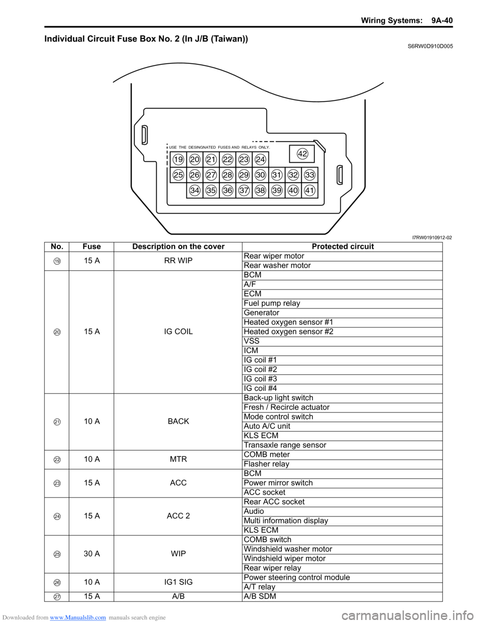
Individual Circuit Fuse Box No. 2 (In J/B (Taiwan))S6RW0D910D005
19
25
20
26
34
21
27
35
22
28
36
23
29
37
24
30
38
31
39
32
40
33
41
42USE THE DESINGNATED FUSES AND RELAYS ONLY.
I7RW01910912-02
No. Fuse Description on the cover Protected circuit
15 A RR WIPRear wiper motor
Rear washer motor
15 A IG COILBCM
A/F
ECM
Fuel pump relay
Generator
Heated oxygen sensor #1
Heated oxygen sensor #2
VSS
ICM
IG coil #1
IG coil #2
IG coil #3
IG coil #4
10 A BACKBack-up light switch
Fresh / Recircle actuator
Mode control switch
Auto A/C unit
KLS ECM
Transaxle range sensor
10 A MTRCOMB meter
Flasher relay
15 A ACCBCM
Power mirror switch
ACC socket
15 A ACC 2Rear ACC socket
Audio
Multi information display
KLS ECM
30 A WIPCOMB switch
Windshield washer motor
Windshield wiper motor
Rear wiper relay
10 A IG1 SIGPower steering control module
A/T relay
15 A A/B A/B SDM
Page 1490 of 1556

Downloaded from www.Manualslib.com manuals search engine 10B-17 Body Electrical Control System:
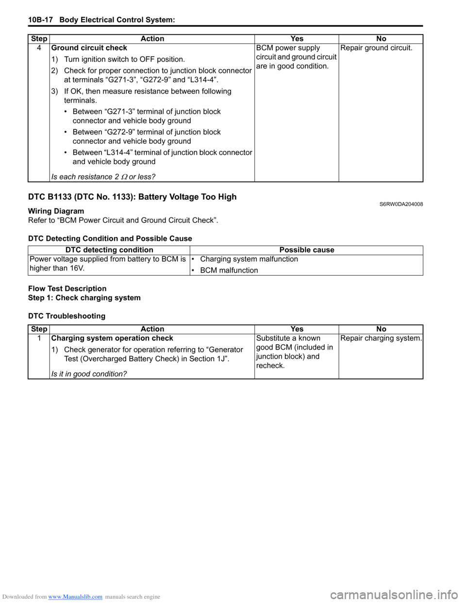
DTC B1133 (DTC No. 1133): Battery Voltage Too HighS6RW0DA204008
Wiring Diagram
Refer to “BCM Power Circuit and Ground Circuit Check”.
DTC Detecting Condition and Possible Cause
Flow Test Description
Step 1: Check charging system
DTC Troubleshooting4Ground circuit check
1) Turn ignition switch to OFF position.
2) Check for proper connection to junction block connector
at terminals “G271-3”, “G272-9” and “L314-4”.
3) If OK, then measure resistance between following
terminals.
• Between “G271-3” terminal of junction block
connector and vehicle body ground
• Between “G272-9” terminal of junction block
connector and vehicle body ground
• Between “L314-4” terminal of junction block connector
and vehicle body ground
Is each resistance 2
Ω or less?BCM power supply
circuit and ground circuit
are in good condition.Repair ground circuit. Step Action Yes No
DTC detecting condition Possible cause
Power voltage supplied from battery to BCM is
higher than 16V.• Charging system malfunction
• BCM malfunction
Step Action Yes No
1Charging system operation check
1) Check generator for operation referring to “Generator
Test (Overcharged Battery Check) in Section 1J”.
Is it in good condition?Substitute a known
good BCM (included in
junction block) and
recheck.Repair charging system.