2006 SUZUKI SX4 ESP
[x] Cancel search: ESPPage 959 of 1556

Downloaded from www.Manualslib.com manuals search engine Air Conditioning System: Manual Type 7B-19
Evacuation
CAUTION!
Do not evacuate before recovering
refrigerant in A/C system.
NOTE
Once air conditioning system circuit is
opened (exposed) to atmospheric air, system
must be evacuated by using a vacuum pump.
The A/C system should be attached with a
manifold gauge set, and should be evacuated
for approximately 15 minutes.
1) Connect high charging hose (1) and low charging
hose (2) of manifold gauge set (3) (special tool)
respectively as follows:
High charging hose → High pressure charging valve
(4) on discharge hose
Low charging hose → Low pressure charging valve
(5) on suction pipe
Special tool
(A): 09990–06020
2) Attach center charging hose (6) of manifold gauge
set to vacuum pump (7).
3) Operate vacuum pump, and then open discharge
side valve (Hi) (8) of manifold gauge set.
If there is no blockage in the system, there will be an
indication on high pressure gauge (9).
When this occurs, open the other side valve (Lo)
(10) of the set.
4) Approximately 10 minutes later, low pressure gauge
(11) should show a vacuum lower than –100 kPa (–
1.0 kgf/cm
2, –760 mmHg, –14.7 psi) providing no
leakage exists.
NOTE
• If the system does not show a vacuum
below –100 kPa (–1.0 kgf/cm
2, –760 mmHg,
–14.7 psi), close both valves, stop vacuum
pump and watch movement of low
pressure gauge.
• Increase in the gauge reading suggests
existence of leakage. In this case, repair
the system before continuing its
evacuation.
• If the gauge shows a stable reading
(suggesting no leakage), continue
evacuation.
5) Evacuation should be carried out for a total of at
least 15 minutes.
6) Continue evacuation until low pressure gauge
indicates a vacuum less than –100 kPa (–1.0 kgf/
cm
2, –760 mmHg, –14.7 psi), and then close both
valves.
7) Stop vacuum pump. Disconnect center charging
hose from pump inlet. Now, the system is ready for
charging refrigerant.
Checking A/C System for Pressure Leaks
After completing the evacuation, close manifold gauge
high pressure valve and low pressure valve and wait 10
minutes. Verify that low pressure gauge reading has not
changed.
CAUTION!
If the gauge reading moves closer to “0”,
there is a leak somewhere. Inspect the tubing
connections and make necessary
corrections. And then, evacuate system once
again and make sure that there are no leaks.
7
89 3, (A)
11
10
1
2
5
4
6
I7RW01721011-01
Page 961 of 1556

Downloaded from www.Manualslib.com manuals search engine Air Conditioning System: Manual Type 7B-21
7) When refrigerant container (1) is emptied, use the
following procedure to replace it with a new
refrigerant container.
a) Close low pressure valve.
b) Replace empty container with a refrigerant
container which has been charged with
refrigerant. When using refrigerant container tap
valve (2), use the following procedure for
replacement.
i) Retract needle (3) and remove refrigerant
container tap valve by loosening its plate nut
(4).
ii) Install the refrigerant container tap valve to a
new refrigerant container.
c) Purge any air existing in center charging hose.
When using refrigerant container tap valve, use
the following procedure to purge air.
i) Once fully tighten refrigerant container tap
valve (1), and then loosen (open) plate nut
(2) slightly.
ii) Open low pressure side valve (3) of manifold
gauge set (4) a little.
iii) As soon as refrigerant comes out with a
“hiss” through a clearance between
refrigerant container and tap valve, tighten
plate nut as well as low pressure side valve.
iv) Turn handle of tap valve clockwise so that its
needle is screwed into the new container to
make a hole for refrigerant flow.8) After the system has been charged with specified
amount of refrigerant or when low pressure gauge
(1) and high pressure gauge (2) have indicated the
following specified value, close low pressure side
valve (3) on manifold gauge set (4).
Specified amount of refrigerant
430 ± 20 g (15.2 ± 0.7 oz))
Low side and high side pressure example
Removal of Manifold Gauge Set
WARNING!
High pressure side is under high pressure.
Therefore, be careful not to get injured
especially on your eyes and skin.
For the A/C system charged with the specified amount of
refrigerant, remove manifold gauge set as follows:
1) Close low pressure side valve of manifold gauge set.
(The high pressure side valve is closed continuously
during the process of charging.)
2) Close refrigerant container valve.
3) Stop engine.
4) Using shop rag, remove charging hoses from service
valves. This operation must be performed quickly.
5) Put caps on service valves.
I2RH01720018-01
I2RH01720019-01
Gauges should read as follows when ambient
temperature is 30 °C (86 °F).
Pressure
on high pressure gauge1130 – 1560 kPa
(11.4 – 15.6 kgf/cm
2)
(162.3 – 221.8 psi)
Pressure
on low pressure gauge270 – 390 kPa
(2.7 – 3.9 kgf/cm
2)
(38.8 – 56.0 psi)
4
2
1
3
I7RW01721013-02
Page 972 of 1556

Downloaded from www.Manualslib.com manuals search engine 7B-32 Air Conditioning System: Manual Type
Compressor Assembly ComponentsS6RW0D7216021
Magnet Clutch InspectionS6RW0D7216022
• Check armature plate and magnet clutch pulley for wear and oil soak respectively.
• Check magnet clutch pulley bearing for noise, wear and grease leakage.
• Measure magnet clutch coil for resistance at 20 °C (68 °F). If the measured resistance is out of specification,
replace magnet clutch assembly.
Magnet clutch coil resistance
Standard: 3.5 – 4.0 Ω
6
2
9
4
4 3
1
7
5 8(a)
(b)
10
I7RW01721023-01
1. Armature plate bolt 5. Shim 9. O-ring
: Apply compressor oil.: Do not reuse.
2. Compressor 6. Magnet clutch coil 10. Thermal switch
3. Relief valve 7. Magnet clutch pulley : 15 N⋅m (1.5 kgf-m, 11.0 lb-ft)
4. Circlip 8. Armature plate : 8 N⋅m (0.8 kgf-m, 6.0 lb-ft)
I4RS0A720038-01
Page 979 of 1556

Downloaded from www.Manualslib.com manuals search engine Air Conditioning System: Automatic Type 7B-39
General Description
Auto A/C System DescriptionS6RW0D7221001
The automatic type air conditioning system (auto A/C) is provided with the function to automatically control the inside
air temperature, fan speed, air flow outlet direction and air intake position by HVAC control module in addition to
functions of the manual type air conditioning system (manual A/C). Once the inside air temperature is set using the
temperature selector, HVAC control module automatically controls the inside air temperature at the constant level at all
times based on the inside air temperature, outside air temperature, amount of sunlight and engine coolant
temperature detected respectively by the inside air temperature sensor, outside air temperature sensor, sunload
sensor and ECT sensor. For the electronic control system components location, refer to “Electronic Control System
Components Location”. For the A/C system components location, refer to “A/C System Major Components Location”.
Auto A/C Electronic Control Input / Output Table
Temperature selector
MODE (air flow) selector
Blower speed selector
Air intake selector
AUTO switch A/C switch
Outside air
temperature
sensor
A/C refrigerant pressure sensor
Compressor relay
Blower motor controller
Temperature control actuator
Air flow control actuator
Air intake control actuator
BCM
ECM
Data link connector
HVAC control module
CPU
ECT sensor
Sunload sensor
Inside air temperature sensor
Evaporator temperature sensor
Condenser cooling fan relay
Wheel
speed
sensor
*
*
*
Combination meterABS control module
I6RW0C722001-01
*: CAN communication
Page 990 of 1556

Downloaded from www.Manualslib.com manuals search engine 7B-50 Air Conditioning System: Automatic Type
Not Using SUZUKI Scan Tool
NOTE
In case of malfunction of temperature
selector, blower speed selector and air flow
selector, DTC can not be checked by the
following procedure. Use SUZUKI scan tool
for DTC check.
1) Light over sunload sensor vertically with an
incandescent light of approximately 100 W apart
from about 100 mm (3.94 in.).
NOTE
If sunload sensor is not lighted over with an
incandescent light, DTC of sunload sensor is
detected as current DTC even though there is
not any malfunction.
2) Set the following selectors to specified positions
below respectively with ignition switch off position.
• Temperature selector (1) is maximum cool
position
• Blower speed selector (2) is OFF position
• Air flow selector (3) is AUTO position
3) While pressing A/C switch (4) and air intake selector
(5) simultaneously, turn ignition switch to ON
position.
4) Wait for about 5 seconds (start of diagnosis).
5) Read flashing pattern of “FRE” (6) and “REC” (7)
indicator lights which represents DTC and write it
down.
NOTE
• When 2 or more current DTCs are
detected, only DTC having the highest
priority is indicated. Therefore, after
troubleshooting the malfunction, DTC
check has to be performed again to see if
any other DTC(s) is detected.
• Pressing “A/C” switch alternates display
of current DTC and history DTC. “A/C”
indicator light (8) remains off when display
is in current DTC mode and it lights up
when display is in history DTC mode.
• When a history DTC is indicated while 2 or
more history DTCs are detected, it is
possible to have other history DTC(s)
stored in HVAC control module displayed
by pressing the air intake selector.
Example: When inside air temperature sensor
circuit malfunction (Open) is set
Example: When VSS signal failure (Data error) is
set
6) After completing above check, turn ignition switch to
“OFF” position.
[A]: “REC” indicator light L: OFF
[B]: “FRE” indicator light a. About 0.5 seconds
H: ON b. About 2 seconds
[A]: “REC” indicator light a. About 0.5 seconds
[B]: “FRE” indicator light b. About 3 seconds
H: ON c. About 1.5 seconds
L: OFF
123
458
6
7I5RW0A722005-01
[A]
[B]H
L
H
L [B]
[A]
ab
aI5RW0A722006-02
[A]
[B]H
L
H
L [B]
[A]
ab
aaaa
c
I5RW0A722025-01
Page 1030 of 1556

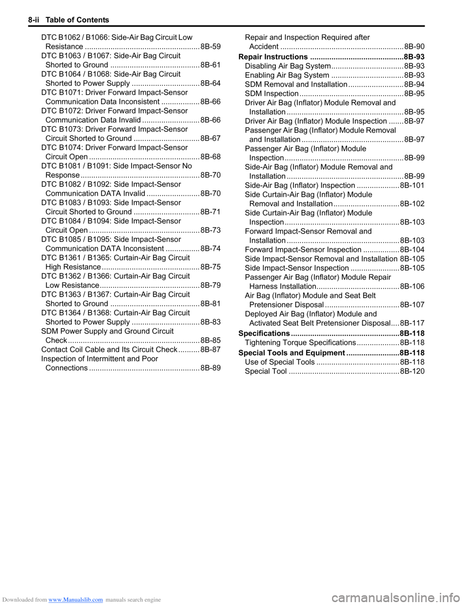
Downloaded from www.Manualslib.com manuals search engine 8-ii Table of Contents
DTC B1062 / B1066: Side-Air Bag Circuit Low
Resistance ...................................................... 8B-59
DTC B1063 / B1067: Side-Air Bag Circuit
Shorted to Ground .......................................... 8B-61
DTC B1064 / B1068: Side-Air Bag Circuit
Shorted to Power Supply ................................ 8B-64
DTC B1071: Driver Forward Impact-Sensor
Communication Data Inconsistent .................. 8B-66
DTC B1072: Driver Forward Impact-Sensor
Communication Data Invalid ........................... 8B-66
DTC B1073: Driver Forward Impact-Sensor
Circuit Shorted to Ground ............................... 8B-67
DTC B1074: Driver Forward Impact-Sensor
Circuit Open .................................................... 8B-68
DTC B1081 / B1091: Side Impact-Sensor No
Response ........................................................ 8B-70
DTC B1082 / B1092: Side Impact-Sensor
Communication DATA Invalid ......................... 8B-70
DTC B1083 / B1093: Side Impact-Sensor
Circuit Shorted to Ground ............................... 8B-71
DTC B1084 / B1094: Side Impact-Sensor
Circuit Open .................................................... 8B-73
DTC B1085 / B1095: Side Impact-Sensor
Communication DATA Inconsistent ................ 8B-74
DTC B1361 / B1365: Curtain-Air Bag Circuit
High Resistance .............................................. 8B-75
DTC B1362 / B1366: Curtain-Air Bag Circuit
Low Resistance ............................................... 8B-79
DTC B1363 / B1367: Curtain-Air Bag Circuit
Shorted to Ground .......................................... 8B-81
DTC B1364 / B1368: Curtain-Air Bag Circuit
Shorted to Power Supply ................................ 8B-83
SDM Power Supply and Ground Circuit
Check .............................................................. 8B-85
Contact Coil Cable and Its Circuit Check .......... 8B-87
Inspection of Intermittent and Poor
Connections .................................................... 8B-89Repair and Inspection Required after
Accident .......................................................... 8B-90
Repair Instructions ............................................8B-93
Disabling Air Bag System.................................. 8B-93
Enabling Air Bag System .................................. 8B-93
SDM Removal and Installation .......................... 8B-94
SDM Inspection ................................................. 8B-95
Driver Air Bag (Inflator) Module Removal and
Installation ....................................................... 8B-95
Driver Air Bag (Inflator) Module Inspection ....... 8B-97
Passenger Air Bag (Inflator) Module Removal
and Installation ................................................ 8B-97
Passenger Air Bag (Inflator) Module
Inspection ........................................................ 8B-99
Side-Air Bag (Inflator) Module Removal and
Installation ....................................................... 8B-99
Side-Air Bag (Inflator) Inspection .................... 8B-101
Side Curtain-Air Bag (Inflator) Module
Removal and Installation ............................... 8B-102
Side Curtain-Air Bag (Inflator) Module
Inspection ...................................................... 8B-103
Forward Impact-Sensor Removal and
Installation ..................................................... 8B-103
Forward Impact-Sensor Inspection ................. 8B-104
Side Impact-Sensor Removal and Installation 8B-105
Side Impact-Sensor Inspection ....................... 8B-105
Passenger Air Bag (Inflator) Module Repair
Harness Installation....................................... 8B-106
Air Bag (Inflator) Module and Seat Belt
Pretensioner Disposal ................................... 8B-107
Deployed Air Bag (Inflator) Module and
Activated Seat Belt Pretensioner Disposal.... 8B-117
Specifications ...................................................8B-118
Tightening Torque Specifications .................... 8B-118
Special Tools and Equipment .........................8B-118
Use of Special Tools ....................................... 8B-118
Special Tool .................................................... 8B-120
Page 1040 of 1556

Downloaded from www.Manualslib.com manuals search engine 8B-1 Air Bag System:
Restraint
Air Bag System
Precautions
Precautions on Service and Diagnosis of Air
Bag System
S6RW0D8200004
WARNING!
• If the air bag system and another vehicle
system both need repair, SUZUKI
recommends that the air bag system be
repaired first, to help avoid unintended air
bag system activation.
• Do not modify the steering wheel,
dashboard, both front seat or any other on
or around air bag system components.
Modifications can adversely affect air bag
system performance and lead to injury.
• Be sure to follow the procedures described
in this section. Failure to follow
procedures could result in possible air bag
system activation, personal injury or
unneeded air bag system repairs.
• WARNING / CAUTION labels are attached on each
part of air bag system components (SDM, air bag
(inflator) modules and seat belt pretensioners). Be
sure to follow the instructions.
• Many of service procedures require disconnection of
“A/B” fuse and air bag (inflator) module(s) (driver
module, passenger module, side modules and curtain
modules) from initiator circuit to avoid an accidental
deployment.
• Do not apply power to the air bag system unless all
components are connected or a diagnostic flow
requests it, as this will set a DTC.
• The “Air Bag Diagnostic System Check” must be the
starting point of any air bag diagnostics. The “Air Bag
Diagnostic System Check” will verify proper “AIR
BAG” warning light operation and will lead you to the
correct flow to diagnose any air bag malfunctions.
Bypassing these procedures may result in extended
diagnostic time, incorrect diagnosis, and incorrect
parts replacements.
• Never use air bag component parts from another
vehicle.
• If the vehicle will be exposed to temperatures over 93
°C (200 °F) (for example, during a paint baking
process), remove the air bag system components
beforehand to avoid component damage or
unintended system activation.• When handling the air bag (inflator) modules (driver
module, passenger module, side modules and curtain
modules), seat belt pretensioners (driver module and
passenger module), SDM, forward impact-sensor or
side impact-sensor be careful not to drop it or apply
an impact to it. If an excessive impact was applied
(e.g., SDM, forward impact-sensor are dropped, air
bag (inflator) module is dropped from a height of 90
cm (3 ft) or more, seat belt pretensioner (retractor
assembly) is dropped from a height of 30 cm (1 ft) or
more), never attempt disassembly or repair but
replace it with a new one.
• When using electric welding, be sure to disconnect air
bag (inflator) module connectors (driver module,
passenger module, side modules and curtain
modules) and seat belt pretensioner connectors
(driver module and passenger module) respectively.
• When applying paint around the air bag system
related parts, use care so that the harness or
connector will not be exposed to the paint mist.
• Never expose air bag system component parts
directly to hot air (drying or baking the vehicle after
painting) or flames.
WARNING!
When performing service on or around air
bag system components or air bag wiring,
follow the procedures listed in “Disabling Air
Bag System” to temporarily disable the air
bag system.
Failure to follow procedures could result in
possible air bag system activation, personal
injury or unneeded air bag system repairs.
Precautions on Handling and Storage of Air Bag
System Components
S6RW0D8200002
SDM
WARNING!
Never power up air bag system when SDM is
not rigidly attached to the vehicle. Otherwise,
personal injury may result.
CAUTION!
After detecting one time of such collision as
to meet deployment conditions, SDM must
not be used. Refer to “Air Bag Diagnostic
System Check” when checking SDM.
Page 1046 of 1556

Downloaded from www.Manualslib.com manuals search engine 8B-7 Air Bag System:
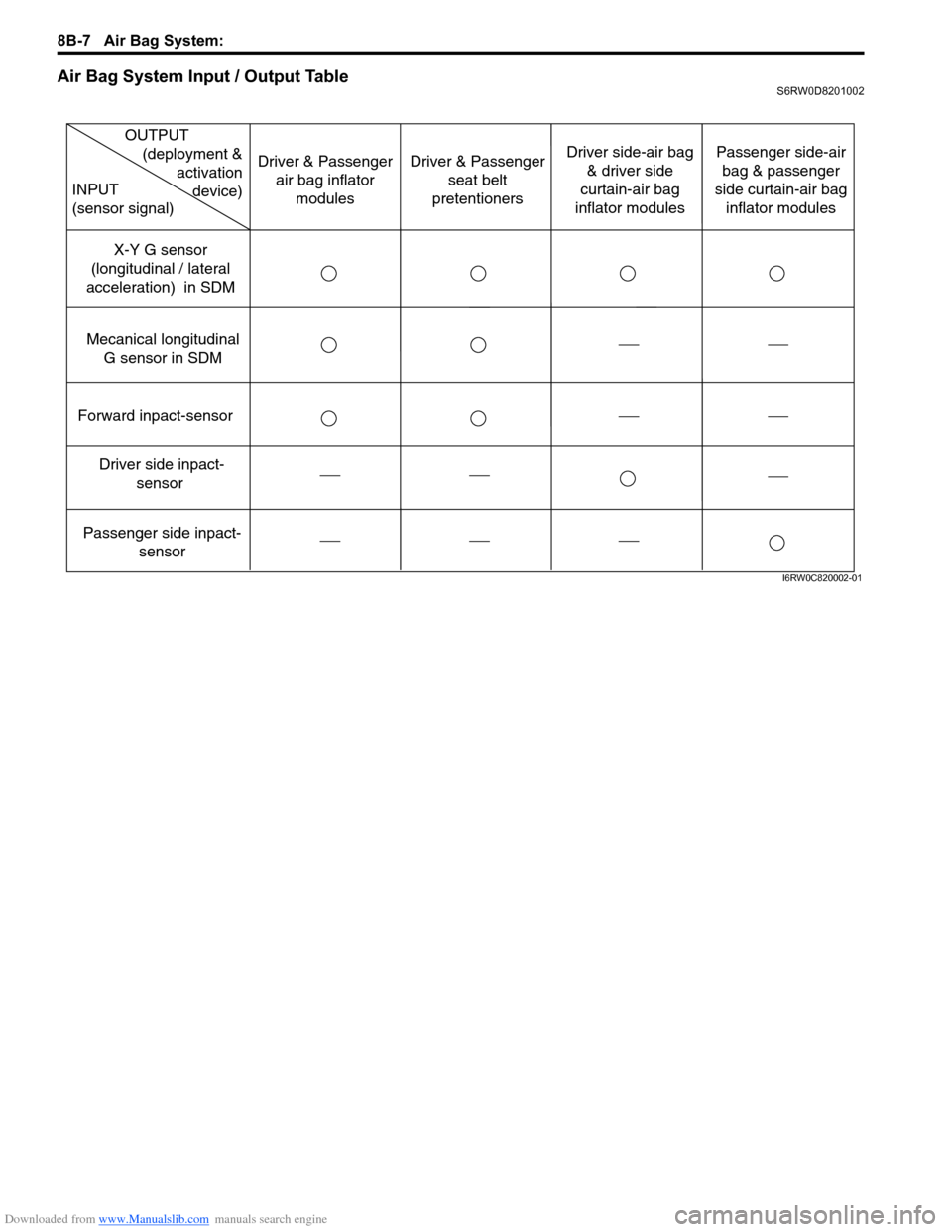
Air Bag System Input / Output TableS6RW0D8201002
Forward inpact-sensor
Driver side inpact-
sensor
Passenger side inpact-
sensor Mecanical longitudinal
G sensor in SDMX-Y G sensor
(longitudinal / lateral
acceleration) in SDM
OUTPUT
(deployment &
activation
device) INPUT
(sensor signal)
Driver & Passenger
air bag inflator
modulesDriver & Passenger
seat belt
pretentionersDriver side-air bag
& driver side
curtain-air bag
inflator modulesPassenger side-air
bag & passenger
side curtain-air bag
inflator modules
I6RW0C820002-01