2006 SUZUKI SX4 key battery
[x] Cancel search: key batteryPage 1486 of 1556
Downloaded from www.Manualslib.com manuals search engine 10B-13 Body Electrical Control System:
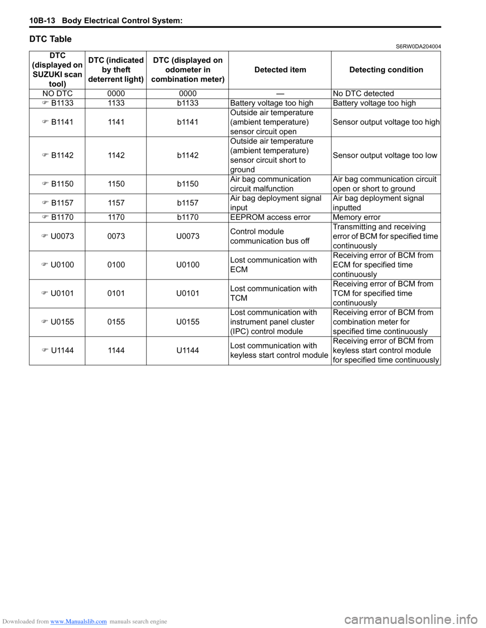
DTC TableS6RW0DA204004
DTC
(displayed on
SUZUKI scan
tool)DTC (indicated
by theft
deterrent light) DTC (displayed on
odometer in
combination meter) Detected item Detecting condition
NO DTC 0000 0000 — No DTC detected
�) B1133 1133 b1133 Battery voltage too high Battery voltage too high
�) B1141 1141 b1141Outside air temperature
(ambient temperature)
sensor circuit openSensor output voltage too high
�) B1142 1142 b1142Outside air temperature
(ambient temperature)
sensor circuit short to
groundSensor output voltage too low
�) B1150 1150 b1150Air bag communication
circuit malfunctionAir bag communication circuit
open or short to ground
�) B1157 1157 b1157Air bag deployment signal
inputAir bag deployment signal
inputted
�) B1170 1170 b1170 EEPROM access error Memory error
�) U0073 0073 U0073Control module
communication bus offTransmitting and receiving
error of BCM for specified time
continuously
�) U0100 0100 U0100Lost communication with
ECMReceiving error of BCM from
ECM for specified time
continuously
�) U0101 0101 U0101Lost communication with
TCMReceiving error of BCM from
TCM for specified time
continuously
�) U0155 0155 U0155Lost communication with
instrument panel cluster
(IPC) control moduleReceiving error of BCM from
combination meter for
specified time continuously
�) U1144 1144 U1144Lost communication with
keyless start control moduleReceiving error of BCM from
keyless start control module
for specified time continuously
Page 1502 of 1556
Downloaded from www.Manualslib.com manuals search engine 10B-29 Body Electrical Control System:
5) Disconnect connectors from BCM and junction
block.
6) Detach wiring harness clamp from junction block.
Installation
Reverse removal procedure for installation, noting
following points.
• Connect connectors securely.
• Enable air bag system referring to “Enabling Air Bag
System in Section 8B”.
• With keyless entry system (other than keyless start
model), if BCM is replaced, register transmitter code
into BCM, referring to “Programming Transmitter
Code for Keyless Entry System (Other than Keyless
Start Model) in Section 9F”.
Security Alarm Mode Selection Procedure (If
Equipped)
S6RW0DA206005
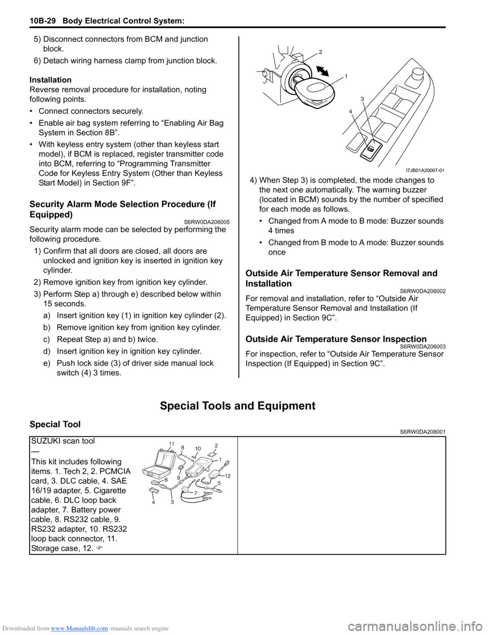
Security alarm mode can be selected by performing the
following procedure.
1) Confirm that all doors are closed, all doors are
unlocked and ignition key is inserted in ignition key
cylinder.
2) Remove ignition key from ignition key cylinder.
3) Perform Step a) through e) described below within
15 seconds.
a) Insert ignition key (1) in ignition key cylinder (2).
b) Remove ignition key from ignition key cylinder.
c) Repeat Step a) and b) twice.
d) Insert ignition key in ignition key cylinder.
e) Push lock side (3) of driver side manual lock
switch (4) 3 times.4) When Step 3) is completed, the mode changes to
the next one automatically. The warning buzzer
(located in BCM) sounds by the number of specified
for each mode as follows.
• Changed from A mode to B mode: Buzzer sounds
4 times
• Changed from B mode to A mode: Buzzer sounds
once
Outside Air Temperature Sensor Removal and
Installation
S6RW0DA206002
For removal and installation, refer to “Outside Air
Temperature Sensor Removal and Installation (If
Equipped) in Section 9C”.
Outside Air Temperature Sensor InspectionS6RW0DA206003
For inspection, refer to “Outside Air Temperature Sensor
Inspection (If Equipped) in Section 9C”.
Special Tools and Equipment
Special ToolS6RW0DA208001
1 2
4
3
I7JB01A20007-01
SUZUKI scan tool
—
This kit includes following
items. 1. Tech 2, 2. PCMCIA
card, 3. DLC cable, 4. SAE
16/19 adapter, 5. Cigarette
cable, 6. DLC loop back
adapter, 7. Battery power
cable, 8. RS232 cable, 9.
RS232 adapter, 10. RS232
loop back connector, 11.
Storage case, 12. �)
Page 1503 of 1556
Downloaded from www.Manualslib.com manuals search engine Immobilizer Control System: 10C-1
Control Systems
Immobilizer Control System
Precautions
Precautions in Diagnosing TroublesS6RW0DA300001
• Before confirming the diagnostic trouble code (DTC),
do not disconnect connector from ECM, battery cable
from battery, ground wire harness, or main fuse. Such
disconnection will erase DTC stored in ECM.
• DTC stored in ECM memory can be checked as well
as cleared by using SUZUKI scan tool. Before using
SUZUKI scan tool, read its operator’s manual
carefully to know how to use it and what functions are
available.
• Be sure to read “Precautions for Electrical Circuit
Service in Section 00” before inspection.
• Communication of ECM, BCM, ABS control module,
TCM (if equipped), 4WD control module (if equipped),
keyless start control module (if equipped),
combination meter and DLC is established by CAN
(Controller Area Network). Therefore, handle CAN
communication lines with care referring to “Precaution
for CAN Communication System in Section 00”.
For CAN communication system, refer to description
on “CAN Communication System Description in
Section 1A”.
Precaution in Replacing ECMS6RW0DA300002
• If ECM is replaced with new or used one without
Immobilizer control function, the engine will not be
started. In case of the above, check if the newly
installed ECM has Immobilizer control function.
• After ECM is replaced with new one or used one, the
transponder code in the transponder built in the
ignition key has to be registered with ECM. Or, the
engine cannot be started up. For the registration
procedure, refer to “Procedure after ECM
Replacement”.
Precaution in Replacing Ignition KeyS6RW0DA300003
To register ignition key in case of replacing key(s) and/or
making spare key(s), the transponder code in the ignition
key is registered with ECM. Or the engine can not be
started up. For the registration procedure, refer to
“Registration of the Ignition Key”.
Precautions in Handling Immobilizer Control
System
S6RW0DA300004
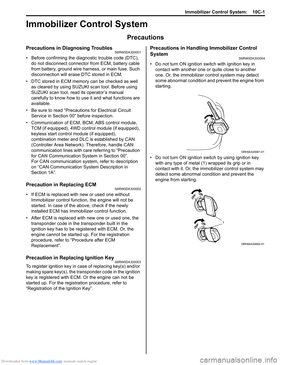
• Do not turn ON ignition switch with ignition key in
contact with another one or quite close to another
one. Or, the immobilizer control system may detect
some abnormal condition and prevent the engine from
starting.
• Do not turn ON ignition switch by using ignition key
with any type of metal (1) wrapped its grip or in
contact with it. Or, the immobilizer control system may
detect some abnormal condition and prevent the
engine from starting.
I3RH0AA30001-01
1
I3RH0AA30002-01
Page 1506 of 1556
Downloaded from www.Manualslib.com manuals search engine 10C-4 Immobilizer Control System:
BLK/WHT
BLK/ORN12V
G17-1
G17-2
12V
5V
12V
12VYEL/RED
YEL/BLK
G17-4
G17-3
5V
BRNBRN/YELBLK/YEL
1 2
22
2 34
251014
15
1 2 3
4 G17
[A]
5
6
G16-20 G16-29 G16-30 G146-3 G146-7 G146-8
WHT/RED
5V
5V
9
G16-18G16-19 E01-13
E01-28
BLU
RED
WHTE08-12
E08-1E01-18
E01-3
RED
WHTE08-13
E08-2
WHT
RED
G05-4
G05-2
12V
G05-35 8
11
G17-5WHT 76
G17-6WHT/RED
17
REDWHT
REDWHT
G241-10 G241-7
IG1
18
WHT
REDG05-1
G05-3
16 [C]
I6RW0DA30002-01
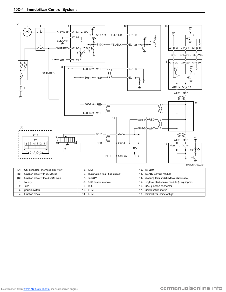
[A]: ICM connector (harness side view) 5. ICM 12. To SDM
[B]: Junction block with BCM type 6. Illumination ring (if equipped) 13. To ABS control module
[C]: Junction block without BCM type 7. To BCM 14. Steering lock unit (keyless start model)
1. Battery 8. ABS control module 15. Keyless start control module (if equipped)
2. Fuse 9. DLC 16. CAN junction connector
3. Ignition switch 10. ECM 17. Combination meter
4. Junction block 11. BCM 18. Immobilizer indicator light
Page 1518 of 1556
Downloaded from www.Manualslib.com manuals search engine 10C-16 Immobilizer Control System:
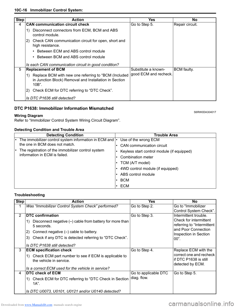
DTC P1638: Immobilizer Information MismatchedS6RW0DA304017
Wiring Diagram
Refer to “Immobilizer Control System Wiring Circuit Diagram”.
Detecting Condition and Trouble Area
Troubleshooting4CAN communication circuit check
1) Disconnect connectors from ECM, BCM and ABS
control module.
2) Check CAN communication circuit for open, short and
high resistance.
• Between ECM and ABS control module
• Between BCM and ABS control module
Is each CAN communication circuit in good condition?Go to Step 5. Repair circuit.
5Replacement of BCM
1) Replace BCM with new one referring to “BCM (Included
in Junction Block) Removal and Installation in Section
10B”.
2) Check ECM for DTC referring to “DTC Check”.
Is DTC P1636 still detected?Substitute a known-
good ECM and recheck.BCM faulty. Step Action Yes No
Detecting Condition Trouble Area
• The immobilizer control system information in ECM and
the one in BCM does not match.
• The registration of the immobilizer control system
information in ECM is failed.• Use of the wrong ECM
• CAN communication circuit
• Keyless start control module (if equipped)
• Combination meter
• TCM (A/T model)
• 4WD control module (if equipped)
• ABS control module
•BCM
•ECM
Step Action Yes No
1Was “Immobilizer Control System Check” performed?Go to Step 2. Go to “Immobilizer
Control System Check”.
2DTC confirmation
1) Disconnect negative (–) cable from battery for more than
5 seconds.
2) Connect negative (–) cable to battery.
3) Check if any DTC is detected referring to “DTC Check”.
Is DTC P1638 still detected?Go to Step 3. Intermittent trouble.
Check for intermittent
referring to “Intermittent
and Poor Connection
Inspection in Section
00”.
3ECM specification check
1) Check ECM part number to see if ECM is applicable to
the vehicle in service.
Is a correct ECM used for the vehicle in service?Go to Step 4. Replace ECM with the
correct one and recheck
if DTC P1638 is still
detected by ECM.
4DTC check of ECM
1) Check ECM for DTC referring to “DTC Check in Section
1A”.
Is DTC U0073, U0101, U0121 and/or U0140 detected?Go to applicable DTC
diag. flow.Go to Step 5.
Page 1521 of 1556
Downloaded from www.Manualslib.com manuals search engine Immobilizer Control System: 10C-19
Repair Instructions
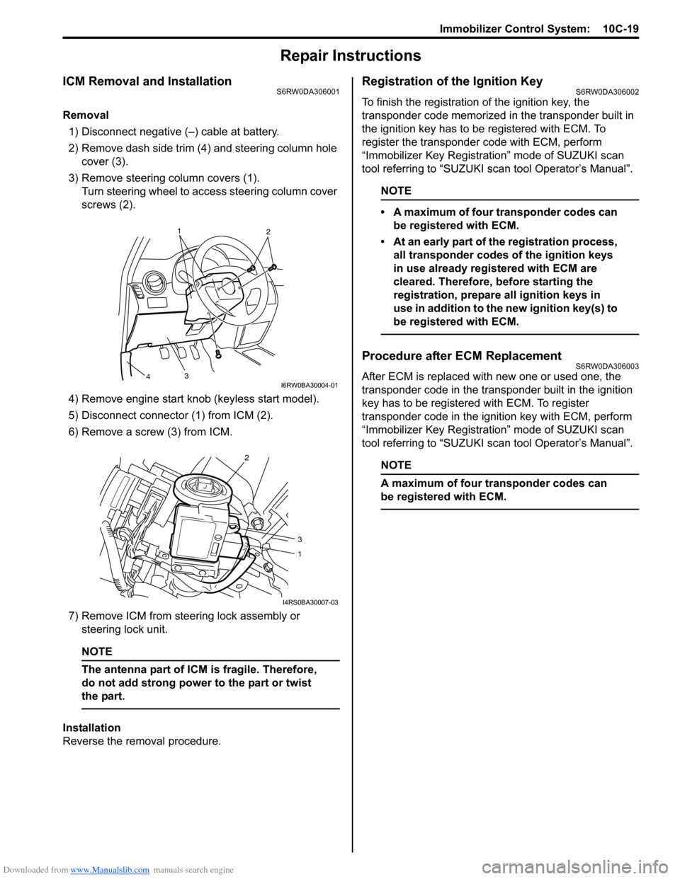
ICM Removal and InstallationS6RW0DA306001
Removal
1) Disconnect negative (–) cable at battery.
2) Remove dash side trim (4) and steering column hole
cover (3).
3) Remove steering column covers (1).
Turn steering wheel to access steering column cover
screws (2).
4) Remove engine start knob (keyless start model).
5) Disconnect connector (1) from ICM (2).
6) Remove a screw (3) from ICM.
7) Remove ICM from steering lock assembly or
steering lock unit.
NOTE
The antenna part of ICM is fragile. Therefore,
do not add strong power to the part or twist
the part.
Installation
Reverse the removal procedure.
Registration of the Ignition KeyS6RW0DA306002
To finish the registration of the ignition key, the
transponder code memorized in the transponder built in
the ignition key has to be registered with ECM. To
register the transponder code with ECM, perform
“Immobilizer Key Registration” mode of SUZUKI scan
tool referring to “SUZUKI scan tool Operator’s Manual”.
NOTE
• A maximum of four transponder codes can
be registered with ECM.
• At an early part of the registration process,
all transponder codes of the ignition keys
in use already registered with ECM are
cleared. Therefore, before starting the
registration, prepare all ignition keys in
use in addition to the new ignition key(s) to
be registered with ECM.
Procedure after ECM ReplacementS6RW0DA306003
After ECM is replaced with new one or used one, the
transponder code in the transponder built in the ignition
key has to be registered with ECM. To register
transponder code in the ignition key with ECM, perform
“Immobilizer Key Registration” mode of SUZUKI scan
tool referring to “SUZUKI scan tool Operator’s Manual”.
NOTE
A maximum of four transponder codes can
be registered with ECM.
1
2
3
4I6RW0BA30004-01
2
3
1
I4RS0BA30007-03
Page 1535 of 1556
Downloaded from www.Manualslib.com manuals search engine Keyless Start System: 10E-13
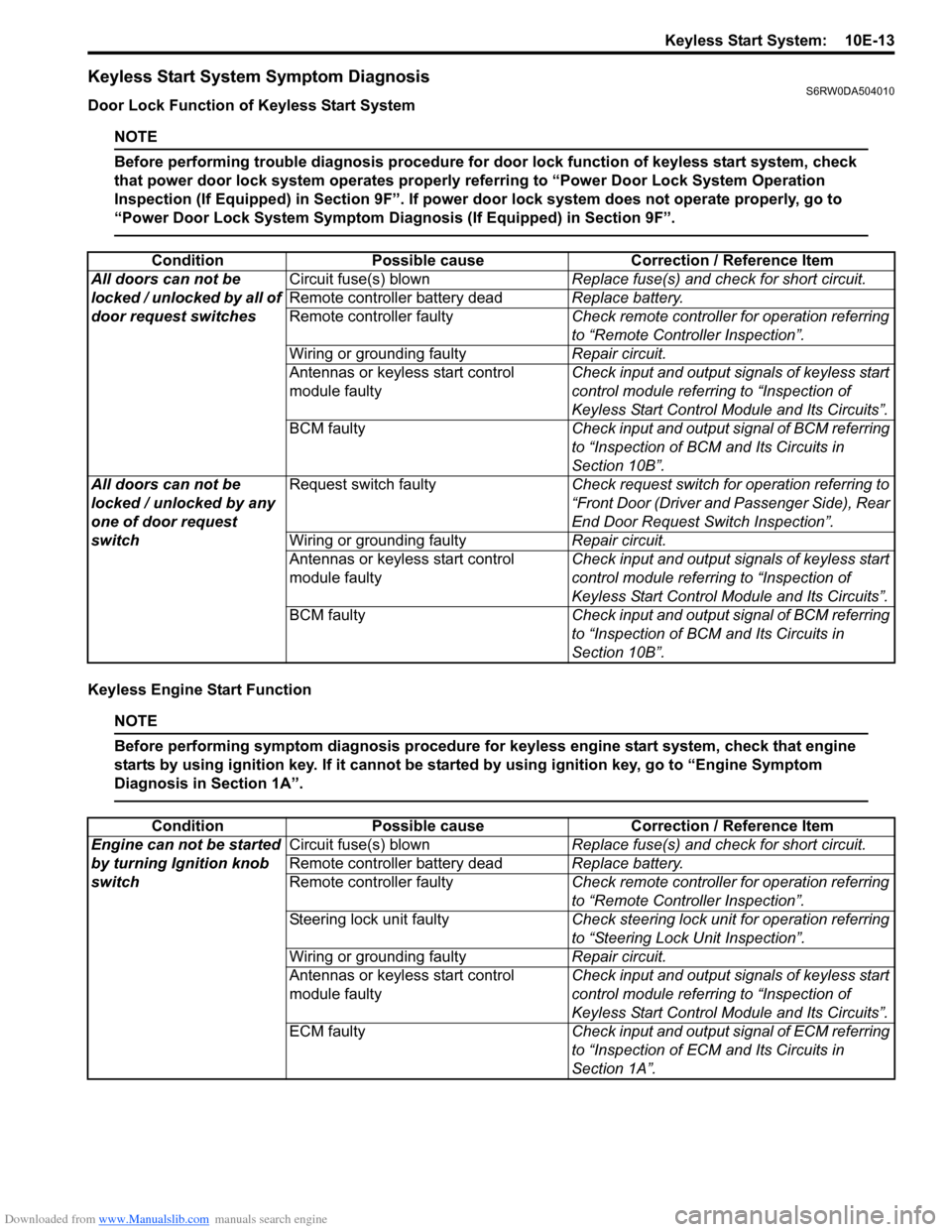
Keyless Start System Symptom DiagnosisS6RW0DA504010
Door Lock Function of Keyless Start System
NOTE
Before performing trouble diagnosis procedure for door lock function of keyless start system, check
that power door lock system operates properly referring to “Power Door Lock System Operation
Inspection (If Equipped) in Section 9F”. If power door lock system does not operate properly, go to
“Power Door Lock System Symptom Diagnosis (If Equipped) in Section 9F”.
Keyless Engine Start Function
NOTE
Before performing symptom diagnosis procedure for keyless engine start system, check that engine
starts by using ignition key. If it cannot be started by using ignition key, go to “Engine Symptom
Diagnosis in Section 1A”.
Condition Possible cause Correction / Reference Item
All doors can not be
locked / unlocked by all of
door request switchesCircuit fuse(s) blownReplace fuse(s) and check for short circuit.
Remote controller battery deadReplace battery.
Remote controller faultyCheck remote controller for operation referring
to “Remote Controller Inspection”.
Wiring or grounding faultyRepair circuit.
Antennas or keyless start control
module faultyCheck input and output signals of keyless start
control module referring to “Inspection of
Keyless Start Control Module and Its Circuits”.
BCM faultyCheck input and output signal of BCM referring
to “Inspection of BCM and Its Circuits in
Section 10B”.
All doors can not be
locked / unlocked by any
one of door request
switchRequest switch faultyCheck request switch for operation referring to
“Front Door (Driver and Passenger Side), Rear
End Door Request Switch Inspection”.
Wiring or grounding faultyRepair circuit.
Antennas or keyless start control
module faultyCheck input and output signals of keyless start
control module referring to “Inspection of
Keyless Start Control Module and Its Circuits”.
BCM faultyCheck input and output signal of BCM referring
to “Inspection of BCM and Its Circuits in
Section 10B”.
Condition Possible cause Correction / Reference Item
Engine can not be started
by turning Ignition knob
switchCircuit fuse(s) blownReplace fuse(s) and check for short circuit.
Remote controller battery deadReplace battery.
Remote controller faultyCheck remote controller for operation referring
to “Remote Controller Inspection”.
Steering lock unit faultyCheck steering lock unit for operation referring
to “Steering Lock Unit Inspection”.
Wiring or grounding faultyRepair circuit.
Antennas or keyless start control
module faultyCheck input and output signals of keyless start
control module referring to “Inspection of
Keyless Start Control Module and Its Circuits”.
ECM faultyCheck input and output signal of ECM referring
to “Inspection of ECM and Its Circuits in
Section 1A”.
Page 1537 of 1556
Downloaded from www.Manualslib.com manuals search engine Keyless Start System: 10E-15
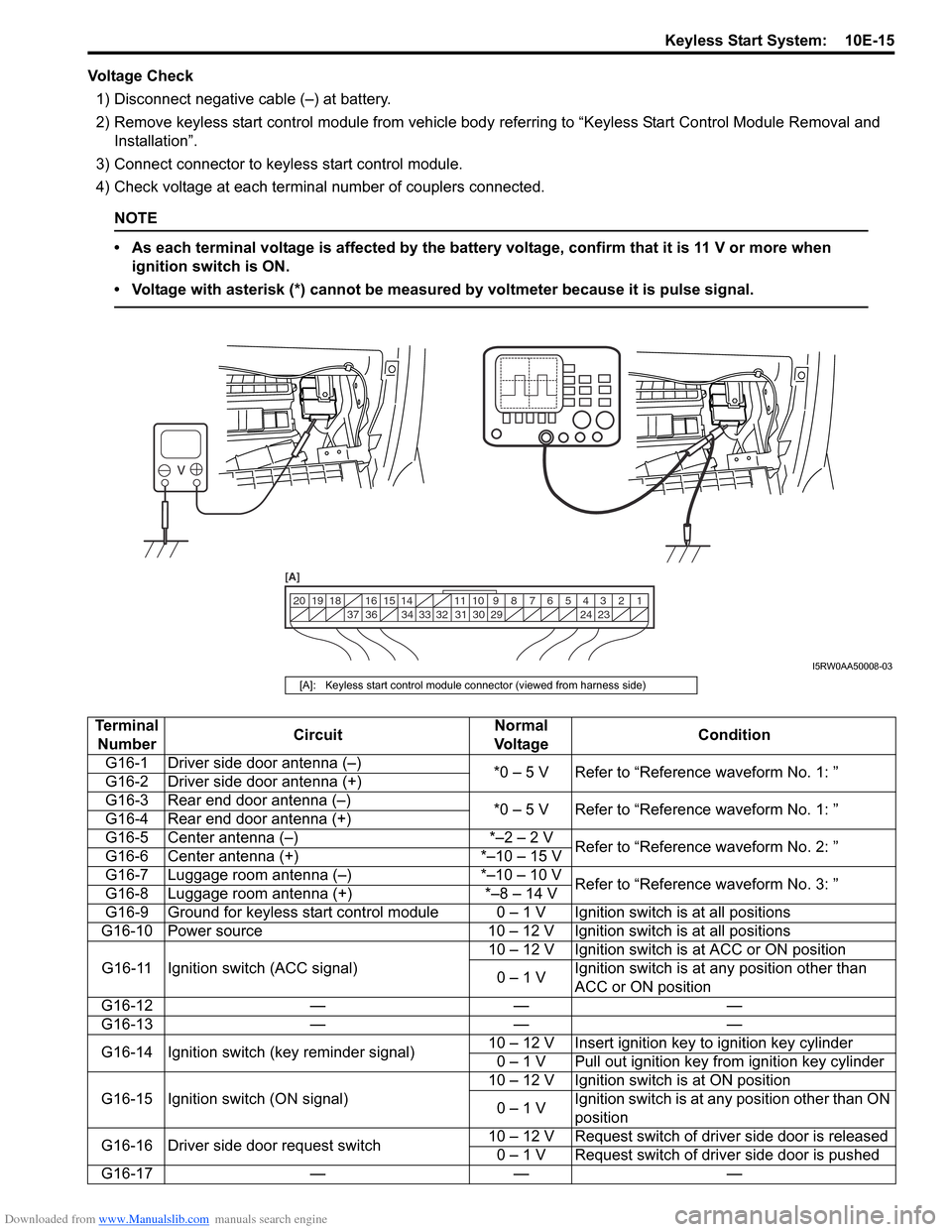
Voltage Check
1) Disconnect negative cable (–) at battery.
2) Remove keyless start control module from vehicle body referring to “Keyless Start Control Module Removal and
Installation”.
3) Connect connector to keyless start control module.
4) Check voltage at each terminal number of couplers connected.
NOTE
• As each terminal voltage is affected by the battery voltage, confirm that it is 11 V or more when
ignition switch is ON.
• Voltage with asterisk (*) cannot be measured by voltmeter because it is pulse signal.
1 2 3 4 5 6 7 8 9 10 11 14 15 16
36 34 33 32 31 30 29 24 23 37 18 19 20
[A]
I5RW0AA50008-03
[A]: Keyless start control module connector (viewed from harness side)
Terminal
NumberCircuitNormal
Vo l ta g eCondition
G16-1 Driver side door antenna (–)
*0 – 5 V Refer to “Reference waveform No. 1: ”
G16-2 Driver side door antenna (+)
G16-3 Rear end door antenna (–)
*0 – 5 V Refer to “Reference waveform No. 1: ”
G16-4 Rear end door antenna (+)
G16-5 Center antenna (–) *–2 – 2 V
Refer to “Reference waveform No. 2: ”
G16-6 Center antenna (+) *–10 – 15 V
G16-7 Luggage room antenna (–) *–10 – 10 V
Refer to “Reference waveform No. 3: ”
G16-8 Luggage room antenna (+) *–8 – 14 V
G16-9 Ground for keyless start control module 0 – 1 V Ignition switch is at all positions
G16-10 Power source 10 – 12 V Ignition switch is at all positions
G16-11 Ignition switch (ACC signal)10 – 12 V Ignition switch is at ACC or ON position
0 – 1 VIgnition switch is at any position other than
ACC or ON position
G16-12 — — —
G16-13 — — —
G16-14 Ignition switch (key reminder signal)10 – 12 V Insert ignition key to ignition key cylinder
0 – 1 V Pull out ignition key from ignition key cylinder
G16-15 Ignition switch (ON signal)10 – 12 V Ignition switch is at ON position
0 – 1 VIgnition switch is at any position other than ON
position
G16-16 Driver side door request switch10 – 12 V Request switch of driver side door is released
0 – 1 V Request switch of driver side door is pushed
G16-17 — — —