2006 SUZUKI SX4 set clock
[x] Cancel search: set clockPage 11 of 1556

Downloaded from www.Manualslib.com manuals search engine Precautions: 00-4
WARNING!
• Whenever raising a vehicle for service, be
sure to follow the instructions under
“Vehicle Lifting Points in Section 0A”.
• When it is necessary to do service work
with the engine running, make sure that
the parking brake is set fully and the
transmission is in Neutral (for manual
transmission vehicles) or Park (for
automatic transmission vehicles), Keep
hands, hair, clothing, tools, etc. away from
the fan and belts when the engine is
running.
• When it is necessary to run the engine
indoors, make sure that the exhaust gas is
forced outdoors.
• Do not perform service work in areas
where combustible materials can come in
contact with a hot exhaust system. When
working with toxic or flammable materials
(such as gasoline and refrigerant), make
sure that the area you work in is well-
ventilated.
• To avoid getting burned, keep away from
hot metal parts such as the radiator,
exhaust manifold, tail pipe, muffler, etc.
• New and used engine oil can be
hazardous. Children and pets may be
harmed by swallowing new or used oil.
Keep new and used oil and used engine oil
filters away from children and pets.
Continuous contact with used engine oil
has been found to cause [skin] cancer in
laboratory animals. Brief contact with used
oil may irritate skin. To minimize your
exposure to used engine oil, wear a long-
sleeve shirt and moisture-proof gloves
(such as dish washing gloves) when
changing engine oil. If engine oil contacts
your skin, wash thoroughly with soap and
water. Launder any clothing or rags if wet
with oil, recycle or properly dispose of
used oil and filters.
• Be sure to observe following instructions
when handling service materials such as
fuel, oil, fluid, coolant, grease, sealant,
thread lock cement, etc. Otherwise, your
health may be ruined.
– Whenever handling any of these service
materials, wear safety glasses to protect
your eyes. If it gets into your eye, it may
cause inflammation.
– Whenever handling any of these service
materials, wear moisture-proof gloves to
protect your skin. If it adheres to your
skin, it may cause inflammation.– Do not swallow any of these service
materials. It would cause diarrhea or
nausea.
– Keep all these materials out of children’s
reach.
• Make sure the bonnet is fully closed and
latched before driving. If it is not, it can fly
up unexpectedly during driving,
obstructing your view and resulting in an
accident.
• Before starting any service work, cover fenders, seats
and any other parts that are likely to get scratched or
stained during servicing. Also, be aware that what you
wear (e.g., buttons) may cause damage to the
vehicle’s finish.
• When performing service to electrical parts that does
not require use of battery power, disconnect the
negative cable of the battery.
• When disconnecting the negative cable from the
battery, be careful to the following.
– Check and record DTCs in ECM, HVAC control
module and/or PS control module if necessary
before disconnecting.
– Record displayed contents of the clock and/or
audio system, etc. before disconnecting and reset it
as before after connecting.
– For vehicle equipped with electric throttle body
system, perform electric throttle body system
calibration referring to “Electric Throttle Body
System Calibration in Section 1C” after
reconnecting the negative cable to the battery.
I2RH01010025-01
I2RH01010026-01
Page 539 of 1556

Downloaded from www.Manualslib.com manuals search engine Differential: 3B-42
14) Set dial gauge to bevel pinion mounting dummy and
make 0 (zero) adjustment on surface plate.
NOTE
• When setting dial gauge to mounting
dummy, tighten screw lightly. Be careful
not to overtighten it, which will cause
damage to dial gauge.
• With dial gauge set, turn dummy back and
forth by hand a couple of times and attain
accurate 0 (zero) adjustment.
• It is desirable that short pointer indicates
beyond 2 mm when long one is at 0 (zero).
15) Place zero-adjusted mounting dummy (1) and dial
gauge set on pinion dummy (2) and take
measurement between zero position and extended
dial gauge measuring tip.
NOTE
• Repeat turning back and forth of dummy
and measure distance as far as top surface
of pinion dummy accurately.
• When dial gauge measuring tip extends
from 0 (zero) position, pointer turns
counterclockwise.
16) Necessary adjusting shim thickness is the same
value as measured value by dial gauge.
17) Select adjusting shim(s) (2) closest to obtained value
from among the following available sizes and put it in
place and then press-fit rear bearing (1) to bevel
pinion (3).
Available shim thickness
0.30, 0.60, 0.63, 0.66, 0.69, 0.72, 0.75, 0.78, 0.81,
0.84 and 0.87 mm (0.012, 0.023, 0.024, 0.026,
0.027, 0.028, 0.030, 0.031, 0.032, 0.033 and 0.034
in.)
Special tool
(D): 09925–18011
18) With new pinion spacer (2) inserted as shown in
figure, install front bearing (1) to differential carrier
(3).
NOTE
Apply differential oil to front and rear
bearings.
I5RW0A320051-01
1
2
I5RW0A320052-01
Necessary shim thickness
“e”= Dial gauge measured
value “c”
I3RH01322055-01
I5RW0A320053-01
Page 874 of 1556

Downloaded from www.Manualslib.com manuals search engine 6B-5 Steering Wheel and Column:
4) Connect horn connector and audio control switch
connector, if necessary.
5) Install driver air bag (inflator) module to steering
wheel. Refer to “Driver Air Bag (Inflator) Module
Removal and Installation in Section 8B”.
6) Connect negative (–) cable to battery.
7) Enable air bag system referring to “Enabling Air Bag
System in Section 8B”.
Contact Coil Cable Assembly Removal and
Installation
S6RW0D6206003
CAUTION!
Do not turn contact coil more than allowable
number of turns (about two and a half turns
from the center position clockwise or
counterclockwise respectively), or coil will
break.
Removal
1) Disconnect negative (–) cable at battery.
2) Disable air bag system referring to “Disabling Air
Bag System in Section 8B”.
3) Remove steering wheel from steering column
referring to “Steering Wheel Removal and
Installation”.
4) Remove steering column hole cover.
5) Remove steering column lower cover (2) and upper
cover (1).6) Remove contact coil cable assembly (1) from
steering column.
Installation
1) Check to make sure that vehicle’s front tires are set
at straight-ahead position and then ignition switch is
at LOCK position.
2) Install contact coil cable assembly to steering
column securely.
NOTE
New contact coil cable assembly is supplied
with contact coil set and held at its center
position with a lock pin (1). Remove this lock
pin after installing contact coil cable
assembly to steering column.
2
1
I6RW0B620005-01
1I6RW0B620009-02
I4RS0A620010-01
Page 875 of 1556

Downloaded from www.Manualslib.com manuals search engine Steering Wheel and Column: 6B-6
3) Install steering column upper cover (1) and lower
cover (2).
CAUTION!
When installing covers, be careful so that
each lead wire is not caught between covers.
Otherwise, each lead wire is damaged.
4) Install steering wheel to steering column. Refer to
“Steering Wheel Removal and Installation”.
5) Connect negative (–) cable to battery.
6) Enable air bag system referring to “Enabling Air Bag
System in Section 8B”.
Centering Contact Coil Cable AssemblyS6RW0D6206004
1) Check that vehicle’s wheels (front tires) are set at
straight-ahead position.
2) Check that ignition switch is at LOCK position.
3) Turn contact coil counterclockwise slowly with a light
force till contact coil will not turn any further.
NOTE
Contact coil can turn about 5 turns at the
maximum, that is, if it is at the center
position, can turn about two and a half turns
both clockwise and counterclockwise.
4) From the position where contact coil became unable
to turn any further (it stopped), turn it back clockwise
about two and a half rotations and align center mark
with alignment mark (1).
Contact Coil Cable Assembly InspectionS6RW0D6206005
Refer to “Contact Coil Cable and Its Circuit Check in
Section 8B”.
Steering Column Removal and InstallationS6RW0D6206008
CAUTION!
Once the steering column is removed from
the vehicle, the column is extremely
susceptible to damage.
• Dropping the column assembly on its end
could collapse the steering shaft or loosen
the plastic shear pins which maintain
column length.
• Leaning on the column assembly could
cause it to bend or deform.
Any of the damage could impair the column’s
collapsible design.
Steering column mounting nuts should not
be loosened with steering shaft joint upper
side bolt tightened as this could cause
damage to shaft joint bearing.
NOTE
When servicing steering column or any
column-mounted component, remove
steering wheel. But when removing steering
column simply to gain access to instrument
panel components, leave steering wheel
installed on steering column.
3. Standard screw 4. Tapping screw
2
1
3
4
I6RW0B620003-01
I4RS0A620012-01
1
I4RS0A620013-01
Page 961 of 1556

Downloaded from www.Manualslib.com manuals search engine Air Conditioning System: Manual Type 7B-21
7) When refrigerant container (1) is emptied, use the
following procedure to replace it with a new
refrigerant container.
a) Close low pressure valve.
b) Replace empty container with a refrigerant
container which has been charged with
refrigerant. When using refrigerant container tap
valve (2), use the following procedure for
replacement.
i) Retract needle (3) and remove refrigerant
container tap valve by loosening its plate nut
(4).
ii) Install the refrigerant container tap valve to a
new refrigerant container.
c) Purge any air existing in center charging hose.
When using refrigerant container tap valve, use
the following procedure to purge air.
i) Once fully tighten refrigerant container tap
valve (1), and then loosen (open) plate nut
(2) slightly.
ii) Open low pressure side valve (3) of manifold
gauge set (4) a little.
iii) As soon as refrigerant comes out with a
“hiss” through a clearance between
refrigerant container and tap valve, tighten
plate nut as well as low pressure side valve.
iv) Turn handle of tap valve clockwise so that its
needle is screwed into the new container to
make a hole for refrigerant flow.8) After the system has been charged with specified
amount of refrigerant or when low pressure gauge
(1) and high pressure gauge (2) have indicated the
following specified value, close low pressure side
valve (3) on manifold gauge set (4).
Specified amount of refrigerant
430 ± 20 g (15.2 ± 0.7 oz))
Low side and high side pressure example
Removal of Manifold Gauge Set
WARNING!
High pressure side is under high pressure.
Therefore, be careful not to get injured
especially on your eyes and skin.
For the A/C system charged with the specified amount of
refrigerant, remove manifold gauge set as follows:
1) Close low pressure side valve of manifold gauge set.
(The high pressure side valve is closed continuously
during the process of charging.)
2) Close refrigerant container valve.
3) Stop engine.
4) Using shop rag, remove charging hoses from service
valves. This operation must be performed quickly.
5) Put caps on service valves.
I2RH01720018-01
I2RH01720019-01
Gauges should read as follows when ambient
temperature is 30 °C (86 °F).
Pressure
on high pressure gauge1130 – 1560 kPa
(11.4 – 15.6 kgf/cm
2)
(162.3 – 221.8 psi)
Pressure
on low pressure gauge270 – 390 kPa
(2.7 – 3.9 kgf/cm
2)
(38.8 – 56.0 psi)
4
2
1
3
I7RW01721013-02
Page 1339 of 1556

Downloaded from www.Manualslib.com manuals search engine Lighting Systems: 9B-20
Igniter Removal and Installation (Discharge
Headlight Model)
S6RW0D9206024
WARNING!
Be sure to read “Precautions for Discharge
Headlight Service (If Equipped)” carefully
before working. Neglecting them may result
in personal injury.
Removal
1) Remove ballast referring to “Ballast Removal and
Installation (Discharge Headlight Model)”.
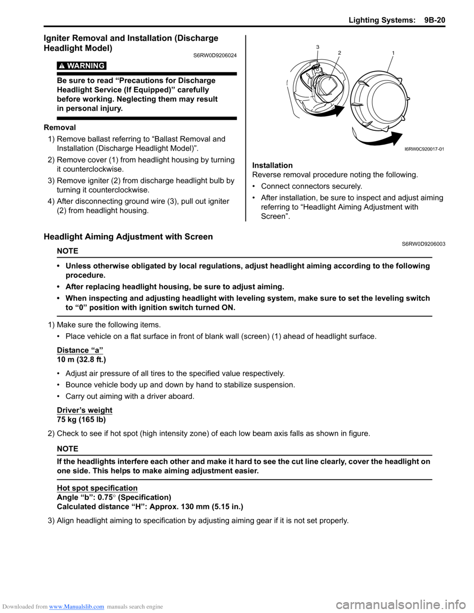
2) Remove cover (1) from headlight housing by turning
it counterclockwise.
3) Remove igniter (2) from discharge headlight bulb by
turning it counterclockwise.
4) After disconnecting ground wire (3), pull out igniter
(2) from headlight housing.Installation
Reverse removal procedure noting the following.
• Connect connectors securely.
• After installation, be sure to inspect and adjust aiming
referring to “Headlight Aiming Adjustment with
Screen”.
Headlight Aiming Adjustment with ScreenS6RW0D9206003
NOTE
• Unless otherwise obligated by local regulations, adjust headlight aiming according to the following
procedure.
• After replacing headlight housing, be sure to adjust aiming.
• When inspecting and adjusting headlight with leveling system, make sure to set the leveling switch
to “0” position with ignition switch turned ON.
1) Make sure the following items.
• Place vehicle on a flat surface in front of blank wall (screen) (1) ahead of headlight surface.
Distance “a”
10 m (32.8 ft.)
• Adjust air pressure of all tires to the specified value respectively.
• Bounce vehicle body up and down by hand to stabilize suspension.
• Carry out aiming with a driver aboard.
Driver’s weight
75 kg (165 lb)
2) Check to see if hot spot (high intensity zone) of each low beam axis falls as shown in figure.
NOTE
If the headlights interfere each other and make it hard to see the cut line clearly, cover the headlight on
one side. This helps to make aiming adjustment easier.
Hot spot specification
Angle “b”: 0.75° (Specification)
Calculated distance “H”: Approx. 130 mm (5.15 in.)
3) Align headlight aiming to specification by adjusting aiming gear if it is not set properly.
2
1 3
I6RW0C920017-01
Page 1363 of 1556

Downloaded from www.Manualslib.com manuals search engine Instrumentation / Driver Info. / Horn: 9C-11
Clock System Diagnosis (If Equipped)S6RW0D9304016
Display of thermometer
does not change at 50
°C
(122
°F)Outside air temperature is 50 °C (122
°F) or more—
Outside air temperature sensor faultyCheck outside air temperature sensor referring
to “Outside Air Temperature Sensor Inspection
(If Equipped)”.
Information display unit faultyReplace unit.
BCM faultyReplace after making sure that none of above
parts is faulty.
Display of thermometer
does not change at “- - -
°C (°F)”Outside air temperature sensor faultyCheck outside air temperature sensor referring
to “Outside Air Temperature Sensor Inspection
(If Equipped)”.
Outside air temperature sensor circuit is
open or shortRepair circuit.
Wiring or grounding faultyRepair circuit.
Information display unit faultyReplace unit.
BCM faultyReplace after making sure that none of above
parts is faulty.
Display of fuel
consumption does not
change at “- - - l / 100 km
(km/l, MPG)”Vehicle is not running (instantaneous
fuel consumption mode)—
Fuel consumption was reset (average
fuel consumption mode, if equipped)Vehicle runs for a while.
Vehicle speed signal faultyCheck ECM for DTC referring to “DTC Check
in Section 1A”.
Wiring or grounding faultyRepair circuit.
CAN communication data (information)
can not be received by BCMCheck BCM for DTC referring to “DTC Check
in Section 10B”.
Information display unit faultyReplace unit.
BCM faultyReplace after making sure that none of above
parts is faulty. Condition Possible cause Correction / Reference Item
Condition Possible cause Correction / Reference Item
No displaying of clockCircuit fuse blownReplace fuse and check for short circuit.
Wiring or grounding faultyRepair circuit.
Clock unit faultyReplace unit.
Page 1520 of 1556

Downloaded from www.Manualslib.com manuals search engine 10C-18 Immobilizer Control System:
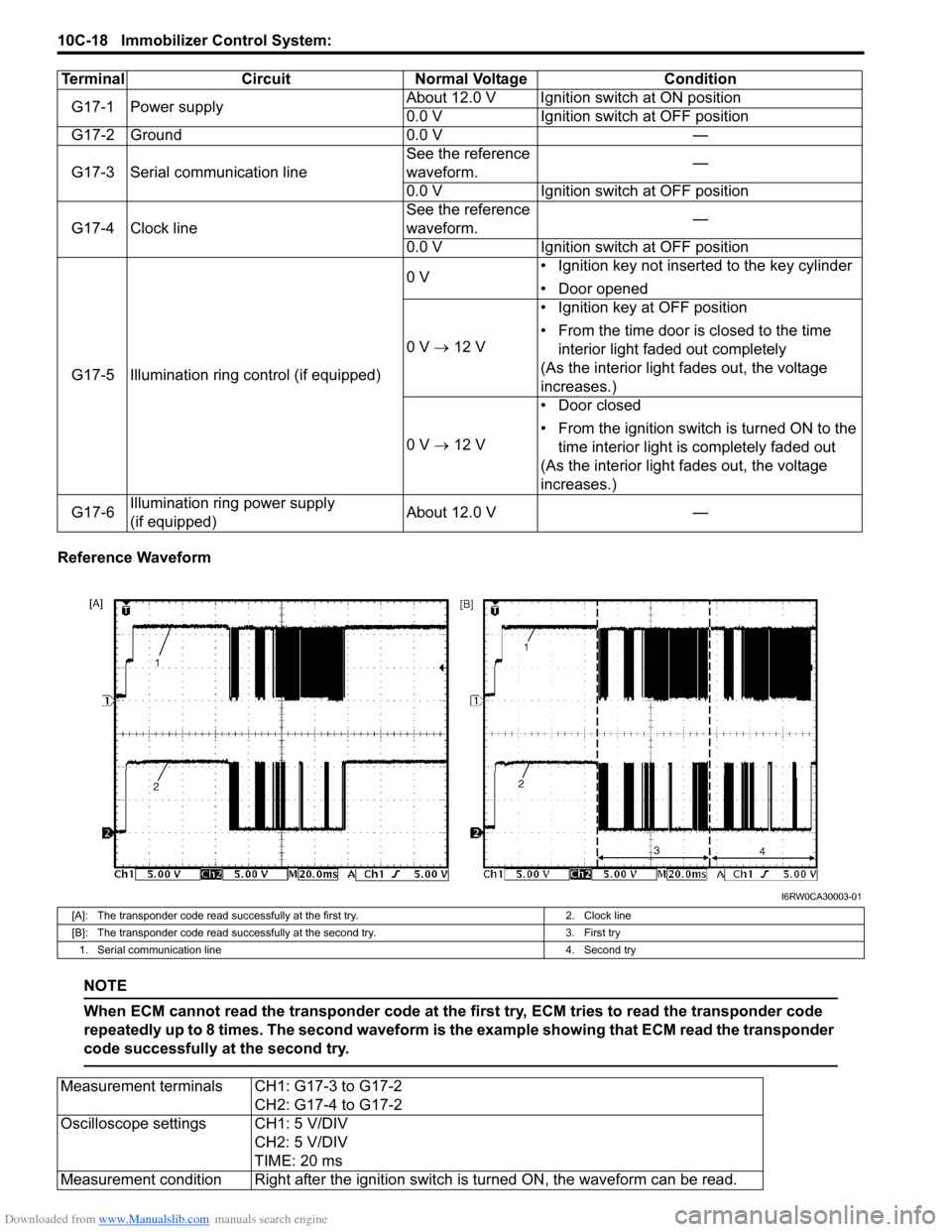
Reference Waveform
NOTE
When ECM cannot read the transponder code at the first try, ECM tries to read the transponder code
repeatedly up to 8 times. The second waveform is the example showing that ECM read the transponder
code successfully at the second try.
Terminal Circuit Normal Voltage Condition
G17-1 Power supplyAbout 12.0 V Ignition switch at ON position
0.0 V Ignition switch at OFF position
G17-2 Ground 0.0 V —
G17-3 Serial communication lineSee the reference
waveform.—
0.0 V Ignition switch at OFF position
G17-4 Clock lineSee the reference
waveform.—
0.0 V Ignition switch at OFF position
G17-5 Illumination ring control (if equipped)0 V• Ignition key not inserted to the key cylinder
• Door opened
0 V → 12 V• Ignition key at OFF position
• From the time door is closed to the time
interior light faded out completely
(As the interior light fades out, the voltage
increases.)
0 V → 12 V• Door closed
• From the ignition switch is turned ON to the
time interior light is completely faded out
(As the interior light fades out, the voltage
increases.)
G17-6Illumination ring power supply
(if equipped)About 12.0 V —
I6RW0CA30003-01
[A]: The transponder code read successfully at the first try. 2. Clock line
[B]: The transponder code read successfully at the second try. 3. First try
1. Serial communication line 4. Second try
Measurement terminals CH1: G17-3 to G17-2
CH2: G17-4 to G17-2
Oscilloscope settings CH1: 5 V/DIV
CH2: 5 V/DIV
TIME: 20 ms
Measurement condition Right after the ignition switch is turned ON, the waveform can be read.