2006 SUZUKI SX4 cable
[x] Cancel search: cablePage 1372 of 1556
Downloaded from www.Manualslib.com manuals search engine 9C-20 Instrumentation / Driver Info. / Horn:
GPS Antenna Removal and Installation (If
Equipped)
S6RW0D9306027
Removal
1) Remove combination meter cluster panel referring to
step 1) to 4) of “Combination Meter Removal and
Installation”.
2) Disconnect GPS antenna connector from navigation
unit referring to “Audio Unit Removal and Installation
(If Equipped)”.
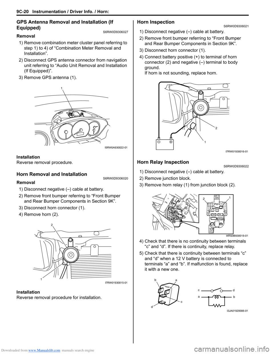
3) Remove GPS antenna (1).
Installation
Reverse removal procedure.
Horn Removal and InstallationS6RW0D9306020
Removal
1) Disconnect negative (–) cable at battery.
2) Remove front bumper referring to “Front Bumper
and Rear Bumper Components in Section 9K”.
3) Disconnect horn connector (1).
4) Remove horn (2).
Installation
Reverse removal procedure for installation.
Horn InspectionS6RW0D9306021
1) Disconnect negative (–) cable at battery.
2) Remove front bumper referring to “Front Bumper
and Rear Bumper Components in Section 9K”.
3) Disconnect horn connector (1).
4) Connect battery positive (+) to terminal of horn
connector (2) and negative (–) terminal to body
ground.
If horn is not sounding, replace horn.
Horn Relay InspectionS6RW0D9306022
1) Disconnect negative (–) cable at battery.
2) Remove junction block.
3) Remove horn relay (1) from junction block (2).
4) Check that there is no continuity between terminals
“c” and “d”. If there is continuity, replace relay.
5) Check that there is continuity between terminals “c”
and “d” when a 12 V battery is connected to
terminals “a” and “b”. If malfunction is found, replace
it with a new one.
1
I5RW0A930022-01
12I7RW01930015-01
12
I7RW01930016-01
1
2
I4RS0B930018-01
ba
c
dc
ad
bI3JA01920006-01
Page 1377 of 1556
Downloaded from www.Manualslib.com manuals search engine Wipers / Washers: 9D-3
Washer Tank and Washer Pump Removal and
Installation
S6RW0D9406002
Removal
1) Disconnect negative (–) cable at battery.
2) Remove front bumper referring to “Front Bumper
and Rear Bumper Components in Section 9K”.
3) Disconnect washer pump lead wire couplers and
hoses.
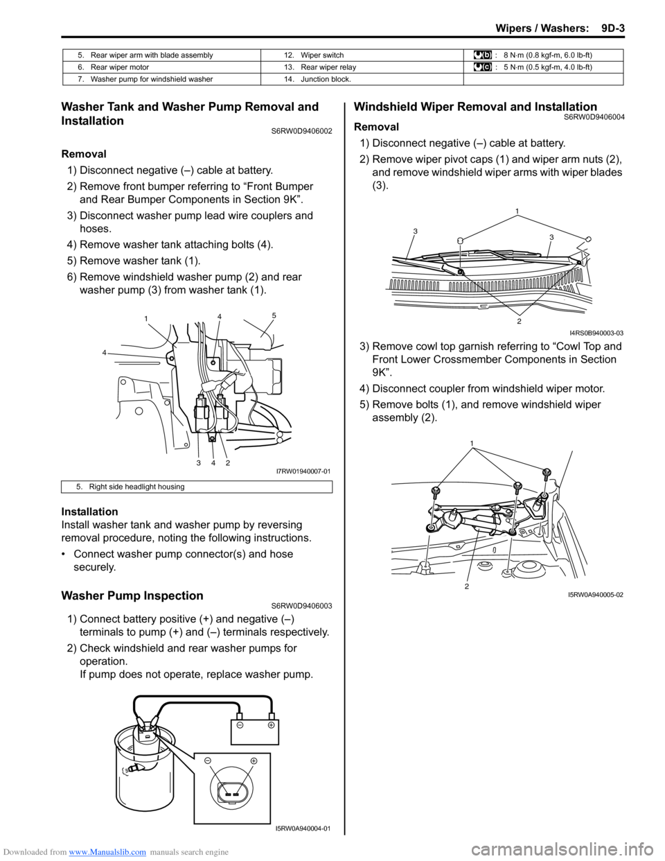
4) Remove washer tank attaching bolts (4).
5) Remove washer tank (1).
6) Remove windshield washer pump (2) and rear
washer pump (3) from washer tank (1).
Installation
Install washer tank and washer pump by reversing
removal procedure, noting the following instructions.
• Connect washer pump connector(s) and hose
securely.
Washer Pump InspectionS6RW0D9406003
1) Connect battery positive (+) and negative (–)
terminals to pump (+) and (–) terminals respectively.
2) Check windshield and rear washer pumps for
operation.
If pump does not operate, replace washer pump.
Windshield Wiper Removal and InstallationS6RW0D9406004
Removal
1) Disconnect negative (–) cable at battery.
2) Remove wiper pivot caps (1) and wiper arm nuts (2),
and remove windshield wiper arms with wiper blades
(3).
3) Remove cowl top garnish referring to “Cowl Top and
Front Lower Crossmember Components in Section
9K”.
4) Disconnect coupler from windshield wiper motor.
5) Remove bolts (1), and remove windshield wiper
assembly (2).
5. Rear wiper arm with blade assembly 12. Wiper switch : 8 N⋅m (0.8 kgf-m, 6.0 lb-ft)
6. Rear wiper motor 13. Rear wiper relay : 5 N⋅m (0.5 kgf-m, 4.0 lb-ft)
7. Washer pump for windshield washer 14. Junction block.
5. Right side headlight housing
1
4
34245
I7RW01940007-01
I5RW0A940004-01
1
3 3
2
I4RS0B940003-03
21I5RW0A940005-02
Page 1378 of 1556
Downloaded from www.Manualslib.com manuals search engine 9D-4 Wipers / Washers:
Installation
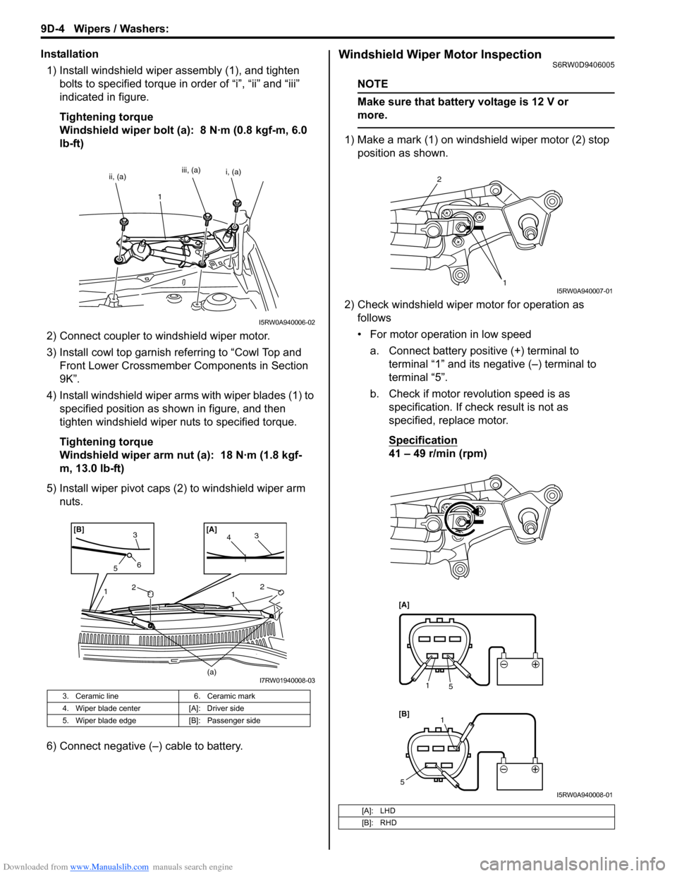
1) Install windshield wiper assembly (1), and tighten
bolts to specified torque in order of “i”, “ii” and “iii”
indicated in figure.
Tightening torque
Windshield wiper bolt (a): 8 N·m (0.8 kgf-m, 6.0
lb-ft)
2) Connect coupler to windshield wiper motor.
3) Install cowl top garnish referring to “Cowl Top and
Front Lower Crossmember Components in Section
9K”.
4) Install windshield wiper arms with wiper blades (1) to
specified position as shown in figure, and then
tighten windshield wiper nuts to specified torque.
Tightening torque
Windshield wiper arm nut (a): 18 N·m (1.8 kgf-
m, 13.0 lb-ft)
5) Install wiper pivot caps (2) to windshield wiper arm
nuts.
6) Connect negative (–) cable to battery.Windshield Wiper Motor InspectionS6RW0D9406005
NOTE
Make sure that battery voltage is 12 V or
more.
1) Make a mark (1) on windshield wiper motor (2) stop
position as shown.
2) Check windshield wiper motor for operation as
follows
• For motor operation in low speed
a. Connect battery positive (+) terminal to
terminal “1” and its negative (–) terminal to
terminal “5”.
b. Check if motor revolution speed is as
specification. If check result is not as
specified, replace motor.
Specification
41 – 49 r/min (rpm)
3. Ceramic line 6. Ceramic mark
4. Wiper blade center [A]: Driver side
5. Wiper blade edge [B]: Passenger side
ii, (a)iii, (a)
1i, (a)
I5RW0A940006-02
2
23
41 1
(a)
3
56[A] [B]
I7RW01940008-03
[A]: LHD
[B]: RHD
2
1
I5RW0A940007-01
[A]
[B]
1
5
1
5
I5RW0A940008-01
Page 1380 of 1556
Downloaded from www.Manualslib.com manuals search engine 9D-6 Wipers / Washers:
Rear Wiper Removal and InstallationS6RW0D9406006
Removal
1) Disconnect negative (–) cable at battery.
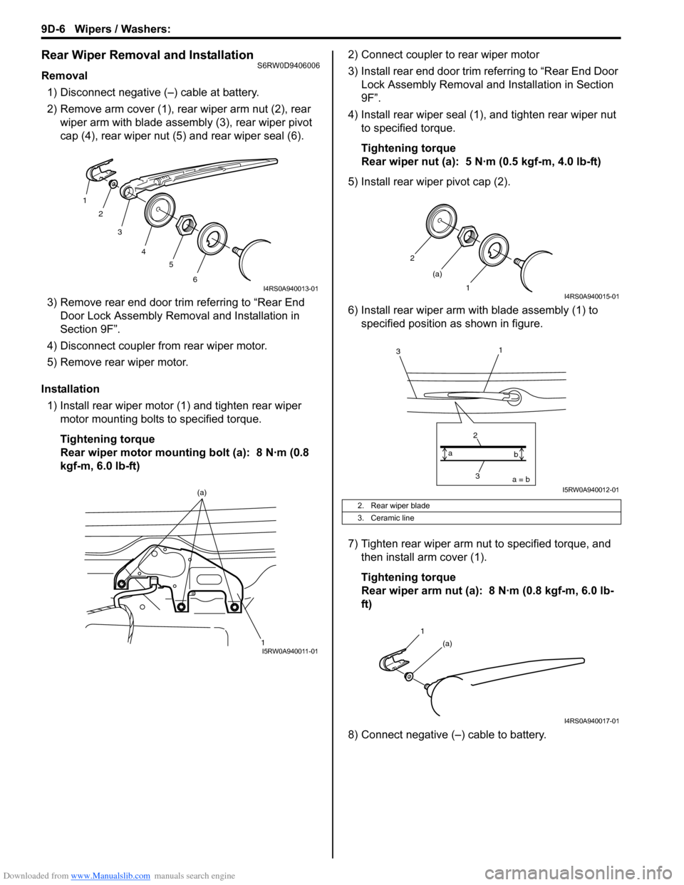
2) Remove arm cover (1), rear wiper arm nut (2), rear
wiper arm with blade assembly (3), rear wiper pivot
cap (4), rear wiper nut (5) and rear wiper seal (6).
3) Remove rear end door trim referring to “Rear End
Door Lock Assembly Removal and Installation in
Section 9F”.
4) Disconnect coupler from rear wiper motor.
5) Remove rear wiper motor.
Installation
1) Install rear wiper motor (1) and tighten rear wiper
motor mounting bolts to specified torque.
Tightening torque
Rear wiper motor mounting bolt (a): 8 N·m (0.8
kgf-m, 6.0 lb-ft)2) Connect coupler to rear wiper motor
3) Install rear end door trim referring to “Rear End Door
Lock Assembly Removal and Installation in Section
9F”.
4) Install rear wiper seal (1), and tighten rear wiper nut
to specified torque.
Tightening torque
Rear wiper nut (a): 5 N·m (0.5 kgf-m, 4.0 lb-ft)
5) Install rear wiper pivot cap (2).
6) Install rear wiper arm with blade assembly (1) to
specified position as shown in figure.
7) Tighten rear wiper arm nut to specified torque, and
then install arm cover (1).
Tightening torque
Rear wiper arm nut (a): 8 N·m (0.8 kgf-m, 6.0 lb-
ft)
8) Connect negative (–) cable to battery.
1
2
3
4
5
6
I4RS0A940013-01
1 (a)I5RW0A940011-01
2. Rear wiper blade
3. Ceramic line
2
1 (a)
I4RS0A940015-01
3 2a = b a
b
1
3
I5RW0A940012-01
1
(a)
I4RS0A940017-01
Page 1382 of 1556
Downloaded from www.Manualslib.com manuals search engine 9D-8 Wipers / Washers:
Windshield Wiper and Washer Switch Removal
and Installation
S6RW0D9406008
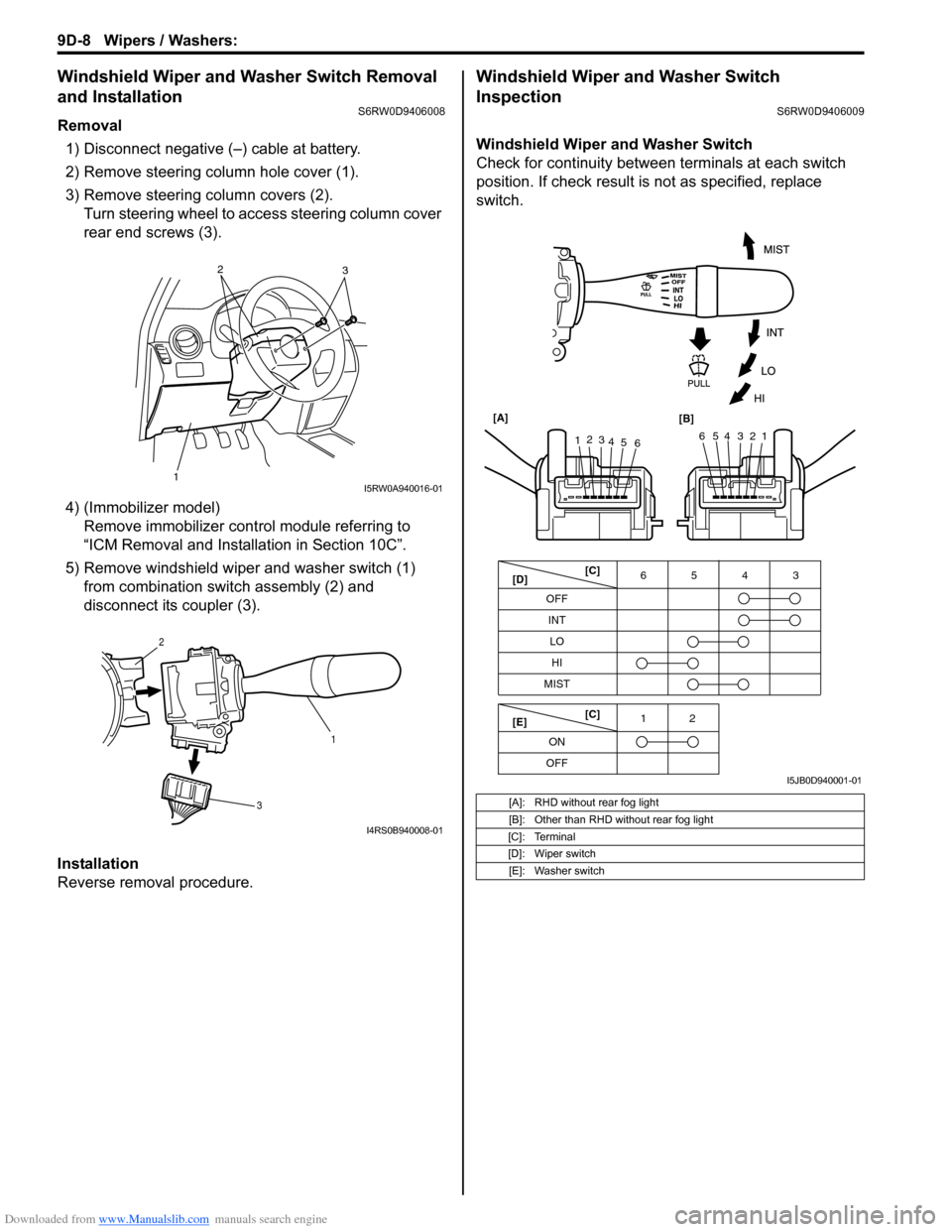
Removal
1) Disconnect negative (–) cable at battery.
2) Remove steering column hole cover (1).
3) Remove steering column covers (2).
Turn steering wheel to access steering column cover
rear end screws (3).
4) (Immobilizer model)
Remove immobilizer control module referring to
“ICM Removal and Installation in Section 10C”.
5) Remove windshield wiper and washer switch (1)
from combination switch assembly (2) and
disconnect its coupler (3).
Installation
Reverse removal procedure.
Windshield Wiper and Washer Switch
Inspection
S6RW0D9406009
Windshield Wiper and Washer Switch
Check for continuity between terminals at each switch
position. If check result is not as specified, replace
switch.
12
3I5RW0A940016-01
1 2
3
I4RS0B940008-01
[A]: RHD without rear fog light
[B]: Other than RHD without rear fog light
[C]: Terminal
[D]: Wiper switch
[E]: Washer switch
OFF
INT6543
MIST
OFF12
ONLO
HI
65432112
3
4
5
6 [A]
[B]
[C]
[D]
[E][C]
I5JB0D940001-01
Page 1384 of 1556
Downloaded from www.Manualslib.com manuals search engine 9D-10 Wipers / Washers:
Rear Wiper and Washer Switch Removal and
Installation
S6RW0D9406010
For removal and installation, refer to “Windshield Wiper
and Washer Switch Removal and Installation”.
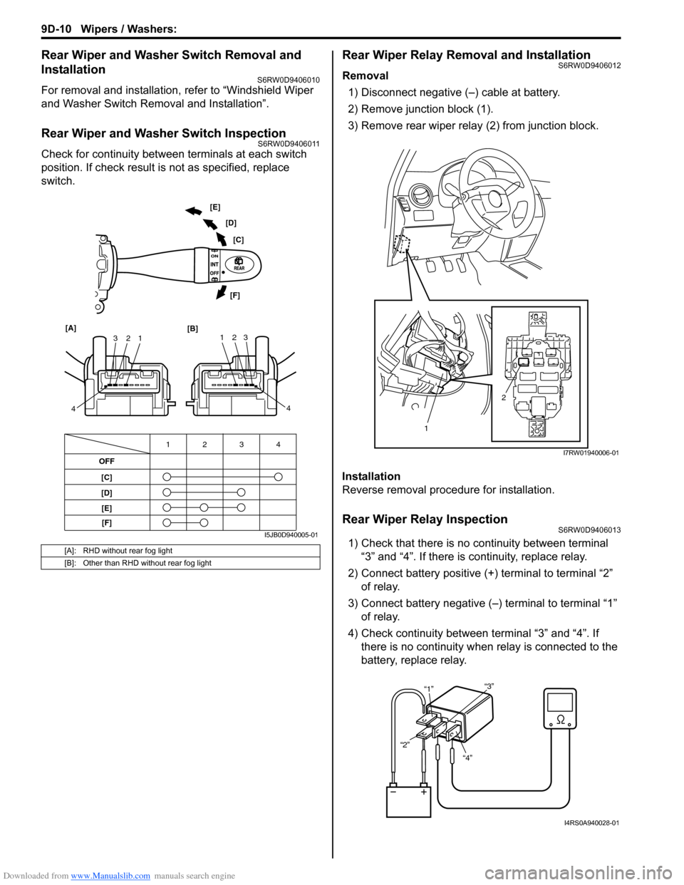
Rear Wiper and Washer Switch InspectionS6RW0D9406011
Check for continuity between terminals at each switch
position. If check result is not as specified, replace
switch.
Rear Wiper Relay Removal and InstallationS6RW0D9406012
Removal
1) Disconnect negative (–) cable at battery.
2) Remove junction block (1).
3) Remove rear wiper relay (2) from junction block.
Installation
Reverse removal procedure for installation.
Rear Wiper Relay InspectionS6RW0D9406013
1) Check that there is no continuity between terminal
“3” and “4”. If there is continuity, replace relay.
2) Connect battery positive (+) terminal to terminal “2”
of relay.
3) Connect battery negative (–) terminal to terminal “1”
of relay.
4) Check continuity between terminal “3” and “4”. If
there is no continuity when relay is connected to the
battery, replace relay.[A]: RHD without rear fog light
[B]: Other than RHD without rear fog light
OFF
[C]
[D]4 3 12
1 2 3
4 [A]
[B]123
4 [C] [D] [E]
[F]
[E]
[F]
I5JB0D940005-01
2
1
I7RW01940006-01
“4” “2”“1”“3”
I4RS0A940028-01
Page 1404 of 1556
Downloaded from www.Manualslib.com manuals search engine 9E-19 Glass / Windows / Mirrors:
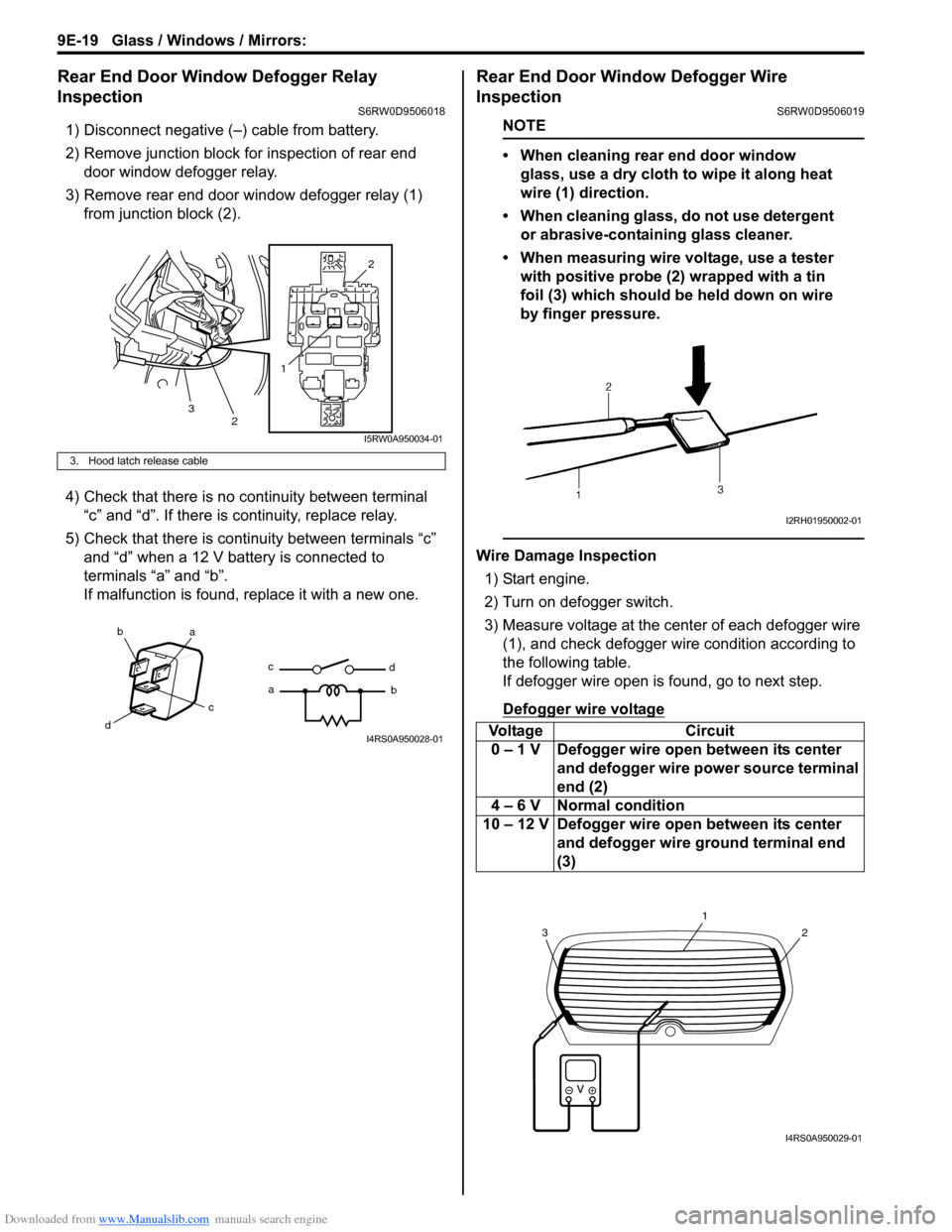
Rear End Door Window Defogger Relay
Inspection
S6RW0D9506018
1) Disconnect negative (–) cable from battery.
2) Remove junction block for inspection of rear end
door window defogger relay.
3) Remove rear end door window defogger relay (1)
from junction block (2).
4) Check that there is no continuity between terminal
“c” and “d”. If there is continuity, replace relay.
5) Check that there is continuity between terminals “c”
and “d” when a 12 V battery is connected to
terminals “a” and “b”.
If malfunction is found, replace it with a new one.
Rear End Door Window Defogger Wire
Inspection
S6RW0D9506019
NOTE
• When cleaning rear end door window
glass, use a dry cloth to wipe it along heat
wire (1) direction.
• When cleaning glass, do not use detergent
or abrasive-containing glass cleaner.
• When measuring wire voltage, use a tester
with positive probe (2) wrapped with a tin
foil (3) which should be held down on wire
by finger pressure.
Wire Damage Inspection
1) Start engine.
2) Turn on defogger switch.
3) Measure voltage at the center of each defogger wire
(1), and check defogger wire condition according to
the following table.
If defogger wire open is found, go to next step.
Defogger wire voltage
3. Hood latch release cable
12
2
3
I5RW0A950034-01
ba
c
dc
ad
bI4RS0A950028-01Voltage Circuit
0 – 1 V Defogger wire open between its center
and defogger wire power source terminal
end (2)
4 – 6 V Normal condition
10 – 12 V Defogger wire open between its center
and defogger wire ground terminal end
(3)
I2RH01950002-01
2
1
3
I4RS0A950029-01
Page 1414 of 1556
Downloaded from www.Manualslib.com manuals search engine 9F-3 Security and Locks:
Diagnostic Information and Procedures
Power Door Lock System Symptom Diagnosis (If Equipped)S6RW0D9604001
NOTE
• Use of SUZUKI scan tool makes it easy to check whether a faulty condition is on the input side or
output side of BCM. For checking procedure, refer to “Diagnosis Using Output Test Function of
SUZUKI Scan Tool” under “Scan Tool Data in Section 10B”.
• Check each part in the order from the top of the following list.
Power Door Lock System Operation Inspection (If Equipped)S6RW0D9604002
1) Check the following operation:
a) Turn the driver side key cylinder is turned LOCK once, check all doors lock.
b) Turn the driver side door key cylinder is turned UNLOCK position with door key twice, check all doors unlock.
c) With all doors unlocked, insert key in key cylinder of driver side door and turn it to lock side, turn it again to lock
side within 3 seconds and check that no door can be opened even when door lock knob is moved to unlock
side (dead lock function, if equipped).
If malfunction is found, go to “Power Door Lock System Symptom Diagnosis (If Equipped)”. Condition Possible cause Correction / Reference Item
All door can not be locked
/ unlocked by all of
switchesCircuit fuse blownReplace fuse and check for short circuit.
Wiring or grounding faultyRepair circuit.
BCM faultyReplace after making sure that none of above
parts is faulty.
All door can not be locked
/ unlocked by only power
door lock switchCircuit fuse blownReplace fuse and check for short circuit.
Power door lock switch faultyCheck power door lock switch referring to
“Power Door Lock Switch Inspection (If
Equipped)”.
Wiring harness connected to power door
lock switch faultyRepair.
Wiring or grounding faultyRepair circuit.
BCM faultyReplace after making sure that none of above
parts is faulty.
All door can not be locked
/ unlocked by only key
cylinder switchCircuit fuse blownReplace fuse and check for short circuit.
Key cylinder switch faultyCheck key cylinder switch referring to “Door
Key Cylinder Switch Inspection (If Equipped)”.
Wiring or grounding faultyRepair circuit.
BCM faultyReplace after making sure that none of above
parts is faulty.
Only one door can not be
locked / unlockedPower door lock actuator faultyCheck actuator referring to “Power Door Lock
Actuator Inspection (If Equipped)”.
Wiring harness connected to applicable
door lock actuator faultyRepair.
BCM faultyReplace after making sure that none of above
parts is faulty.