2006 SUZUKI SX4 wheel
[x] Cancel search: wheelPage 1366 of 1556
Downloaded from www.Manualslib.com manuals search engine 9C-14 Instrumentation / Driver Info. / Horn:
Repair Instructions
Ignition Switch Removal and InstallationS6RW0D9306001
Removal
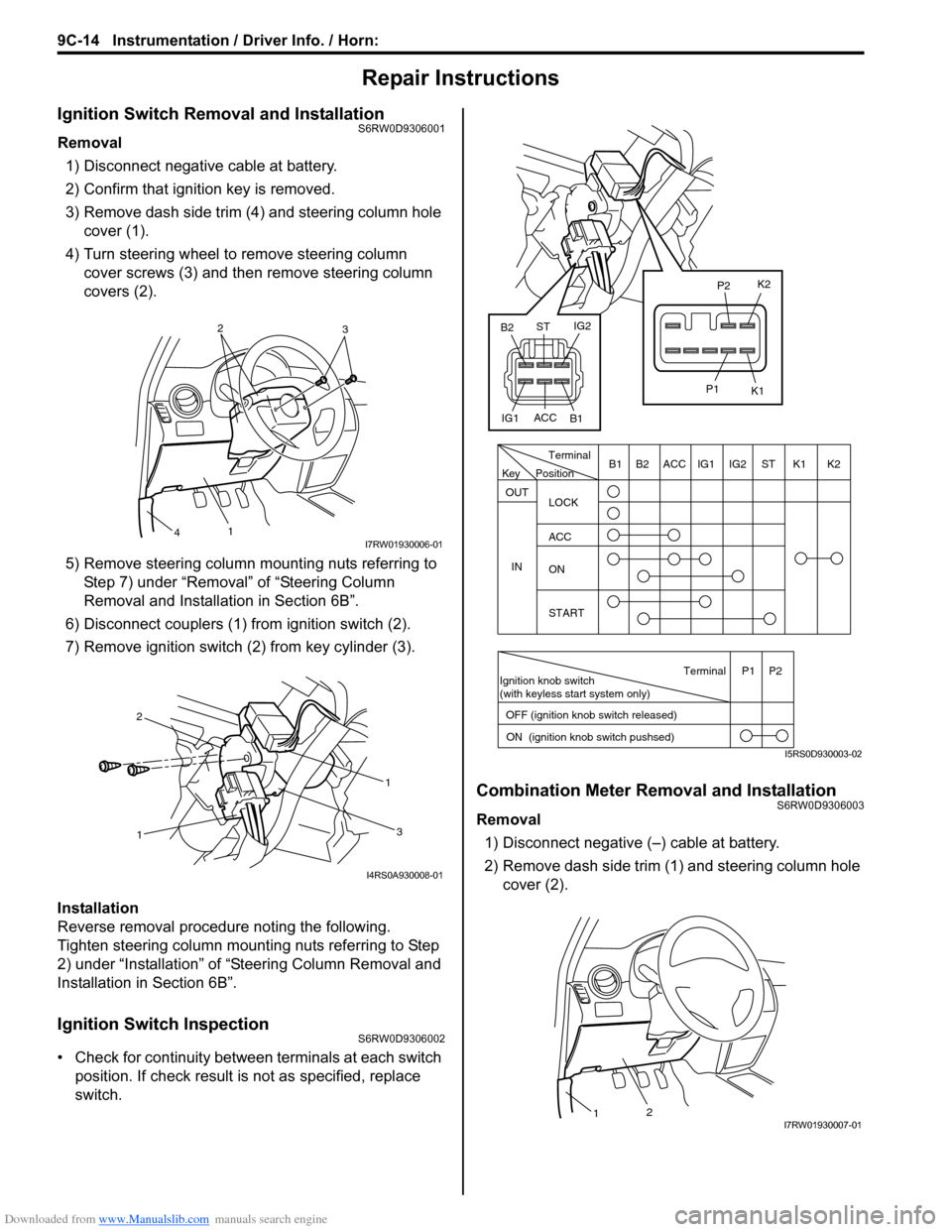
1) Disconnect negative cable at battery.
2) Confirm that ignition key is removed.
3) Remove dash side trim (4) and steering column hole
cover (1).
4) Turn steering wheel to remove steering column
cover screws (3) and then remove steering column
covers (2).
5) Remove steering column mounting nuts referring to
Step 7) under “Removal” of “Steering Column
Removal and Installation in Section 6B”.
6) Disconnect couplers (1) from ignition switch (2).
7) Remove ignition switch (2) from key cylinder (3).
Installation
Reverse removal procedure noting the following.
Tighten steering column mounting nuts referring to Step
2) under “Installation” of “Steering Column Removal and
Installation in Section 6B”.
Ignition Switch InspectionS6RW0D9306002
• Check for continuity between terminals at each switch
position. If check result is not as specified, replace
switch.
Combination Meter Removal and InstallationS6RW0D9306003
Removal
1) Disconnect negative (–) cable at battery.
2) Remove dash side trim (1) and steering column hole
cover (2).
2
3
1
4I7RW01930006-01
11
2
3
I4RS0A930008-01
PositionTerminal
LOCK
ACC
ON
START OUT
INK2 K1 ST IG2 IG1 ACC B1 B2
Ignition knob switch
(with keyless start system only)
ACC
IG1IG2
ST
B2
B1K2
K1
P2
P1
Terminal
OFF (ignition knob switch released)
ON (ignition knob switch pushsed)P1 P2
Key
I5RS0D930003-02
21I7RW01930007-01
Page 1369 of 1556
Downloaded from www.Manualslib.com manuals search engine Instrumentation / Driver Info. / Horn: 9C-17
Outside Air Temperature Sensor Removal and
Installation (If Equipped)
S6RW0D9306013
Removal
1) Disconnect negative (–) cable at battery.
2) Remove front bumper referring to “Front Bumper
and Rear Bumper Components in Section 9K”.
3) Disconnect connector from outside air temperature
sensor.
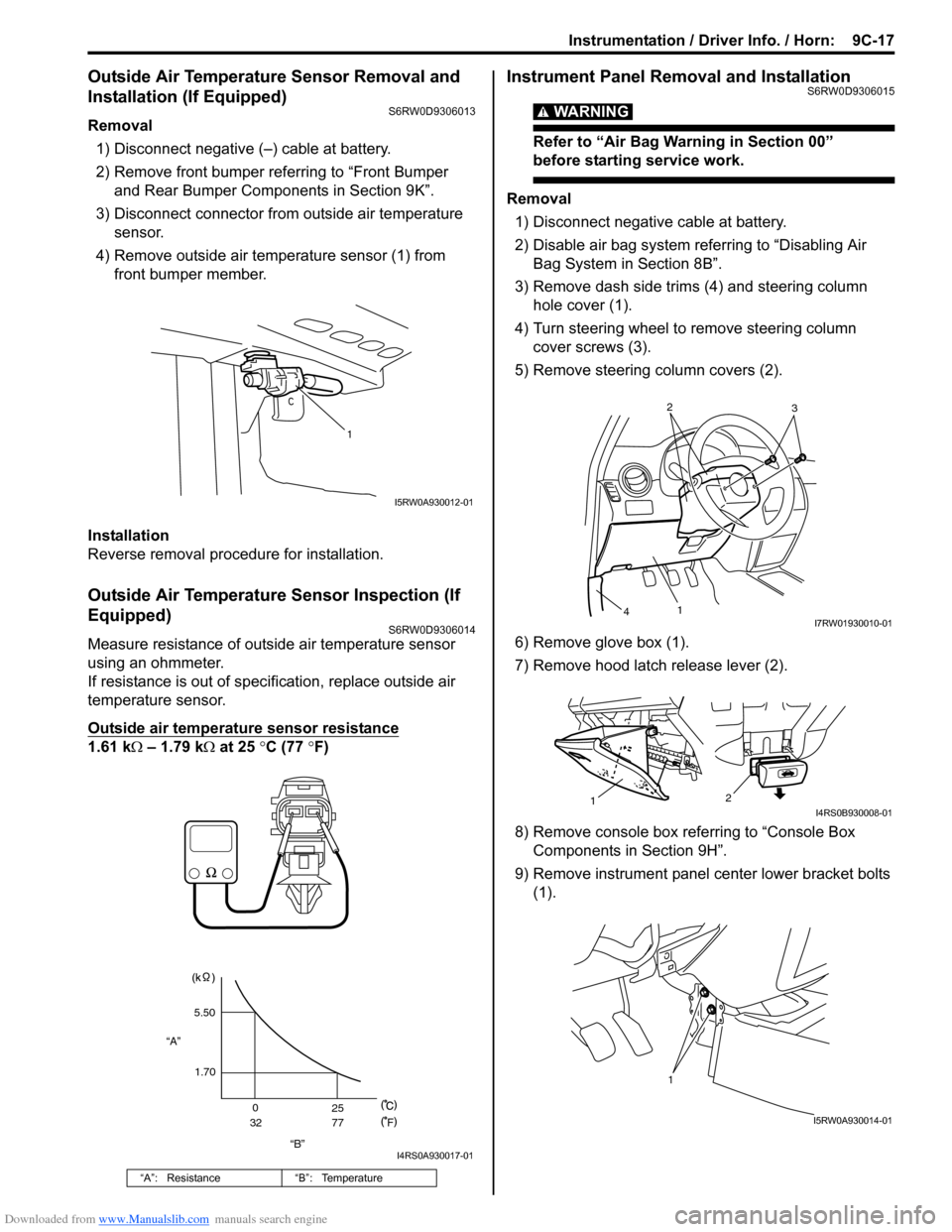
4) Remove outside air temperature sensor (1) from
front bumper member.
Installation
Reverse removal procedure for installation.
Outside Air Temperature Sensor Inspection (If
Equipped)
S6RW0D9306014
Measure resistance of outside air temperature sensor
using an ohmmeter.
If resistance is out of specification, replace outside air
temperature sensor.
Outside air temperature sensor resistance
1.61 kΩ – 1.79 kΩ at 25 °C (77 °F)
Instrument Panel Removal and InstallationS6RW0D9306015
WARNING!
Refer to “Air Bag Warning in Section 00”
before starting service work.
Removal
1) Disconnect negative cable at battery.
2) Disable air bag system referring to “Disabling Air
Bag System in Section 8B”.
3) Remove dash side trims (4) and steering column
hole cover (1).
4) Turn steering wheel to remove steering column
cover screws (3).
5) Remove steering column covers (2).
6) Remove glove box (1).
7) Remove hood latch release lever (2).
8) Remove console box referring to “Console Box
Components in Section 9H”.
9) Remove instrument panel center lower bracket bolts
(1).
“A”: Resistance “B”: Temperature
1
I5RW0A930012-01
“B” “A”5.50
1.70
0
3225
77
F
I4RS0A930017-01
2
3
1
4I7RW01930010-01
2
1I4RS0B930008-01
1
I5RW0A930014-01
Page 1373 of 1556
Downloaded from www.Manualslib.com manuals search engine Instrumentation / Driver Info. / Horn: 9C-21
Antenna Base Removal and InstallationS6RW0D9306023
Removal
1) Remove head lining referring to “Head Lining
Removal and Installation in Section 9H”.
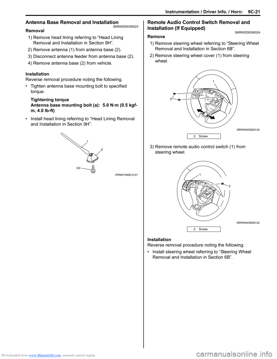
2) Remove antenna (1) from antenna base (2).
3) Disconnect antenna feeder from antenna base (2).
4) Remove antenna base (2) from vehicle.
Installation
Reverse removal procedure noting the following.
• Tighten antenna base mounting bolt to specified
torque.
Tightening torque
Antenna base mounting bolt (a): 5.0 N·m (0.5 kgf-
m, 4.0 lb-ft)
• Install head lining referring to “Head Lining Removal
and Installation in Section 9H”.
Remote Audio Control Switch Removal and
Installation (If Equipped)
S6RW0D9306024
Remove
1) Remove steering wheel referring to “Steering Wheel
Removal and Installation in Section 6B”.
2) Remove steering wheel cover (1) from steering
wheel.
3) Remove remote audio control switch (1) from
steering wheel.
Installation
Reverse removal procedure noting the following.
• Install steering wheel referring to “Steering Wheel
Removal and Installation in Section 6B”.
(a)1
2
I7RW01930012-01
2. Screw
2. Screw
2
1
I5RW0A930025-02
1
2
I5RW0A930026-02
Page 1382 of 1556
Downloaded from www.Manualslib.com manuals search engine 9D-8 Wipers / Washers:
Windshield Wiper and Washer Switch Removal
and Installation
S6RW0D9406008
Removal
1) Disconnect negative (–) cable at battery.
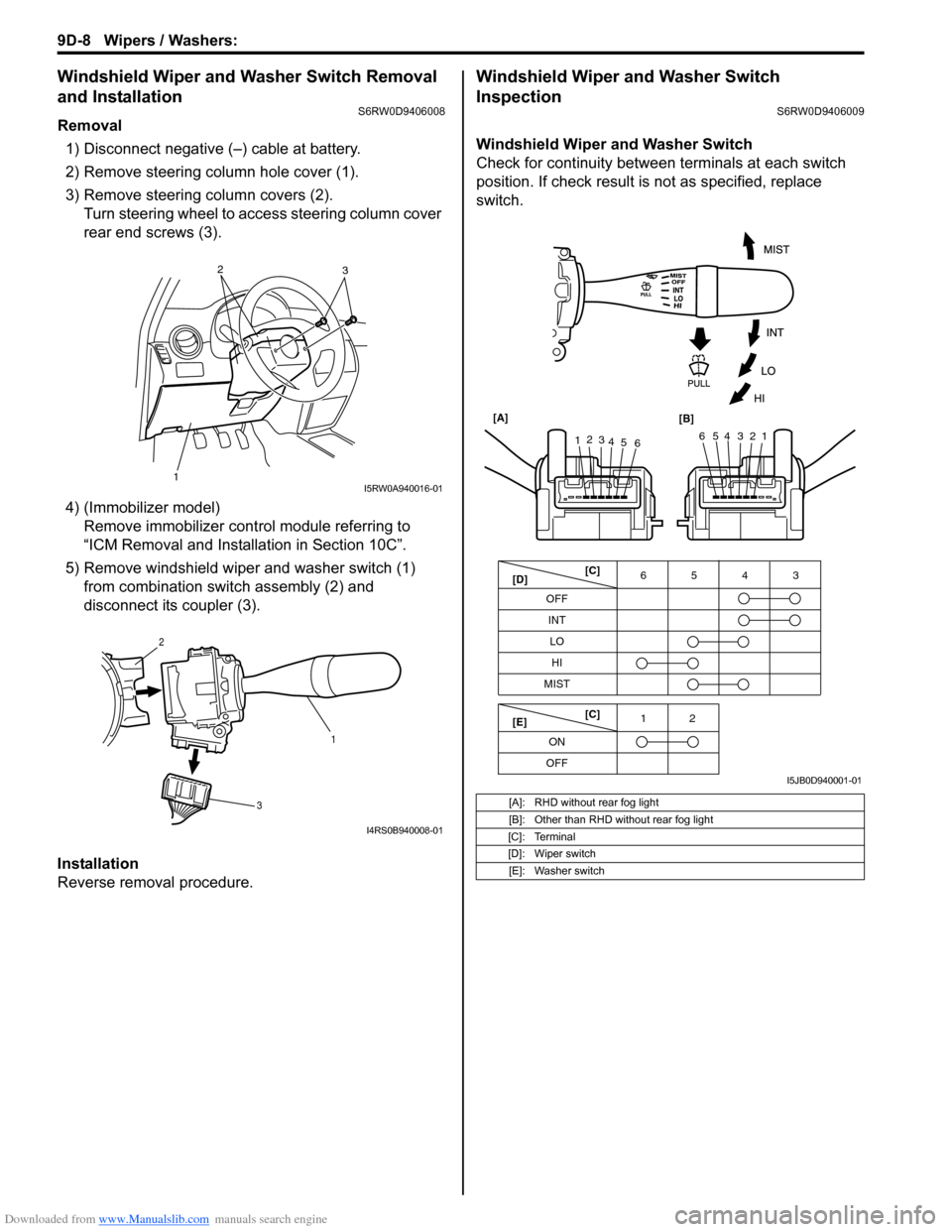
2) Remove steering column hole cover (1).
3) Remove steering column covers (2).
Turn steering wheel to access steering column cover
rear end screws (3).
4) (Immobilizer model)
Remove immobilizer control module referring to
“ICM Removal and Installation in Section 10C”.
5) Remove windshield wiper and washer switch (1)
from combination switch assembly (2) and
disconnect its coupler (3).
Installation
Reverse removal procedure.
Windshield Wiper and Washer Switch
Inspection
S6RW0D9406009
Windshield Wiper and Washer Switch
Check for continuity between terminals at each switch
position. If check result is not as specified, replace
switch.
12
3I5RW0A940016-01
1 2
3
I4RS0B940008-01
[A]: RHD without rear fog light
[B]: Other than RHD without rear fog light
[C]: Terminal
[D]: Wiper switch
[E]: Washer switch
OFF
INT6543
MIST
OFF12
ONLO
HI
65432112
3
4
5
6 [A]
[B]
[C]
[D]
[E][C]
I5JB0D940001-01
Page 1455 of 1556
Downloaded from www.Manualslib.com manuals search engine Paint / Coatings: 9L-1
Body, Cab and Accessories
Paint / Coatings
General Description
Anti-Corrosion Treatment ConstructionS6RW0D9C01001
WARNING!
Standard shop practices, particularly eye protection, should be followed during the performance of the
following operations to avoid personal injury.
As rust proof treatment, steel sheets are given corrosion resistance on the interior and/or exterior.
These corrosion resistance steel sheet materials are called one of two-side galvanized steel sheets.
It is for the sake of rust protection that these materials are selected and given a variety of treatments as described
blow.
• Steel sheets are treated with cathodic electro primer which is excellent in corrosion resistance.
• Rust proof wax coatings are applied to door and side sill insides where moisture is liable to stay.
• Vinyl coating is applied to body underside and wheel housing inside.
• Sealer is applied to door hem, engine compartment steel sheet-to-steel sheet joint, and the like portions to prevent
water penetration and resulting in rust occurrence.
In panel replacement or collision damage repair, leaving the relevant area untreated as it is in any operation which
does disturb the rust proof treatment will cause corrosion to that area. Therefore, it is the essential function of any
repair operation to correctly recoat the related surfaces of the relevant area.
All the metal panels are coated with metal conditioners and primer coating during vehicle production. Following the
repair and/or replacement parts installation, every accessible bare metal surface should be cleaned and coated with
rust proof primer. Perform this operation prior to the application of sealer and rust proof wax coating.
Sealer is applied to the specific joints of a vehicle during production. The sealer is intended to prevent dust from
entering the vehicle and serves also as an anticorrosion barrier. The sealer is applied to the door and hood hem areas
and between panels. Correct and reseal the originally sealed joints if damaged. Reseal the attaching joints of a new
replacement panel and reseal the hem area of a replacement door or hood.
Use a quality sealer to seal the flanged joints, overlap joints and seams. The sealer must have flexible characteristics
and paint ability after it’s applied to repair areas.
For the sealer to fill open joints, use caulking material. Select a sealer in conformance with the place and purpose of a
specific use. Observe the manufacturer’s label-stand instructions when using the sealer.
In many cases, repaired places require color painting. When this is required, follow the ordinary techniques specified
for the finish preparation, color painting and undercoating build-up.
Rust proof wax, a penetrative compound, is applied to the metal-to-metal surfaces (door and side sill insides) where it
is difficult to use ordinary undercoating material for coating. Therefore, when selecting the rust proof wax, it may be the
penetrative type.
During the undercoating (vinyl coating) application, care should be taken that sealer is not applied to the engine-
related parts and shock absorber mounting or rotating parts. Following the under coating, make sure that body drain
holes are kept open.
The sequence of the application steps of the anti-corrosion materials are as follows:
1) Clean and prepare the metal surface.
2) Apply primer.
3) Apply sealer (all joints sealed originally).
4) Apply color in areas where color is required such as hem flanges, exposed joints and under body components.
5) Apply anticorrosion compound (penetrative wax).
6) Apply undercoating (rust proof material).
Page 1521 of 1556
Downloaded from www.Manualslib.com manuals search engine Immobilizer Control System: 10C-19
Repair Instructions
ICM Removal and InstallationS6RW0DA306001
Removal
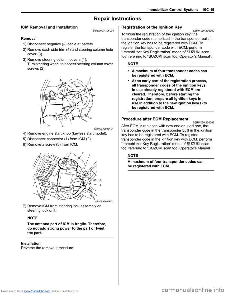
1) Disconnect negative (–) cable at battery.
2) Remove dash side trim (4) and steering column hole
cover (3).
3) Remove steering column covers (1).
Turn steering wheel to access steering column cover
screws (2).
4) Remove engine start knob (keyless start model).
5) Disconnect connector (1) from ICM (2).
6) Remove a screw (3) from ICM.
7) Remove ICM from steering lock assembly or
steering lock unit.
NOTE
The antenna part of ICM is fragile. Therefore,
do not add strong power to the part or twist
the part.
Installation
Reverse the removal procedure.
Registration of the Ignition KeyS6RW0DA306002
To finish the registration of the ignition key, the
transponder code memorized in the transponder built in
the ignition key has to be registered with ECM. To
register the transponder code with ECM, perform
“Immobilizer Key Registration” mode of SUZUKI scan
tool referring to “SUZUKI scan tool Operator’s Manual”.
NOTE
• A maximum of four transponder codes can
be registered with ECM.
• At an early part of the registration process,
all transponder codes of the ignition keys
in use already registered with ECM are
cleared. Therefore, before starting the
registration, prepare all ignition keys in
use in addition to the new ignition key(s) to
be registered with ECM.
Procedure after ECM ReplacementS6RW0DA306003
After ECM is replaced with new one or used one, the
transponder code in the transponder built in the ignition
key has to be registered with ECM. To register
transponder code in the ignition key with ECM, perform
“Immobilizer Key Registration” mode of SUZUKI scan
tool referring to “SUZUKI scan tool Operator’s Manual”.
NOTE
A maximum of four transponder codes can
be registered with ECM.
1
2
3
4I6RW0BA30004-01
2
3
1
I4RS0BA30007-03