2006 SUZUKI SX4 ECU Wiring diagram
[x] Cancel search: ECU Wiring diagramPage 190 of 1556

Downloaded from www.Manualslib.com manuals search engine 1A-140 Engine General Information and Diagnosis:
DTC Troubleshooting
NOTE
Before this troubleshooting is performed, read the precautions for DTC troubleshooting referring to
“Precautions for DTC Troubleshooting”.
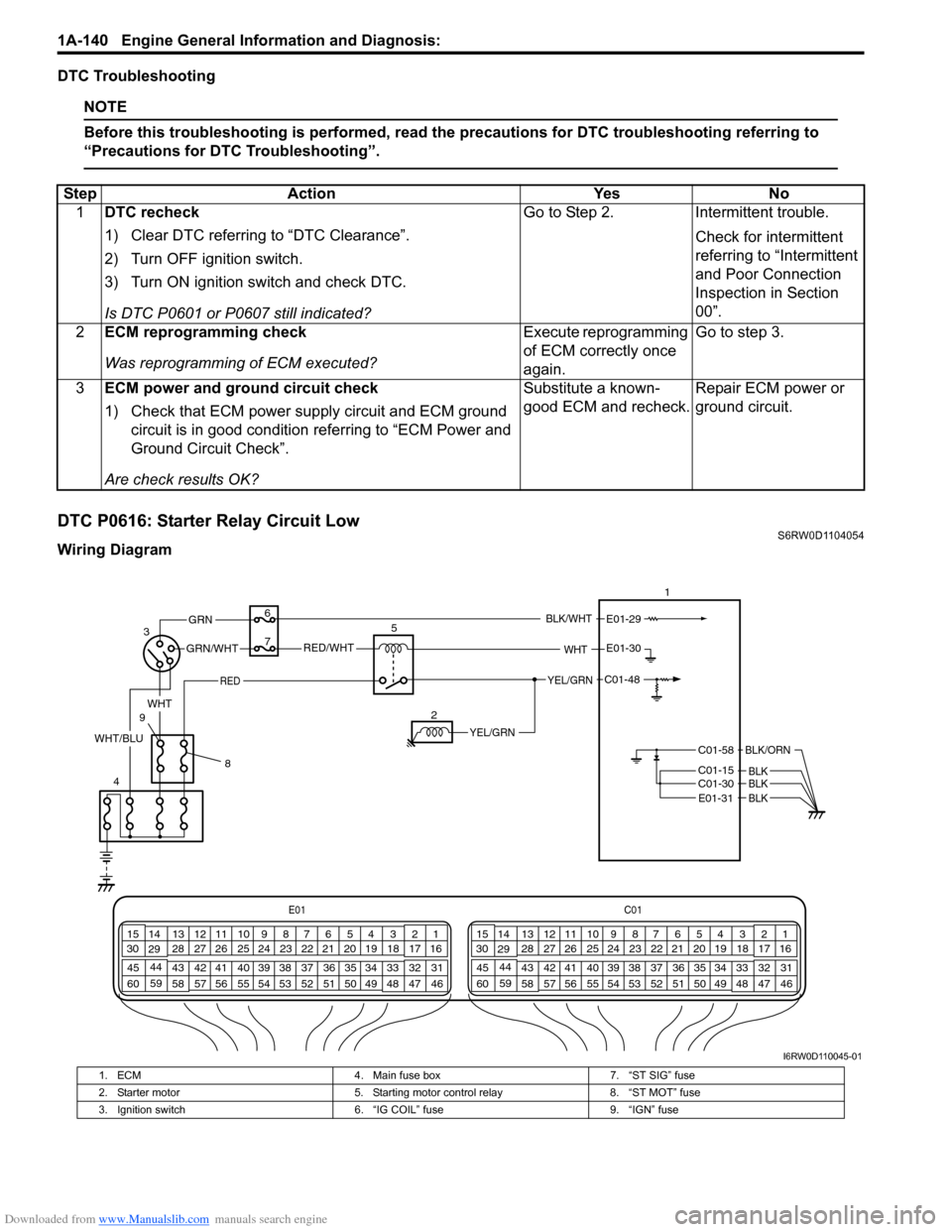
DTC P0616: Starter Relay Circuit LowS6RW0D1104054
Wiring DiagramStep Action Yes No
1DTC recheck
1) Clear DTC referring to “DTC Clearance”.
2) Turn OFF ignition switch.
3) Turn ON ignition switch and check DTC.
Is DTC P0601 or P0607 still indicated?Go to Step 2. Intermittent trouble.
Check for intermittent
referring to “Intermittent
and Poor Connection
Inspection in Section
00”.
2ECM reprogramming check
Was reprogramming of ECM executed?Execute reprogramming
of ECM correctly once
again.Go to step 3.
3ECM power and ground circuit check
1) Check that ECM power supply circuit and ECM ground
circuit is in good condition referring to “ECM Power and
Ground Circuit Check”.
Are check results OK?Substitute a known-
good ECM and recheck.Repair ECM power or
ground circuit.
E01C01
3 4
18 19 5 6 7 10 11
17 20
47 46 49 50 51 21 22
5216 259
24 14
29
55 57 54 53 59
60 582
26 27 28 15
30
56 4832 31 34 35 36 37 40 42 39 38 44
45 43 41 331 12 13
238 3 4
18 19 5 6 7 10 11
17 20
47 46 49 50 51 21 22
5216 259
24 14
29
55 57 54 53 59
60 582
26 27 28 15
30
56 4832 31 34 35 36 37 40 42 39 38 44
45 43 41 331 12 13
238
3
461E01-29
C01-58
C01-15 C01-30
BLK/ORN
BLKBLK
5
RED/WHTGRN/WHT
GRN
RED
E01-30
C01-48
BLK/WHT
YEL/GRN
YEL/GRN
WHT
2 7
8 9WHT
WHT/BLU
BLKE01-31
I6RW0D110045-01
1. ECM 4. Main fuse box 7. “ST SIG” fuse
2. Starter motor 5. Starting motor control relay 8. “ST MOT” fuse
3. Ignition switch 6. “IG COIL” fuse 9. “IGN” fuse
Page 626 of 1556

Downloaded from www.Manualslib.com manuals search engine 4E-21 ABS:
DTC C1015: G Sensor Circuit (4WD Model)S6RW0D4504013
Wiring Diagram
Refer to “Wiring Diagram” under “DTC C1013: Control Module Mismatch”.
DTC Detecting Condition and Trouble Area
NOTE
When a vehicle is lifted up and its wheel(s) is turned, this DTC is set.
In such case, clear the DTC and check again.
Troubleshooting DTC Detecting Condition Trouble Area
• G sensor signal voltage is out of specified range.
• Vehicle behavior and G sensor signal is disagreed.• G sensor
• G sensor circuit
• ABS control module
Step Action Yes No
1Was “ABS Check” performed?Go to Step 2. Go to “ABS Check”.
2Is G sensor installed its bracket securely?Go to Step 3. Tighten G sensor bolt
and recheck.
3G sensor check
1) Disconnect G sensor connector and ABS hydraulic unit /
control module connector with ignition switch turned
OFF.
2) Check for proper connection to G sensor connector and
ABS hydraulic unit / control module terminals of “E08-3”
and “E08-6”.
3) If OK then check G sensor referring to “G Sensor
Inspection (4WD Model)”.
Is it in good condition?Go to Step 4. Replace G sensor.
4G sensor power source voltage check
1) Turn ignition switch to ON position and measure voltage
between “GRN/ORN terminal of G sensor connector and
vehicle body ground.
Is it 10 – 14 V?Go to Step 5. “GRN/ORN” circuit
open.
5G sensor signal circuit and ground circuit check
1) Measure resistance between following terminals.
• Between “E08-3” terminal and “GRN/BLK” terminal of
G sensor.
• Between “E08-6” terminal and “GRN/YEL” terminal of
G sensor.
Is each resistance less than 2
Ω?Go to Step 6. “GRN/BLK” and/or
“GRN/YEL” wire circuits
in open or high
resistance.
6G sensor ground circuit check
1) Connect ABS hydraulic unit / control module connector
with ignition switch turned OFF.
2) Turn ignition switch to ON position and measure voltage
between “GRN/BLK” terminal of G sensor connector and
vehicle body ground.
Is it 0 V?Substitute a known-
good ABS hydraulic unit
/ control module
assembly and recheck.“GRN/BLK” circuit to
power circuit.
Page 1124 of 1556

Downloaded from www.Manualslib.com manuals search engine 8B-85 Air Bag System:
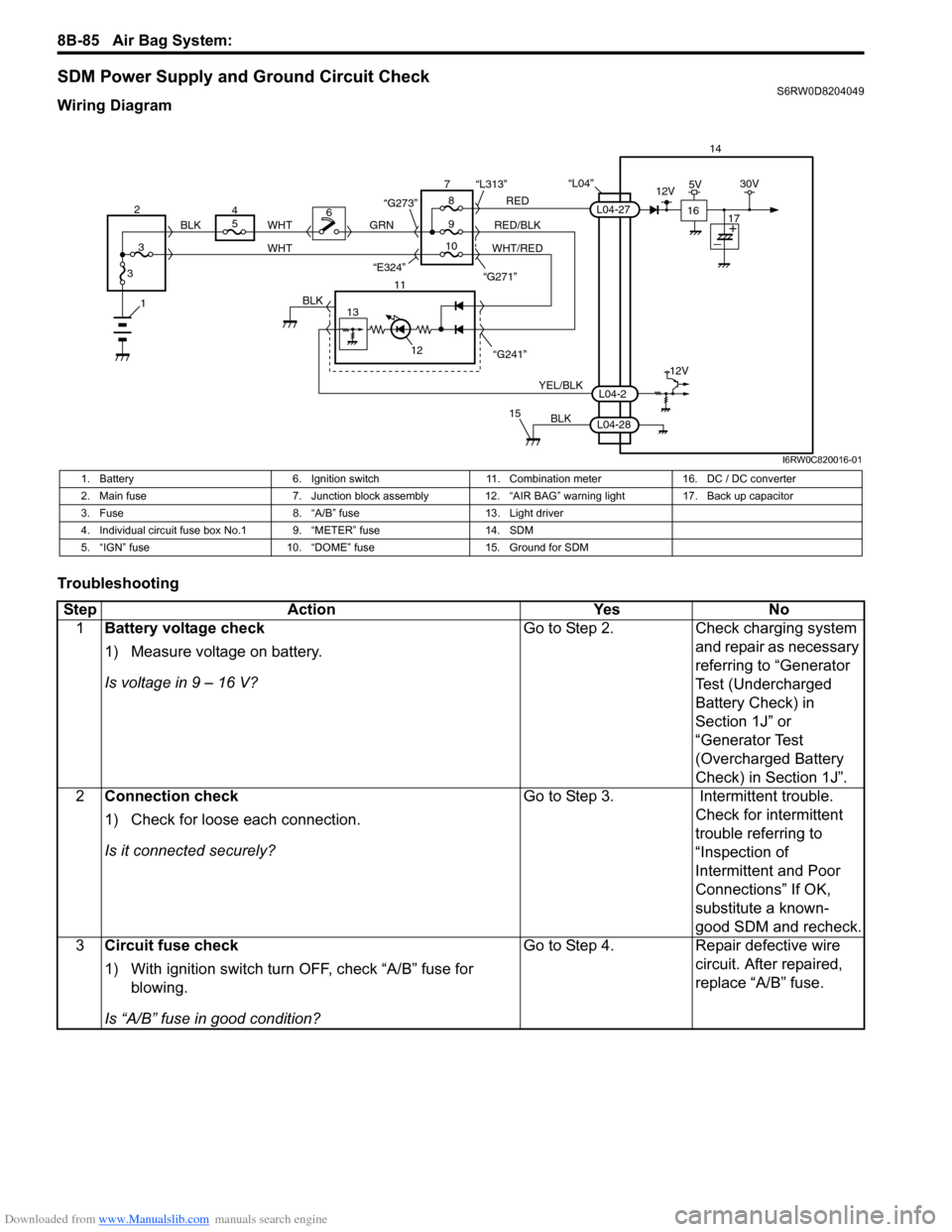
SDM Power Supply and Ground Circuit CheckS6RW0D8204049
Wiring Diagram
Troubleshooting
“L04”14
5
9RED
RED/BLK GRN
YEL/BLK
BLK
8 7
11
12
15
L04-2
L04-28
L04-27
“G241” “G271” “L313”
13
12V
6
1BLK
WHT WHT
WHT/RED 2
34
310 BLK
“G273”
“E324”16
12V5V30V
17
I6RW0C820016-01
1. Battery 6. Ignition switch 11. Combination meter 16. DC / DC converter
2. Main fuse 7. Junction block assembly 12. “AIR BAG” warning light 17. Back up capacitor
3. Fuse 8. “A/B” fuse 13. Light driver
4. Individual circuit fuse box No.1 9. “METER” fuse 14. SDM
5. “IGN” fuse 10. “DOME” fuse 15. Ground for SDM
Step Action Yes No
1Battery voltage check
1) Measure voltage on battery.
Is voltage in 9 – 16 V?Go to Step 2. Check charging system
and repair as necessary
referring to “Generator
Test (Undercharged
Battery Check) in
Section 1J” or
“Generator Test
(Overcharged Battery
Check) in Section 1J”.
2Connection check
1) Check for loose each connection.
Is it connected securely?Go to Step 3. Intermittent trouble.
Check for intermittent
trouble referring to
“Inspection of
Intermittent and Poor
Connections” If OK,
substitute a known-
good SDM and recheck.
3Circuit fuse check
1) With ignition switch turn OFF, check “A/B” fuse for
blowing.
Is “A/B” fuse in good condition?Go to Step 4. Repair defective wire
circuit. After repaired,
replace “A/B” fuse.
Page 1471 of 1556

Downloaded from www.Manualslib.com manuals search engine Table of Contents 10- i
10
Section 10
CONTENTS
Control Systems
Precautions ............................................... 10-1
Precautions........................................................... 10-1
Precautions for Control Systems......................... 10-1
Body Electrical Control System ........... 10B-1
Precautions......................................................... 10B-1
Precautions in Diagnosing Trouble ................... 10B-1
General Description ........................................... 10B-1
BCM General Description ................................. 10B-1
CAN Communication System Description......... 10B-1
Theft Deterrent Light ......................................... 10B-2
Security Alarm Description (If Equipped) .......... 10B-2
Schematic and Routing Diagram ...................... 10B-3
Body Electrical Control System Wiring Circuit
Diagram .......................................................... 10B-3
Connector Layout Diagram of BCM and
Junction Block ................................................. 10B-6
Component Location ......................................... 10B-7
BCM and Related System Component
Location .......................................................... 10B-7
Diagnostic Information and Procedures .......... 10B-8
BCM Self-Diagnosis Function ........................... 10B-8
Body Electrical Control System Check.............. 10B-9
Scan Tool Data ............................................... 10B-11
DTC Table ....................................................... 10B-13
DTC Check ..................................................... 10B-14
DTC Clearance ............................................... 10B-15
BCM Power Circuit and Ground Circuit Check 10B-16
DTC B1133 (DTC No. 1133): Battery Voltage
Too High ....................................................... 10B-17
DTC B1141 / DTC B1142 (No. 1141 / No.
1142) Outside Air Temperature (Ambient
Temp.) Sensor Circuit Malfunction ................ 10B-18
DTC B1150 (No. 1150): Air Bag
Communication Circuit Malfunction .............. 10B-19
DTC B1157 (No. 1157) Air Bag Deployment
Signal Input ................................................... 10B-20
DTC B1170 (No. 1170): EEPROM Access
Error .............................................................. 10B-20
DTC U0073 (No. 0073): Control Module
Communication Bus Off ................................ 10B-20
DTC U0100 (No. 0100): Lost Communication
with ECM....................................................... 10B-20DTC U0101 (No. 0101): Lost Communication
with TCM ....................................................... 10B-20
DTC U0155 (No. 0155): Lost Communication
with Instrument Panel Cluster (IPC) Control
Module .......................................................... 10B-20
DTC U1144 (No. 1144): Lost Communication
with Keyless Start Control Module ................ 10B-20
Inspection of BCM and Its Circuits .................. 10B-21
Repair Instructions ..........................................10B-28
BCM (Included in Junction Block) Removal
and Installation .............................................. 10B-28
Security Alarm Mode Selection Procedure (If
Equipped) ...................................................... 10B-29
Outside Air Temperature Sensor Removal
and Installation .............................................. 10B-29
Outside Air Temperature Sensor Inspection ... 10B-29
Special Tools and Equipment .........................10B-29
Special Tool .................................................... 10B-29
Immobilizer Control System ................. 10C-1
Precautions.........................................................10C-1
Precautions in Diagnosing Troubles .................10C-1
Precaution in Replacing ECM ...........................10C-1
Precaution in Replacing Ignition Key ................10C-1
Precautions in Handling Immobilizer Control
System ............................................................10C-1
General Description ...........................................10C-2
Immobilizer Control System Introduction ..........10C-2
On-Board Diagnostic System Description
(Self-diagnosis Function)................................10C-2
Schematic and Routing Diagram ......................10C-3
Immobilizer Control System Wiring Circuit
Diagram...........................................................10C-3
Component Location .........................................10C-5
Immobilizer Control System Components
Location...........................................................10C-5
Diagnostic Information and Procedures ..........10C-5
Immobilizer Control System Check ...................10C-5
DTC Check........................................................10C-6
DTC Clearance .................................................10C-6
DTC Table .........................................................10C-7
Scan Tool Data .................................................10C-8
Immobilizer Indicator Light Does Not Come
ON with Ignition Switch ON and Engine Stop ..10C-9
Page 1476 of 1556

Downloaded from www.Manualslib.com manuals search engine 10B-3 Body Electrical Control System:
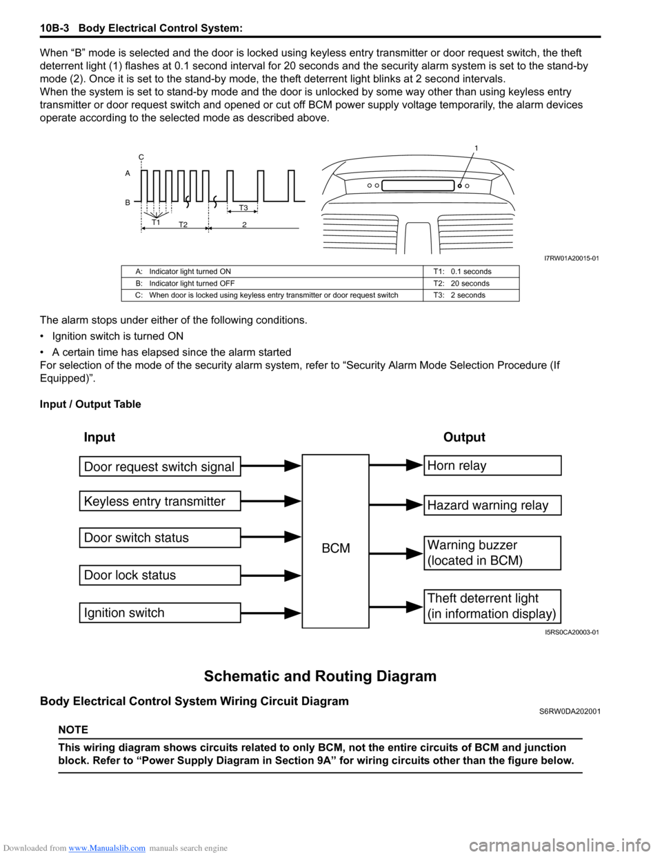
When “B” mode is selected and the door is locked using keyless entry transmitter or door request switch, the theft
deterrent light (1) flashes at 0.1 second interval for 20 seconds and the security alarm system is set to the stand-by
mode (2). Once it is set to the stand-by mode, the theft deterrent light blinks at 2 second intervals.
When the system is set to stand-by mode and the door is unlocked by some way other than using keyless entry
transmitter or door request switch and opened or cut off BCM power supply voltage temporarily, the alarm devices
operate according to the selected mode as described above.
The alarm stops under either of the following conditions.
• Ignition switch is turned ON
• A certain time has elapsed since the alarm started
For selection of the mode of the security alarm system, refer to “Security Alarm Mode Selection Procedure (If
Equipped)”.
Input / Output Table
Schematic and Routing Diagram
Body Electrical Control System Wiring Circuit DiagramS6RW0DA202001
NOTE
This wiring diagram shows circuits related to only BCM, not the entire circuits of BCM and junction
block. Refer to “Power Supply Diagram in Section 9A” for wiring circuits other than the figure below.
B AT3
T1
T2 2 C
1
I7RW01A20015-01
A: Indicator light turned ON T1: 0.1 seconds
B: Indicator light turned OFF T2: 20 seconds
C: When door is locked using keyless entry transmitter or door request switch T3: 2 seconds
Input Output
Keyless entry transmitter
Door switch status
Door lock statusBCMHorn relay
Theft deterrent light
(in information display)
Warning buzzer
(located in BCM)
Hazard warning relay
Door request switch signal
Ignition switch
I5RS0CA20003-01