2006 SUZUKI SX4 warning
[x] Cancel search: warningPage 1042 of 1556
Downloaded from www.Manualslib.com manuals search engine 8B-3 Air Bag System:
WARNING!
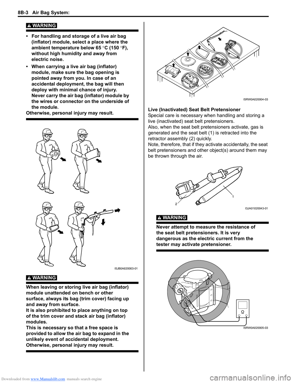
• For handling and storage of a live air bag
(inflator) module, select a place where the
ambient temperature below 65 °C (150 °F),
without high humidity and away from
electric noise.
• When carrying a live air bag (inflator)
module, make sure the bag opening is
pointed away from you. In case of an
accidental deployment, the bag will then
deploy with minimal chance of injury.
Never carry the air bag (inflator) module by
the wires or connector on the underside of
the module.
Otherwise, personal injury may result.
WARNING!
When leaving or storing live air bag (inflator)
module unattended on bench or other
surface, always its bag (trim cover) facing up
and away from surface.
It is also prohibited to place anything on top
of the trim cover and stack air bag (inflator)
modules.
This is necessary so that a free space is
provided to allow the air bag to expand in the
unlikely event of accidental deployment.
Otherwise, personal injury may result.
Live (Inactivated) Seat Belt Pretensioner
Special care is necessary when handling and storing a
live (inactivated) seat belt pretensioners.
Also, when the seat belt pretensioners activate, gas is
generated and the seat belt (1) is retracted into the
retractor assembly (2) quickly.
Note, therefore, that if they activate accidentally, the seat
belt pretensioners and other object(s) around them may
be thrown through the air.
WARNING!
Never attempt to measure the resistance of
the seat belt pretensioners. It is very
dangerous as the electric current from the
tester may activate pretensioner.
I5JB0A820003-01
I5RW0A820004-03
I3JA01820043-01
I5RW0A820005-03
Page 1043 of 1556
Downloaded from www.Manualslib.com manuals search engine Air Bag System: 8B-4
• Never attempt to disassemble the seat belt
pretensioners (retractor assembly).
• If any abnormality is found, be sure to replace it with
new one as an assembly.
• When an abnormality is noted as existing in the live
(inactivated) seat belt pretensioner, be sure to activate
it before discarding it.
• When grease, cleaning agent oil, water, etc., got on
the seat belt pretensioners (retractor assembly), wipe
it off immediately with a dry cloth.
• If seat belt pretensioner was dropped from a height of
30 cm (1 ft) or more, it should be replaced with a new
one as an assembly.
WARNING!
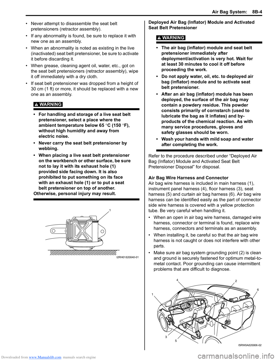
• For handling and storage of a live seat belt
pretensioner, select a place where the
ambient temperature below 65 °C (150 °F),
without high humidity and away from
electric noise.
• Never carry the seat belt pretensioner by
webbing.
• When placing a live seat belt pretensioner
on the workbench or other surface, be sure
not to lay it with its exhaust hole (1)
provided side facing down. It is also
prohibited to put something on its face
with an exhaust hole (1) or to put a seat
belt pretensioner on top of another.
Otherwise, personal injury may result.
Deployed Air Bag (Inflator) Module and Activated
Seat Belt Pretensioner
WARNING!
• The air bag (inflator) module and seat belt
pretensioner immediately after
deployment/activation is very hot. Wait for
at least 30 minutes to cool it off before
proceeding the work.
• Do not apply water, oil, etc. to deployed air
bag (inflator) module and to activate seat
belt pretensioner.
• After an air bag (inflator) module has been
deployed, the surface of the air bag may
contain a powdery residue. This powder
consists primarily of cornstarch (used to
lubricate the bag as it inflates) and by-
products of the chemical reaction. As with
many service procedures, gloves and
safety glasses should be worn.
• Wash your hands with mild soap and water
after completing the work.
Refer to the procedure described under “Deployed Air
Bag (Inflator) Module and Activated Seat Belt
Pretensioner Disposal” for disposal.
Air Bag Wire Harness and Connector
Air bag wire harness is included in main harness (1),
instrument panel harness (4), floor harness (3), seat
harness (5) and curtain air bag harness (6). Air bag wire
harness can be identified easily as the part of connector
side wire harness is covered with a yellow protection
tube. Be very careful when handling it.
• When an open in air bag wire harness, damaged wire
harness, connector or terminal is found, replace wire
harness, connectors and terminals as an assembly.
• When installing it, be careful so that the air bag wire
harness is not caught or does not interfere with other
parts.
• Make sure air bag system grounding point (2) is clean
and ground is securely fastened for optimum metal-to-
metal contact. Poor grounding can cause intermittent
problems that are difficult to diagnose.
1
I2RH01820048-01
4
12
6
3
5
I5RW0A820006-02
Page 1044 of 1556
Downloaded from www.Manualslib.com manuals search engine 8B-5 Air Bag System:
Precautions on Disposal of Air Bag and Seat
Belt Pretensioner
S6RW0D8200003
Do not dispose of the live (undeployed) air bag (inflator)
modules and the live (inactivated) seat belt
pretensioners.
When disposal is necessary, be sure to deploy / activate
the air bag and seat belt pretensioner according to
deployment / activation procedure described in “Air Bag
(Inflator) Module and Seat Belt Pretensioner Disposal”.
WARNING!
Failure to follow proper air bag (inflator)
module and seat belt pretensioner disposal
procedures can result in air bag deployment
and pretensioner activation which could
cause personal injury. Undeployed air bag
(inflator) module and inactivated seat belt
pretensioner must not be disposed of
through normal refuse channels.
The undeployed air bag (inflator) module and
inactivated seat belt pretensioner contain
substances that can cause severe illness or
personal injury if the sealed container is
damaged during disposal.
General Description
Air Bag System ConstructionS6RW0D8201001
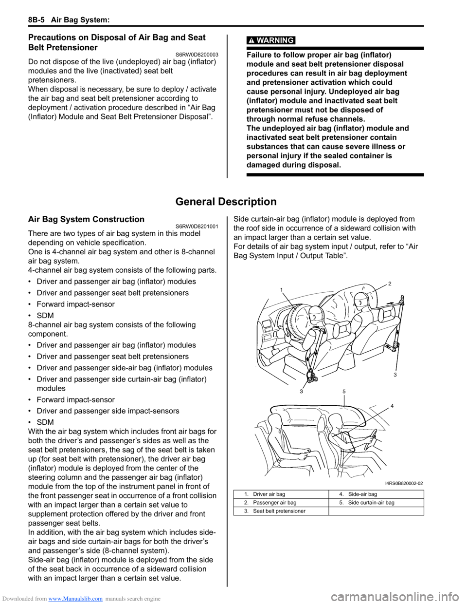
There are two types of air bag system in this model
depending on vehicle specification.
One is 4-channel air bag system and other is 8-channel
air bag system.
4-channel air bag system consists of the following parts.
• Driver and passenger air bag (inflator) modules
• Driver and passenger seat belt pretensioners
• Forward impact-sensor
•SDM
8-channel air bag system consists of the following
component.
• Driver and passenger air bag (inflator) modules
• Driver and passenger seat belt pretensioners
• Driver and passenger side-air bag (inflator) modules
• Driver and passenger side curtain-air bag (inflator)
modules
• Forward impact-sensor
• Driver and passenger side impact-sensors
•SDM
With the air bag system which includes front air bags for
both the driver’s and passenger’s sides as well as the
seat belt pretensioners, the sag of the seat belt is taken
up (for seat belt with pretensioner), the driver air bag
(inflator) module is deployed from the center of the
steering column and the passenger air bag (inflator)
module from the top of the instrument panel in front of
the front passenger seat in occurrence of a front collision
with an impact larger than a certain set value to
supplement protection offered by the driver and front
passenger seat belts.
In addition, with the air bag system which includes side-
air bags and side curtain-air bags for both the driver’s
and passenger’s side (8-channel system).
Side-air bag (inflator) module is deployed from the side
of the seat back in occurrence of a sideward collision
with an impact larger than a certain set value.Side curtain-air bag (inflator) module is deployed from
the roof side in occurrence of a sideward collision with
an impact larger than a certain set value.
For details of air bag system input / output, refer to “Air
Bag System Input / Output Table”.
1. Driver air bag 4. Side-air bag
2. Passenger air bag 5. Side curtain-air bag
3. Seat belt pretensioner
I4RS0B820002-02
Page 1048 of 1556
![SUZUKI SX4 2006 1.G Service Workshop Manual Downloaded from www.Manualslib.com manuals search engine 8B-9 Air Bag System:
Terminal arrangement of SDM (viewed from harness side)
[A]: Shorting bar 11. BCM 25. Driver seat belt pretensioner
[B]: C SUZUKI SX4 2006 1.G Service Workshop Manual Downloaded from www.Manualslib.com manuals search engine 8B-9 Air Bag System:
Terminal arrangement of SDM (viewed from harness side)
[A]: Shorting bar 11. BCM 25. Driver seat belt pretensioner
[B]: C](/manual-img/20/7612/w960_7612-1047.png)
Downloaded from www.Manualslib.com manuals search engine 8B-9 Air Bag System:
Terminal arrangement of SDM (viewed from harness side)
[A]: Shorting bar 11. BCM 25. Driver seat belt pretensioner
[B]: Connector 12. Combination meter 26. Passenger seat belt pretensioner
[C]: Junction block with BCM model 13. “AIR BAG” warning light27. Driver side-air bag (inflator) module (8-channel system)
[D]: Junction block without BCM model 14. Light driver 28. Passenger side-air bag (inflator) module (8-channel system)
1. Battery 15. SDM 29. Driver side curtain-air bag (inflator) module (8-channel
system)
2. Main fuse 16. To HVAC control module (auto A/C model) 30. Passenger side curtain-air bag (inflator) module (8-channel
system)
3. Fuse 17. Data link connector (DLC) 31. Safing power driver
4. Individual circuit fuse box No.1 18. Forward impact-sensor 32. X-Y-G (longitudinal / lateral acceleration)
5. “IGN” fuse 19. Driver side impact-sensor (8-channel
system)33. DC / DC converter
6. Ignition switch 20. Passenger side impact-sensor (8-channel
system)34. Mechanical longitudinal G sensor (switch)
7. Junction block assembly 21. Ground for air bag system 35. Back up capacitor
8. “DOME” fuse 22. Contact coil assembly
9. “METER” fuse 23. Driver air bag (inflator) module
10. “A/B” fuse 24. Passenger air bag (inflator) module
1
2 3 4 5 6 7 8 9 10 11 12 13 14 15 16 17 18 19 20 21 22 23 24 25 26
27 28 29 30 31 32 33 34 35 36 37 38 39 40 41 42 43 44 45 46 47 48 49 50 51
1
I7RW01822003-02
1. SDM Connector “L04”
Page 1049 of 1556
Downloaded from www.Manualslib.com manuals search engine Air Bag System: 8B-10
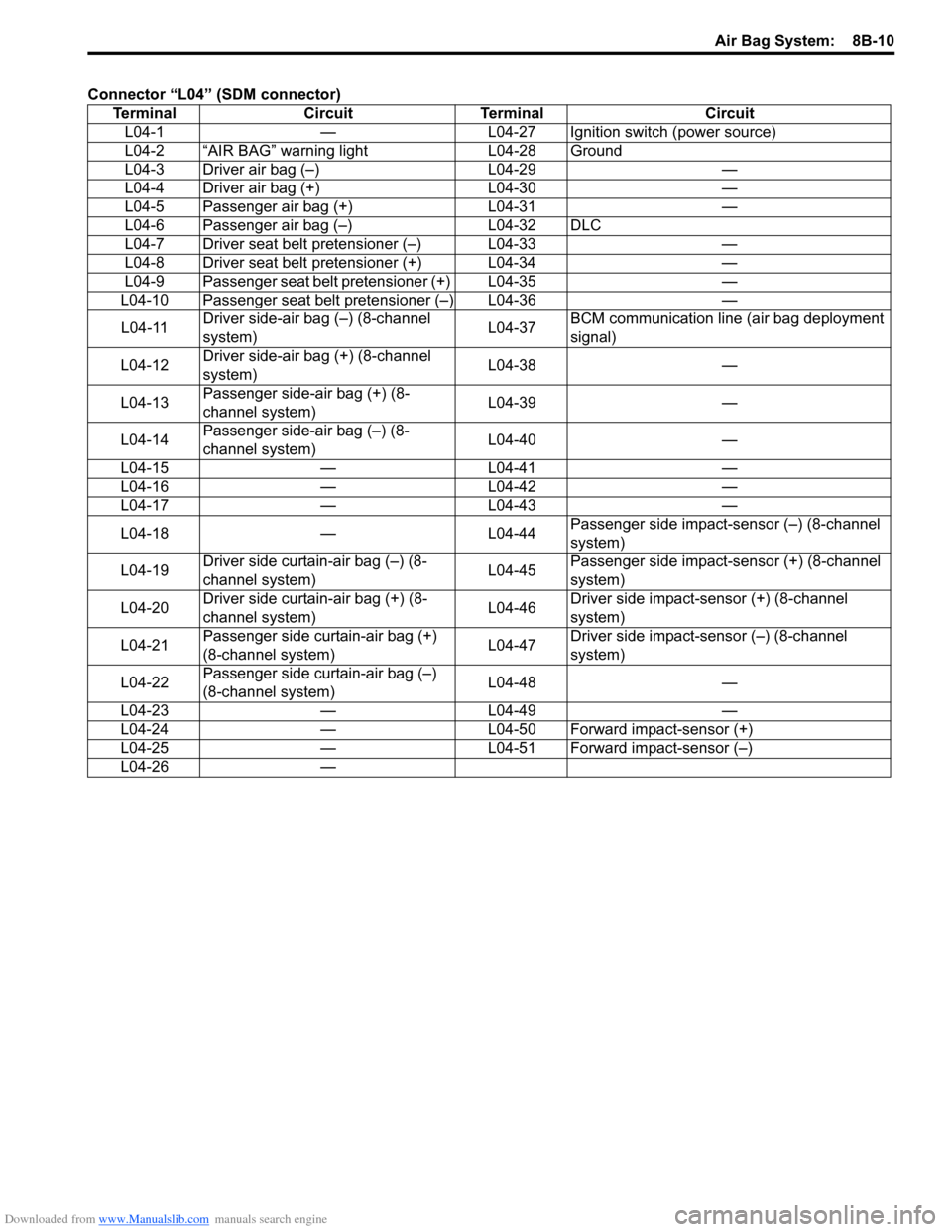
Connector “L04” (SDM connector)
Terminal Circuit Terminal Circuit
L04-1 — L04-27 Ignition switch (power source)
L04-2 “AIR BAG” warning light L04-28 Ground
L04-3 Driver air bag (–) L04-29 —
L04-4 Driver air bag (+) L04-30 —
L04-5 Passenger air bag (+) L04-31 —
L04-6 Passenger air bag (–) L04-32 DLC
L04-7 Driver seat belt pretensioner (–) L04-33 —
L04-8 Driver seat belt pretensioner (+) L04-34 —
L04-9 Passenger seat belt pretensioner (+) L04-35 —
L04-10 Passenger seat belt pretensioner (–) L04-36 —
L04-11 Driver side-air bag (–) (8-channel
system)L04-37 BCM communication line (air bag deployment
signal)
L04-12 Driver side-air bag (+) (8-channel
system)L04-38 —
L04-13 Passenger side-air bag (+) (8-
channel system)L04-39 —
L04-14 Passenger side-air bag (–) (8-
channel system)L04-40 —
L04-15 — L04-41 —
L04-16 — L04-42 —
L04-17 — L04-43 —
L04-18 — L04-44 Passenger side impact-sensor (–) (8-channel
system)
L04-19 Driver side curtain-air bag (–) (8-
channel system)L04-45 Passenger side impact-sensor (+) (8-channel
system)
L04-20 Driver side curtain-air bag (+) (8-
channel system)L04-46 Driver side impact-sensor (+) (8-channel
system)
L04-21 Passenger side curtain-air bag (+)
(8-channel system)L04-47 Driver side impact-sensor (–) (8-channel
system)
L04-22 Passenger side curtain-air bag (–)
(8-channel system)L04-48 —
L04-23 — L04-49 —
L04-24 — L04-50 Forward impact-sensor (+)
L04-25 — L04-51 Forward impact-sensor (–)
L04-26 —
Page 1051 of 1556
Downloaded from www.Manualslib.com manuals search engine Air Bag System: 8B-12
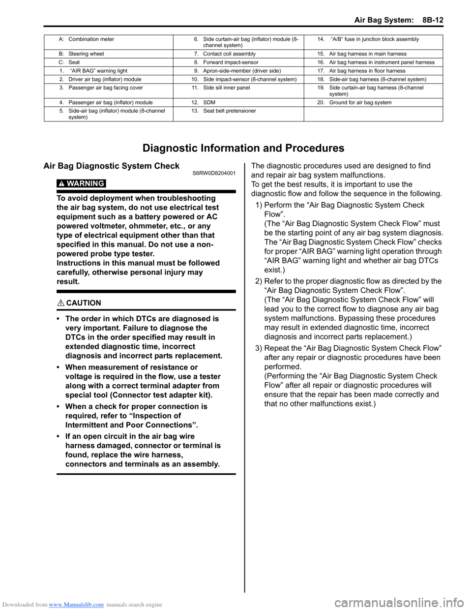
Diagnostic Information and Procedures
Air Bag Diagnostic System CheckS6RW0D8204001
WARNING!
To avoid deployment when troubleshooting
the air bag system, do not use electrical test
equipment such as a battery powered or AC
powered voltmeter, ohmmeter, etc., or any
type of electrical equipment other than that
specified in this manual. Do not use a non-
powered probe type tester.
Instructions in this manual must be followed
carefully, otherwise personal injury may
result.
CAUTION!
• The order in which DTCs are diagnosed is
very important. Failure to diagnose the
DTCs in the order specified may result in
extended diagnostic time, incorrect
diagnosis and incorrect parts replacement.
• When measurement of resistance or
voltage is required in the flow, use a tester
along with a correct terminal adapter from
special tool (Connector test adapter kit).
• When a check for proper connection is
required, refer to “Inspection of
Intermittent and Poor Connections”.
• If an open circuit in the air bag wire
harness damaged, connector or terminal is
found, replace the wire harness,
connectors and terminals as an assembly.
The diagnostic procedures used are designed to find
and repair air bag system malfunctions.
To get the best results, it is important to use the
diagnostic flow and follow the sequence in the following.
1) Perform the “Air Bag Diagnostic System Check
Flow”.
(The “Air Bag Diagnostic System Check Flow” must
be the starting point of any air bag system diagnosis.
The “Air Bag Diagnostic System Check Flow” checks
for proper “AIR BAG” warning light operation through
“AIR BAG” warning light and whether air bag DTCs
exist.)
2) Refer to the proper diagnostic flow as directed by the
“Air Bag Diagnostic System Check Flow”.
(The “Air Bag Diagnostic System Check Flow” will
lead you to the correct flow to diagnose any air bag
system malfunctions. Bypassing these procedures
may result in extended diagnostic time, incorrect
diagnosis and incorrect parts replacement.)
3) Repeat the “Air Bag Diagnostic System Check Flow”
after any repair or diagnostic procedures have been
performed.
(Performing the “Air Bag Diagnostic System Check
Flow” after all repair or diagnostic procedures will
ensure that the repair has been made correctly and
that no other malfunctions exist.)
A: Combination meter 6. Side curtain-air bag (inflator) module (8-
channel system)14. “A/B” fuse in junction block assembly
B: Steering wheel 7. Contact coil assembly 15. Air bag harness in main harness
C: Seat 8. Forward impact-sensor 16. Air bag harness in instrument panel harness
1. “AIR BAG” warning light 9. Apron-side-member (driver side) 17. Air bag harness in floor harness
2. Driver air bag (inflator) module 10. Side impact-sensor (8-channel system) 18. Side-air bag harness (8-channel system)
3. Passenger air bag facing cover 11. Side sill inner panel 19. Side curtain-air bag harness (8-channel
system)
4. Passenger air bag (inflator) module 12. SDM 20. Ground for air bag system
5. Side-air bag (inflator) module (8-channel
system)13. Seat belt pretensioner
Page 1052 of 1556
Downloaded from www.Manualslib.com manuals search engine 8B-13 Air Bag System:
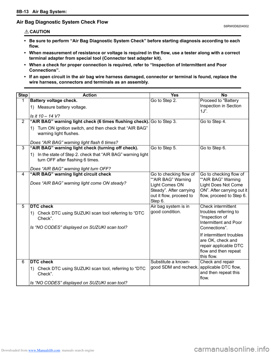
Air Bag Diagnostic System Check FlowS6RW0D8204002
CAUTION!
• Be sure to perform “Air Bag Diagnostic System Check” before starting diagnosis according to each
flow.
• When measurement of resistance or voltage is required in the flow, use a tester along with a correct
terminal adapter from special tool (Connector test adapter kit).
• When a check for proper connection is required, refer to “Inspection of Intermittent and Poor
Connections”.
• If an open circuit in the air bag wire harness damaged, connector or terminal is found, replace the
wire harness, connectors and terminals as an assembly.
Step Action Yes No
1Battery voltage check.
1) Measure battery voltage.
Is it 10 – 14 V?Go to Step 2. Proceed to “Battery
Inspection in Section
1J”.
2“AIR BAG” warning light check (6 times flushing check).
1) Turn ON ignition switch, and then check that “AIR BAG”
warning light flushes.
Does “AIR BAG” warning light flash 6 times?Go to Step 3. Go to Step 4.
3“AIR BAG” warning light check (turning off check).
1) In the state of Step 2. check that “AIR BAG” warning light
turn OFF after flashing 6 times.
Does “AIR BAG” warning light turn OFF?Go to Step 5. Go to Step 6.
4“AIR BAG” warning light circuit check
Does “AIR BAG” warning light come ON steady?Go to checking flow of
““AIR BAG” Warning
Light Comes ON
Steady”. After carrying
out it flow, proceed to
St ep 6 .Go to checking flow of
““AIR BAG” Warning
Light Does Not Come
ON”. After carrying out it
flow, proceed to Step 6.
5DTC check
1) Check DTC using SUZUKI scan tool referring to “DTC
Check”.
Is “NO CODES” displayed on SUZUKI scan tool?Air bag system is in
good condition.Check intermittent
troubles referring to
“Inspection of
Intermittent and Poor
Connections”.
If intermittent troubles
are OK, check and
repair applicable DTC
flow and then repeat
this flow.
6DTC check
1) Check DTC using SUZUKI scan tool, referring to “DTC
Check”.
Is “NO CODES” displayed on SUZUKI scan tool?Substitute a known-
good SDM and recheck.Check and repair
applicable DTC flow,
and then repeat this
flow.
Page 1053 of 1556
Downloaded from www.Manualslib.com manuals search engine Air Bag System: 8B-14
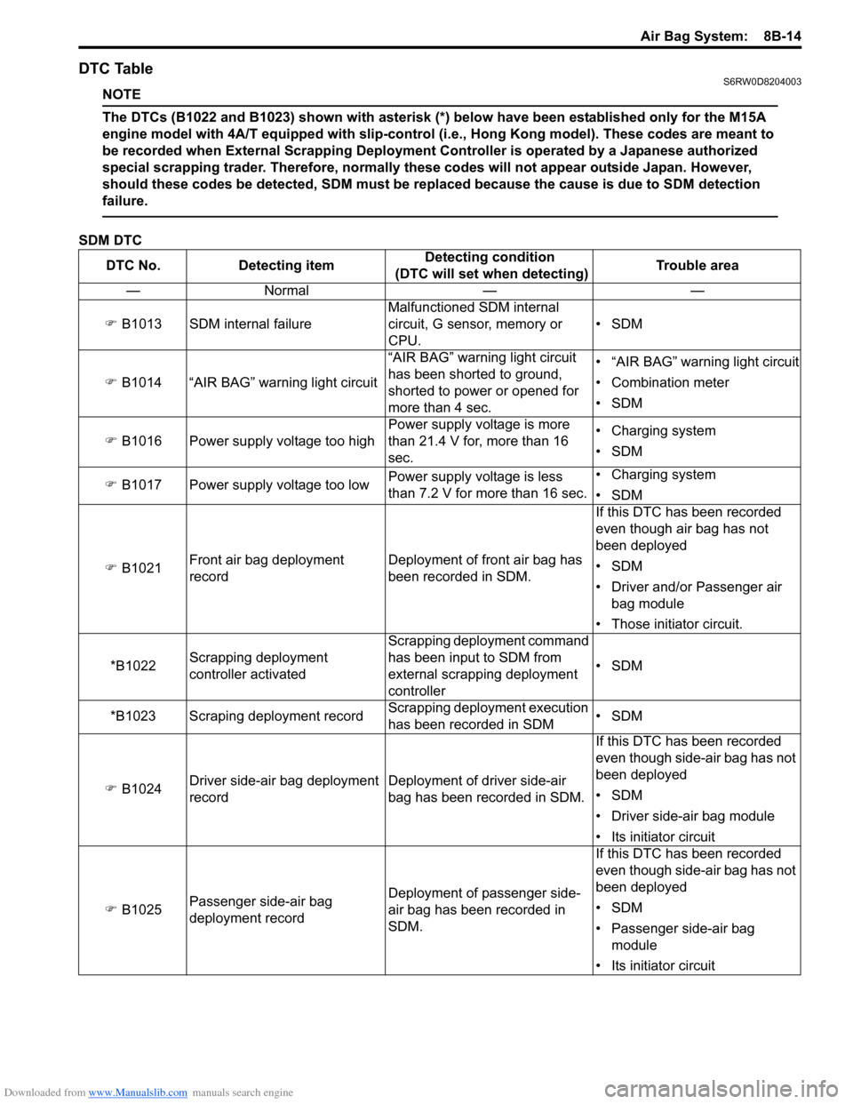
DTC TableS6RW0D8204003
NOTE
The DTCs (B1022 and B1023) shown with asterisk (*) below have been established only for the M15A
engine model with 4A/T equipped with slip-control (i.e., Hong Kong model). These codes are meant to
be recorded when External Scrapping Deployment Controller is operated by a Japanese authorized
special scrapping trader. Therefore, normally these codes will not appear outside Japan. However,
should these codes be detected, SDM must be replaced because the cause is due to SDM detection
failure.
SDM DTC
DTC No. Detecting itemDetecting condition
(DTC will set when detecting)Trouble area
—Normal — —
�) B1013 SDM internal failureMalfunctioned SDM internal
circuit, G sensor, memory or
CPU.•SDM
�) B1014 “AIR BAG” warning light circuit“AIR BAG” warning light circuit
has been shorted to ground,
shorted to power or opened for
more than 4 sec.• “AIR BAG” warning light circuit
• Combination meter
•SDM
�) B1016 Power supply voltage too highPower supply voltage is more
than 21.4 V for, more than 16
sec.• Charging system
•SDM
�) B1017 Power supply voltage too lowPower supply voltage is less
than 7.2 V for more than 16 sec.• Charging system
•SDM
�) B1021Front air bag deployment
recordDeployment of front air bag has
been recorded in SDM.If this DTC has been recorded
even though air bag has not
been deployed
•SDM
• Driver and/or Passenger air
bag module
• Those initiator circuit.
*B1022Scrapping deployment
controller activatedScrapping deployment command
has been input to SDM from
external scrapping deployment
controller•SDM
*B1023 Scraping deployment recordScrapping deployment execution
has been recorded in SDM•SDM
�) B1024Driver side-air bag deployment
recordDeployment of driver side-air
bag has been recorded in SDM.If this DTC has been recorded
even though side-air bag has not
been deployed
•SDM
• Driver side-air bag module
• Its initiator circuit
�) B1025Passenger side-air bag
deployment recordDeployment of passenger side-
air bag has been recorded in
SDM.If this DTC has been recorded
even though side-air bag has not
been deployed
•SDM
• Passenger side-air bag
module
• Its initiator circuit