2006 SUZUKI SX4 warning
[x] Cancel search: warningPage 957 of 1556

Downloaded from www.Manualslib.com manuals search engine Air Conditioning System: Manual Type 7B-17
Repair Instructions
Operation Procedure for Refrigerant ChargeS6RW0D7216001
WARNING!
• Your eyes should not be exposed to refrigerant (liquid).
Any liquid HFC-134a (R-134a) escaping by accident shows a temperature as low as approximately –
6 °C (21.2 °F) below freezing point. Should liquid HFC-134a (R-134a) is exposed to your eyes, it may
cause a serious injury. To protect your eyes from such accident, it is necessary to always wear
goggles. Should it occur that HFC-134a (R-134a) is exposed to your eyes, consult a doctor
immediately.
– Do not use your hand to rub the affected eye(s). Instead, use fresh cold water to splash it over the
affected area to gradually raise temperature of such area above freezing point.
– Obtain proper treatment as soon as possible from a doctor or eye specialist.
• Should the liquid refrigerant HFC-134a (R-134a) is exposed to your skin, the affected area should be
treated in the same manner as when skin is frostbitten or frozen.
• Do not handle refrigerant near any place where welding or steam cleaning is performed.
• Refrigerant should be kept in a cold and dark place. It should never be stored in any place where
temperature is high, e.g. where exposed to direct sun light, close to fire or inside vehicle (including
trunk room).
• Avoid breathing fume produced when HFC-134a (R-134a) is burned. Such fume may be hazardous to
your health.
Start evacuation.Start evacuation.
Stop evacuation.Stop evacuation.
15 minutes (above -100 kPa)15 minutes (above -100 kPa)
Wait 10 minutesWait 10 minutes
Check A/C system forCheck A/C system for
pressure tighteness.pressure tighteness.
Recharge A/C system withRecharge A/C system withrefrigerant.refrigerant.
Check A/C system for refrigerantCheck A/C system for refrigerantleaks and amount of refrigerantleaks and amount of refrigerantcharged.charged.
Performance testPerformance test
Inspect and repair connections.Inspect and repair connections.
If gauge showsIf gauge showsabnormal conditionsabnormal conditions
Recharge 430 20 g ofRecharge 430 20 g ofrefrigerant.refrigerant.
I5RW0A721011-01
Page 960 of 1556

Downloaded from www.Manualslib.com manuals search engine 7B-20 Air Conditioning System: Manual Type
Charge
CAUTION!
• Because the sight glass is not used for this
A/C system, do not perform an additional
charge to the A/C system. To charge the
proper amount of refrigerant, recover and
evacuate the A/C system first. And then,
charge the proper amount of refrigerant
into the A/C system.
• Always charge refrigerant through low
pressure side of A/C system after the initial
charge is performed from the high
pressure side with the engine stopped.
• Never charge refrigerant through high
pressure side of A/C system with engine
running.
• Do not charge refrigerant while
compressor is hot.
• When installing tap valve to refrigerant
container to make a hole there through,
carefully follow directions given by
manufacturer.
• A pressure gauge should always be used
before and during refrigerant charge.
• The refrigerant container should be
emptied of refrigerant when discarding it.
• The refrigerant container should not be
heated up to 40 °C (104 °F) or over.
• Refrigerant container should not be
reversed in direction during refrigerant
charge. Reversing in direction causes
liquid refrigerant to enter compressor,
causing troubles, such as compression of
liquid refrigerant and the like.
NOTE
The air conditioning system contains HFC-
134a (R-134a).
Described here is a method to charge the air
conditioning system with refrigerant from the
refrigerant service container.
When charging refrigerant recovered by
using the refrigerant and recycling
equipment (when recycling refrigerant),
follow the procedure described in the
equipment manufacturer’s instruction
manual.
The initial charge of the A/C system is performed
through the high pressure side with the engine stopped.
And next, this method must be followed by charging from
the low pressure side with the engine running.
1) Check if hoses are routed properly after evacuating
the system.
2) Connect low charging hose (1) and high charging
hose (2) of the manifold gauge set (3) in position.
Then, open refrigerant container valve (4) to purge
the charging line.
3) Open the high pressure side valve (5) and charge
refrigerant to system.
4) After a while, open the low pressure side valve (6)
and close the high pressure side valve.
WARNING!
Make sure that high pressure side valve is
closed securely.
5) Start engine and keep engine speed at 1500 r/min,
and then operate A/C system.
6) Charge A/C system with refrigerant in vapor state. At
this time, refrigerant container should be held
upright.
4
3
6
2
1 5
I7RW01721012-01
Page 961 of 1556

Downloaded from www.Manualslib.com manuals search engine Air Conditioning System: Manual Type 7B-21
7) When refrigerant container (1) is emptied, use the
following procedure to replace it with a new
refrigerant container.
a) Close low pressure valve.
b) Replace empty container with a refrigerant
container which has been charged with
refrigerant. When using refrigerant container tap
valve (2), use the following procedure for
replacement.
i) Retract needle (3) and remove refrigerant
container tap valve by loosening its plate nut
(4).
ii) Install the refrigerant container tap valve to a
new refrigerant container.
c) Purge any air existing in center charging hose.
When using refrigerant container tap valve, use
the following procedure to purge air.
i) Once fully tighten refrigerant container tap
valve (1), and then loosen (open) plate nut
(2) slightly.
ii) Open low pressure side valve (3) of manifold
gauge set (4) a little.
iii) As soon as refrigerant comes out with a
“hiss” through a clearance between
refrigerant container and tap valve, tighten
plate nut as well as low pressure side valve.
iv) Turn handle of tap valve clockwise so that its
needle is screwed into the new container to
make a hole for refrigerant flow.8) After the system has been charged with specified
amount of refrigerant or when low pressure gauge
(1) and high pressure gauge (2) have indicated the
following specified value, close low pressure side
valve (3) on manifold gauge set (4).
Specified amount of refrigerant
430 ± 20 g (15.2 ± 0.7 oz))
Low side and high side pressure example
Removal of Manifold Gauge Set
WARNING!
High pressure side is under high pressure.
Therefore, be careful not to get injured
especially on your eyes and skin.
For the A/C system charged with the specified amount of
refrigerant, remove manifold gauge set as follows:
1) Close low pressure side valve of manifold gauge set.
(The high pressure side valve is closed continuously
during the process of charging.)
2) Close refrigerant container valve.
3) Stop engine.
4) Using shop rag, remove charging hoses from service
valves. This operation must be performed quickly.
5) Put caps on service valves.
I2RH01720018-01
I2RH01720019-01
Gauges should read as follows when ambient
temperature is 30 °C (86 °F).
Pressure
on high pressure gauge1130 – 1560 kPa
(11.4 – 15.6 kgf/cm
2)
(162.3 – 221.8 psi)
Pressure
on low pressure gauge270 – 390 kPa
(2.7 – 3.9 kgf/cm
2)
(38.8 – 56.0 psi)
4
2
1
3
I7RW01721013-02
Page 962 of 1556

Downloaded from www.Manualslib.com manuals search engine 7B-22 Air Conditioning System: Manual Type
Check A/C System for Refrigerant Leaks
Whenever a refrigerant leak is suspected in the system
or any service operation has been performed which may
result in malfunction of lines and connections, it is
advisable to check for leaks.
Common sense should be used during refrigerant leak
test, since the need and extent of any such test will, in
general, depend upon the nature of a complaint and the
type of a service performed on the system.
Liquid leak detector
WARNING!
• To prevent explosions and fires, make sure
that there are no flammables in the vicinity.
• When the refrigerant exposed to fire, it
turns into a poisonous gas (phosgene). Do
not inhale this gas.
There is a number of fittings and places throughout the
A/C system where a liquid leak detector solution may be
used to pinpoint refrigerant leaks.
By merely applying the solution to the area in question
with a swab, such as attached to the cap of a vial,
bubbles will form within seconds if there is a leak.
For confined areas, such as sections of the evaporator
and condenser, an electronic (refrigerant) leak detector
is more practical for determining leaks.
Special tool
(A): 09990–86012
Condenser Cooling Fan Removal and
Installation
S6RW0D7216002
CAUTION!
Be careful not to damage fins of radiator. If
radiator fin is bent, straighten it by using flat
head screwdriver or pair of pliers.
Removal
1) Disconnect negative (–) cable at battery.
2) Disconnect condenser cooling fan motor coupler.
3) Remove reservoir (1) from radiator.
4) Remove condenser cooling fan (2) from radiator (3).
Installation
Reverse removal procedure to install condenser cooling
fan.
(A)
I5RW0A721054-01
13
2
I5RW0A721017-01
Page 978 of 1556

Downloaded from www.Manualslib.com manuals search engine 7B-38 Air Conditioning System: Automatic Type
Automatic Type
Precautions
A/C System CautionS6RW0D7220001
Refer to “A/C System Caution”.
Precautions in Diagnosing TroubleS6RW0D7220002
• Do not disconnect couplers from HVAC control module, battery cable from battery, HVAC control module ground
wire harness from body or main fuse before confirming diagnostic information (diagnostic trouble code) stored in
HVAC control module memory.
• Diagnostic information (diagnostic trouble code) stored in HVAC control module can be checked by display of HVAC
control module. Also, it can be checked by using SUZUKI scan tool. Before checking diagnostic information
(diagnostic trouble code), read this manual and operator's manual for SUZUKI scan tool to know how to read
diagnostic information (diagnostic trouble code).
• When trouble is diagnosed using diagnostic information (diagnostic trouble code) on display of HVAC control
module, keep in your mind that each diagnostic information (diagnostic trouble code) has priority, and only
diagnostic information (diagnostic trouble code) which has the highest priority is indicated. Therefore, after
troubleshooting the malfunction, make sure if there exists any other diagnostic information (diagnostic trouble
code).
• Be sure to read “Air Bag Warning in Section 00” before inspection.
Precautions on Servicing A/C SystemS6RW0D7220003
Refer to “Precautions on Servicing A/C System”.
Page 1029 of 1556

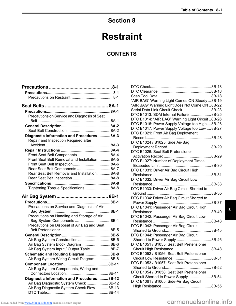
Downloaded from www.Manualslib.com manuals search engine Table of Contents 8- i
8
Section 8
CONTENTS
Restraint
Precautions ................................................. 8-1
Precautions............................................................. 8-1
Precautions on Restraint ....................................... 8-1
Seat Belts ................................................. 8A-1
Precautions........................................................... 8A-1
Precautions on Service and Diagnosis of Seat
Belt .................................................................... 8A-1
General Description ............................................. 8A-2
Seat Belt Construction ........................................ 8A-2
Diagnostic Information and Procedures ............ 8A-3
Repair and Inspection Required after
Accident ............................................................ 8A-3
Repair Instructions .............................................. 8A-4
Front Seat Belt Components ............................... 8A-4
Front Seat Belt Removal and Installation ............ 8A-5
Front Seat Belt Inspection................................... 8A-6
Rear Seat Belt Components ............................... 8A-7
Rear Seat Belt Removal and Installation ............ 8A-8
Rear Seat Belt Inspection ................................... 8A-8
Specifications....................................................... 8A-8
Tightening Torque Specifications ........................ 8A-8
Air Bag System ........................................ 8B-1
Precautions........................................................... 8B-1
Precautions on Service and Diagnosis of Air
Bag System....................................................... 8B-1
Precautions on Handling and Storage of Air
Bag System Components ................................. 8B-1
Precautions on Disposal of Air Bag and Seat
Belt Pretensioner .............................................. 8B-5
General Description ............................................. 8B-5
Air Bag System Construction .............................. 8B-5
Air Bag System Block Diagram ........................... 8B-6
Air Bag System Input / Output Table .................. 8B-7
Schematic and Routing Diagram ........................ 8B-8
Air Bag System Wiring Circuit Diagram .............. 8B-8
Component Location ......................................... 8B-11
Air Bag System Components, Wiring and
Connectors Location ....................................... 8B-11
Diagnostic Information and Procedures .......... 8B-12
Air Bag Diagnostic System Check .................... 8B-12
Air Bag Diagnostic System Check Flow ............ 8B-13
DTC Table ......................................................... 8B-14DTC Check........................................................ 8B-18
DTC Clearance ................................................. 8B-18
Scan Tool Data ................................................. 8B-18
“AIR BAG” Warning Light Comes ON Steady ... 8B-19
“AIR BAG” Warning Light Does Not Come ON .. 8B-22
Serial Data Link Circuit Check .......................... 8B-23
DTC B1013: SDM Internal Failure .................... 8B-25
DTC B1014: “AIR BAG” Warning Light Circuit .. 8B-26
DTC B1016: Power Supply Voltage too High.... 8B-26
DTC B1017: Power Supply Voltage too Low .... 8B-27
DTC B1021: Front Air Bag Deployment
Record............................................................. 8B-28
DTC B1024 / B1025: Side Air-Bag
Deployment Record ........................................ 8B-29
DTC B1026: Seat Belt Pretensioner
Activation Record ............................................ 8B-29
DTC B1027: Number of Deployment Times
Exceeded Limit................................................ 8B-30
DTC B1031: Driver Air Bag Circuit High
Resistance ...................................................... 8B-31
DTC B1032: Driver Air Bag Circuit Low
Resistance ...................................................... 8B-33
DTC B1033: Driver Air Bag Circuit Shorted to
Ground ............................................................ 8B-35
DTC B1034: Driver Air Bag Circuit Shorted to
Power Supply .................................................. 8B-37
DTC B1041: Passenger Air Bag Circuit High
Resistance ...................................................... 8B-40
DTC B1042: Passenger Air Bag Circuit Low
Resistance ...................................................... 8B-43
DTC B1043: Passenger Air Bag Circuit
Shorted to Ground........................................... 8B-45
DTC B1044: Passenger Air Bag Circuit
Shorted to Power Supply ................................ 8B-46
DTC B1051 / B1055: Seat Belt Pretensioner
Circuit High Resistance ................................... 8B-48
DTC B1052 / B1056: Seat Belt Pretensioner
Circuit Low Resistance.................................... 8B-51
DTC B1053 / B1057: Seat Belt Pretensioner
Shorted to Ground........................................... 8B-52
DTC B1054 / B1058: Seat Belt Pretensioner
Circuit Shorted to Power Supply ..................... 8B-54
DTC B1061 / B1065: Side-Air Bag Circuit
High Resistance .............................................. 8B-55
Page 1031 of 1556

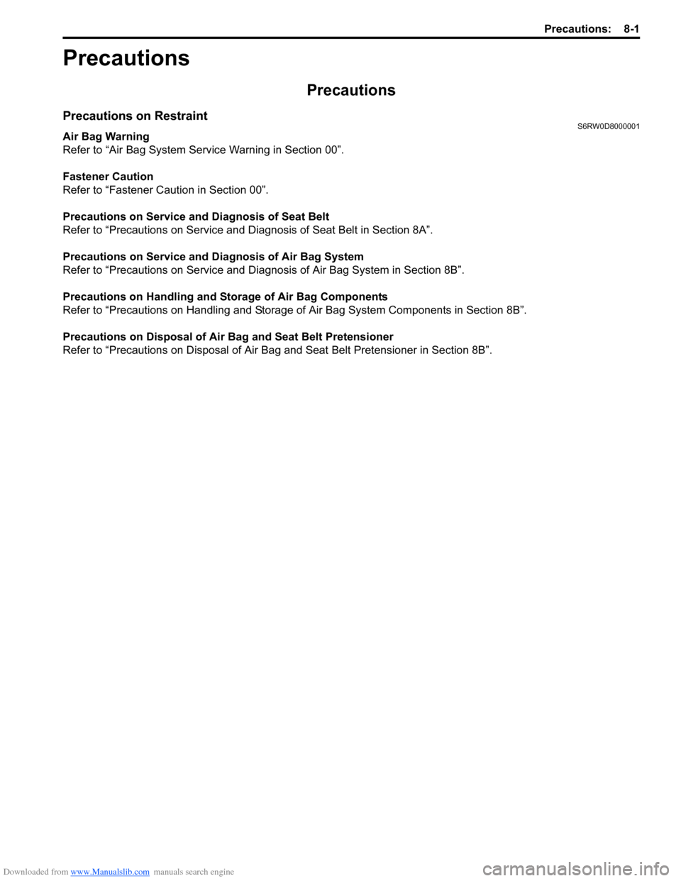
Downloaded from www.Manualslib.com manuals search engine Precautions: 8-1
Restraint
Precautions
Precautions
Precautions on RestraintS6RW0D8000001
Air Bag Warning
Refer to “Air Bag System Service Warning in Section 00”.
Fastener Caution
Refer to “Fastener Caution in Section 00”.
Precautions on Service and Diagnosis of Seat Belt
Refer to “Precautions on Service and Diagnosis of Seat Belt in Section 8A”.
Precautions on Service and Diagnosis of Air Bag System
Refer to “Precautions on Service and Diagnosis of Air Bag System in Section 8B”.
Precautions on Handling and Storage of Air Bag Components
Refer to “Precautions on Handling and Storage of Air Bag System Components in Section 8B”.
Precautions on Disposal of Air Bag and Seat Belt Pretensioner
Refer to “Precautions on Disposal of Air Bag and Seat Belt Pretensioner in Section 8B”.
Page 1032 of 1556

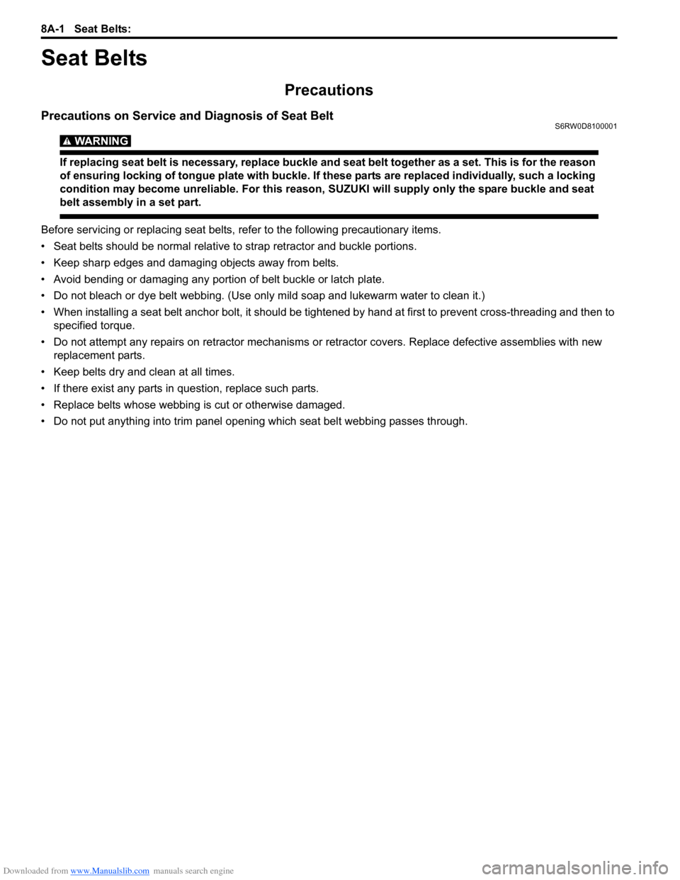
Downloaded from www.Manualslib.com manuals search engine 8A-1 Seat Belts:
Restraint
Seat Belts
Precautions
Precautions on Service and Diagnosis of Seat BeltS6RW0D8100001
WARNING!
If replacing seat belt is necessary, replace buckle and seat belt together as a set. This is for the reason
of ensuring locking of tongue plate with buckle. If these parts are replaced individually, such a locking
condition may become unreliable. For this reason, SUZUKI will supply only the spare buckle and seat
belt assembly in a set part.
Before servicing or replacing seat belts, refer to the following precautionary items.
• Seat belts should be normal relative to strap retractor and buckle portions.
• Keep sharp edges and damaging objects away from belts.
• Avoid bending or damaging any portion of belt buckle or latch plate.
• Do not bleach or dye belt webbing. (Use only mild soap and lukewarm water to clean it.)
• When installing a seat belt anchor bolt, it should be tightened by hand at first to prevent cross-threading and then to
specified torque.
• Do not attempt any repairs on retractor mechanisms or retractor covers. Replace defective assemblies with new
replacement parts.
• Keep belts dry and clean at all times.
• If there exist any parts in question, replace such parts.
• Replace belts whose webbing is cut or otherwise damaged.
• Do not put anything into trim panel opening which seat belt webbing passes through.