2006 SUBARU IMPREZA ECO mode
[x] Cancel search: ECO modePage 120 of 365
Instruments and controls 3-7
CONTINUED
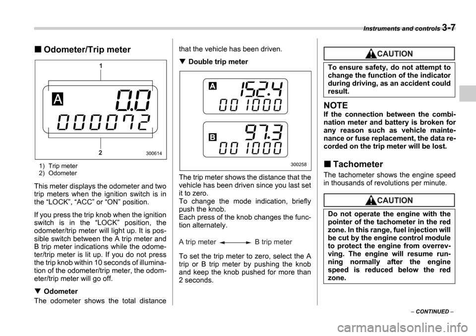
Odometer/Trip meter
1) Trip meter
2) Odometer
This meter displays the odometer and two
trip meters when the ignition switch is in
the LOCK , ACC or ON position.
If you press the trip knob when the ignition
switch is in the LOCK position, the
odometer/trip meter will light up. It is pos-
sible switch between the A trip meter and
B trip meter indications while the odome-
ter/trip meter is lit up. If you do not press
the trip knob within 10 seconds of illumina-
tion of the odometer/trip meter, the odom-
eter/trip meter will go off.
Odometer
The odometer shows the total distance that the vehicle has been driven.
Double trip meter
The trip meter shows the distance that the
vehicle has been driven since you last set
it to zero.
To change the mode indication, briefly
push the knob.
Each press of the knob changes the func-
tion alternately.
To set the trip meter to zero, select the A
trip or B trip meter by pushing the knob
and keep the knob pushed for more than
2 seconds.
NOTE
If the connection between the combi-
nation meter and battery is broken for
any reason such as vehicle mainte-
nance or fuse replacement, the data re-
corded on the trip meter will be lost.
Tachometer
The tachometer shows the engine speed
in thousands of revolutions per minute.
1
2
300614
300258
A trip meter B trip meter
To ensure safety, do not attempt to
change the function of the indicator
during driving, as an accident could
result.
Do not operate the engine with the
pointer of the tachometer in the red
zone. In this range, fuel injection will
be cut by the engine control module
to protect the engine from overrev-
ving. The engine will resume run-
ning normally after the engine
speed is reduced below the red
zone.
Page 122 of 365
Instruments and controls 3-9
CONTINUED
We recommend that you drive moderately
until the pointer of the temperature gauge
reaches near the middle of the range. En-
gine operation is optimum with the engine
coolant at this temperature range and high
revving operation when the engine is not
warmed up enough should be avoided.
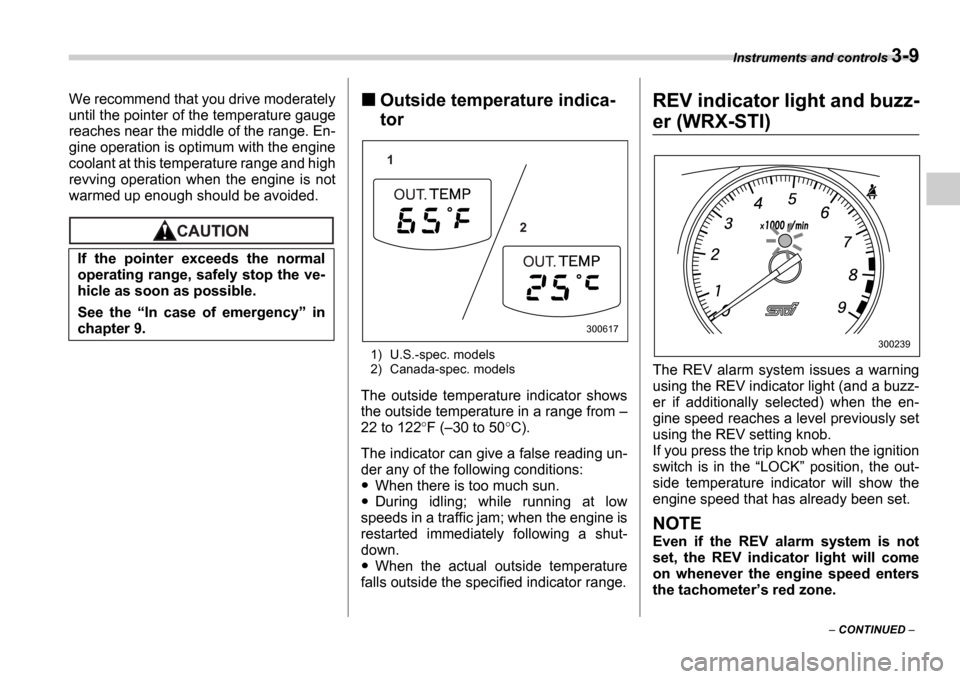
Outside temperature indica-
tor
1) U.S.-spec. models
2) Canada-spec. models
The outside temperature indicator shows
the outside temperature in a range from
22 to 122 F ( 30 to 50 C).
The indicator can give a false reading un-
der any of the following conditions:
When there is too much sun.
During idling; while running at low
speeds in a traffic jam; when the engine is
restarted immediately following a shut-
down.
When the actual outside temperature
falls outside the specified indicator range.
REV indicator light and buzz-
er (WRX-STI)
The REV alarm system issues a warning
using the REV indicator light (and a buzz-
er if additionally selected) when the en-
gine speed reaches a level previously set
using the REV setting knob.
If you press the trip knob when the ignition
switch is in the LOCK position, the out-
side temperature indicator will show the
engine speed that has already been set.
NOTE
Even if the REV alarm system is not
set, the REV indicator light will come
on whenever the engine speed enters
the tachometer s red zone.
If the pointer exceeds the normal
operating range, safely stop the ve-
hicle as soon as possible.
See the
In case of emergency in
chapter 9.
1
2
300617
300239
Page 123 of 365
3-10 Instruments and controls
Setting the alarm-level en-
gine speed
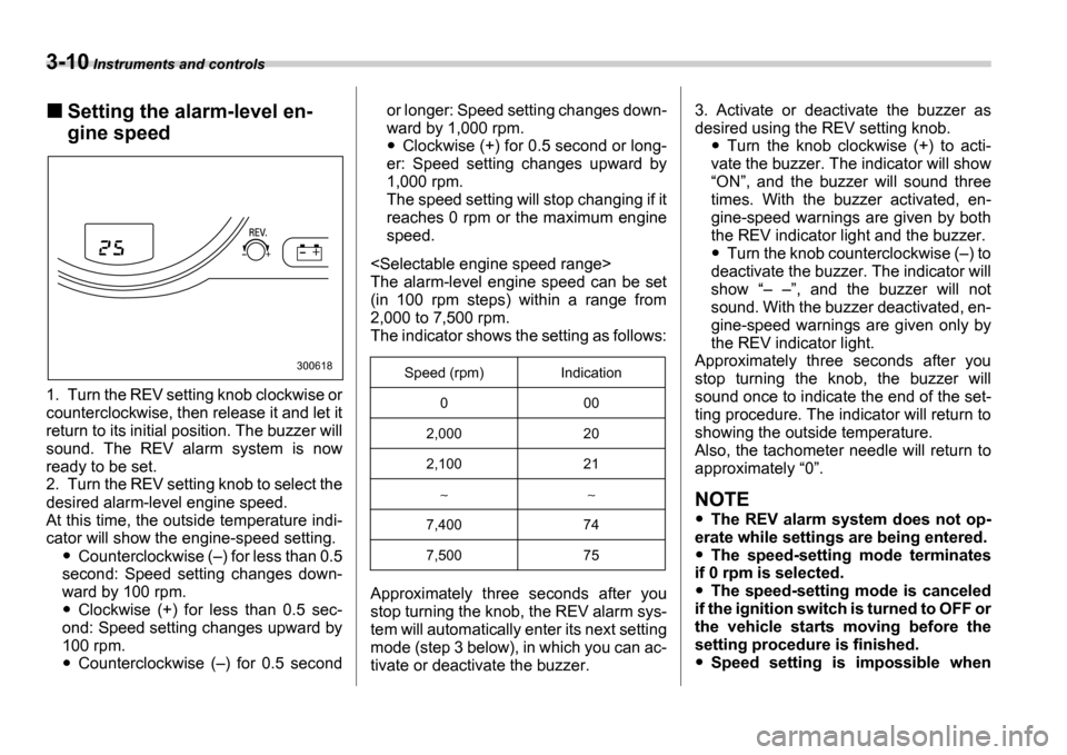
1. Turn the REV setting knob clockwise or
counterclockwise, then release it and let it
return to its initial position. The buzzer will
sound. The REV alarm system is now
ready to be set.
2. Turn the REV setting knob to select the
desired alarm-level engine speed.
At this time, the outside temperature indi-
cator will show the engine-speed setting.
Counterclockwise ( ) for less than 0.5
second: Speed setting changes down-
ward by 100 rpm.
Clockwise (+) for less than 0.5 sec-
ond: Speed setting changes upward by
100 rpm.
Counterclockwise ( ) for 0.5 second or longer: Speed setting changes down-
ward by 1,000 rpm.
Clockwise (+) for 0.5 second or long-
er: Speed setting changes upward by
1,000 rpm.
The speed setting will stop changing if it
reaches 0 rpm or the maximum engine
speed.
The alarm-level engine speed can be set
(in 100 rpm steps) within a range from
2,000 to 7,500 rpm.
The indicator shows the setting as follows:
Approximately three seconds after you
stop turning the knob, the REV alarm sys-
tem will automatically enter its next setting
mode (step 3 below), in which you can ac-
tivate or deactivate the buzzer. 3. Activate or deactivate the buzzer as
desired using the REV setting knob.Turn the knob clockwise (+) to acti-
vate the buzzer. The indicator will show ON , and the buzzer will sound three
times. With the buzzer activated, en-
gine-speed warnings are given by both
the REV indicator light and the buzzer.
Turn the knob counterclockwise ( ) to
deactivate the buzzer. The indicator will
show , and the buzzer will not
sound. With the buzzer deactivated, en-
gine-speed warnings are given only by
the REV indicator light.
Approximately three seconds after you
stop turning the knob, the buzzer will
sound once to indicate the end of the set-
ting procedure. The indicator will return to
showing the outside temperature.
Also, the tachometer needle will return to
approximately 0 .
NOTE
The REV alarm system does not op-
erate while settings are being entered.
The speed-setting mode terminates
if 0 rpm is selected.
The speed-setting mode is canceled
if the ignition switch is turned to OFF or
the vehicle starts moving before the
setting procedure is finished.
Speed setting is impossible when
300618Speed (rpm) Indication
0 00
2,000 20
2,100 21
7,400 74
7,500 75
Page 124 of 365
Instruments and controls 3-11
CONTINUED
the vehicle is moving.
The set engine speed may differ from
the engine speed shown by the ta-
chometer. Use the engine speed
shown by the tachometer as a rough
guide.
Deactivating the REV alarm
system
To deactivate the REV alarm system s
REV indicator light and buzzer functions,
set the alarm-level engine speed to 0 (ze-
ro) rpm.
Meters and gauges (Except
WRX-STI)
Speedometer
The speedometer shows the vehicle
speed.
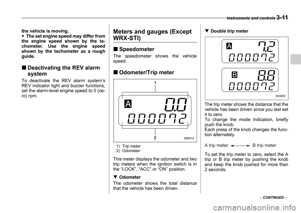
Odometer/Trip meter
1) Trip meter
2) Odometer
This meter displays the odometer and two
trip meters when the ignition switch is in
the LOCK , ACC or ON position.
Odometer
The odometer shows the total distance
that the vehicle has been driven.
Double trip meter
The trip meter shows the distance that the
vehicle has been driven since you last set
it to zero.
To change the mode indication, briefly
push the knob.
Each press of the knob changes the func-
tion alternately.
To set the trip meter to zero, select the A
trip or B trip meter by pushing the knob
and keep the knob pushed for more than
2 seconds.
1
2
300614
300660
A trip meter B trip meter
Page 126 of 365
Instruments and controls 3-13
Temperature gauge
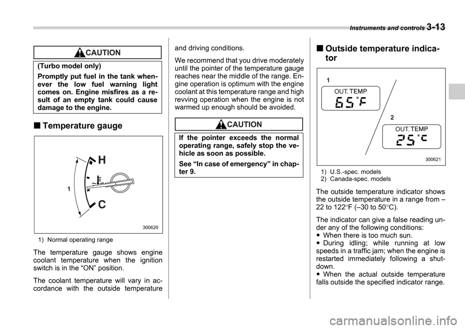
1) Normal operating range
The temperature gauge shows engine
coolant temperature when the ignition
switch is in the ON position.
The coolant temperature will vary in ac-
cordance with the outside temperature and driving conditions.
We recommend that you drive moderately
until the pointer of the temperature gauge
reaches near the middle of the range. En-
gine operation is optimum with the engine
coolant at this temperature range and high
revving operation when the engine is not
warmed up enough should be avoided.
Outside temperature indica-
tor
1) U.S.-spec. models
2) Canada-spec. models
The outside temperature indicator shows
the outside temperature in a range from
22 to 122 F ( 30 to 50 C).
The indicator can give a false reading un-
der any of the following conditions:
When there is too much sun.
During idling; while running at low
speeds in a traffic jam; when the engine is
restarted immediately following a shut-
down.
When the actual outside temperature
falls outside the specified indicator range.
(Turbo model only)
Promptly put fuel in the tank when-
ever the low fuel warning light
comes on. Engine misfires as a re-
sult of an empty tank could cause
damage to the engine.
1
300620
If the pointer exceeds the normal
operating range, safely stop the ve-
hicle as soon as possible.
See
In case of emergency in chap-
ter 9.
1
2
300621
Page 133 of 365
3-20 Instruments and controls
Selector lever position indi-
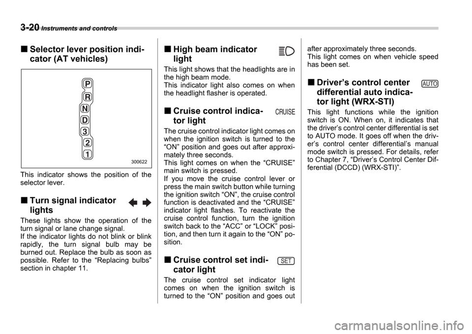
cator (AT vehicles)
This indicator shows the position of the
selector lever.
Turn signal indicator
lights
These lights show the operation of the
turn signal or lane change signal.
If the indicator lights do not blink or blink
rapidly, the turn signal bulb may be
burned out. Replace the bulb as soon as
possible. Refer to the Replacing bulbs
section in chapter 11.
High beam indicator
light
This light shows that the headlights are in
the high beam mode.
This indicator light also comes on when
the headlight flasher is operated.
Cruise control indica-
tor light
The cruise control indicator light comes on
when the ignition switch is turned to the ON position and goes out after approxi-
mately three seconds.
This light comes on when the CRUISE
main switch is pressed.
If you move the cruise control lever or
press the main switch button while turning
the ignition switch ON , the cruise control
function is deactivated and the CRUISE
indicator light flashes. To reactivate the
cruise control function, turn the ignition
switch back to the ACC or LOCK posi-
tion, and then turn it again to the ON po-
sition.
Cruise control set indi-
cator light
The cruise control set indicator light
comes on when the ignition switch is
turned to the ON position and goes out after approximately three seconds.
This light comes on when vehicle speed
has been set.
Driver
s control center
differential auto indica-
tor light (WRX-STI)
This light functions while the ignition
switch is ON. When on, it indicates that
the driver s control center differential is set
to AUTO mode. It goes off when the driv-
er s control center differential s manual
mode switch is pressed. For details, refer
to Chapter 7, Driver s Control Center Dif-
ferential (DCCD) (WRX-STI) .
300622
Page 146 of 365
Instruments and controls 3-33
CONTINUED
cover the sensors with stickers, or other
similar items. Periodically wipe the sen-
sors clean using a piece of dry soft cotton
cloth or an applicator.
Compass calibration
1. For optimum calibration, switch off all
nonessential electrical accessories (rear
window defogger, heater/air conditioning
system, spotlight, etc.) and ensure all
doors are shut.
2. Drive to an open, level area away from
large metallic objects or structures and
make certain the ignition switch is in the ON position.
3. Press and hold the left button for 3 sec-
onds then release, and the compass will
enter the calibration mode. CAL and di-
rection will be displayed.
4. Drive slowly in a circle until CAL dis-
appears from the display (approximately
two or three circles). The compass is now
calibrated.
5. Further calibration may be necessary
should outside. Influences cause the mir-
ror to read inaccurately. You will know that
this has occurred if your compass begins
to read in only limited directions. Should
you encounter this situation, return to step
one of the above procedure and recali-
brate the mirror.
Compass zone adjustment
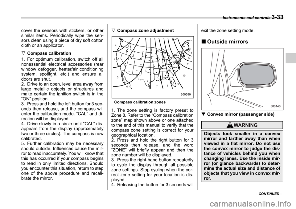
Compass calibration zones
1. The zone setting is factory preset to
Zone 8. Refer to the Compass calibration
zone map shown above or one attached
to the end of this manual to verify that the
compass zone setting is correct for your
geographical location.
2. Press and hold the right button for 3
seconds then release, and the word ZONE will briefly appear and then the
zone number will be displayed.
3. Press the right-hand button repeatedly
to cycle the display through all possible
zone settings. Stop cycling when the cor-
rect zone setting for your location is dis-
played.
4. Releasing the button for 3 seconds will exit the zone setting mode.
Outside mirrors
Convex mirror (passenger side)
10
9
8
7
6
5
4
3
1112
13
300580
Objects look smaller in a convex
mirror and farther away than when
viewed in a flat mirror. Do not use
the convex mirror to judge the dis-
tance of vehicles behind you when
changing lanes. Use the inside mir-
ror (or glance backwards) to deter-
mine the actual size and distance of
objects that you view in convex mir-
ror.
300146
Page 157 of 365
4-8 Climate control
turns on the air conditioner compres-
sor automatically and the A/C indica-
tor light on the control panel comes on.
Control panel
1) Air flow control dial
2) Fan speed control dial
3) Temperature control dial
4) Air conditioner button
5) Air inlet selection button
6) Rear window defogger button (Refer to the Rear window defogger button sec-
tion in chapter 3.)
To use as full-automatic cli-
mate control system
Place the temperature control dial in the
position for your desired temperature, then set the other dials and buttons as de-
scribed in the following. The system
s
functions will then switch to AUTO mode
and be controlled automatically.
Air flow control dial: AUTO position
Fan speed control dial: AUTO position
Air inlet selection button: Press for at
least 1 second. (Indicator will flash twice.)
Air conditioner button: Press for at least
1 second. (Indicator will flash twice.)
To use as semi-automatic cli-
mate control system
Each function can be individually set to
AUTO mode independently of the others.
Any function set to AUTO mode is con-
trolled automatically. Any function not set
to AUTO mode can be manually adjusted
as desired.
The temperature can be set within a range
of 65 to 85 F (20 to 30 C).
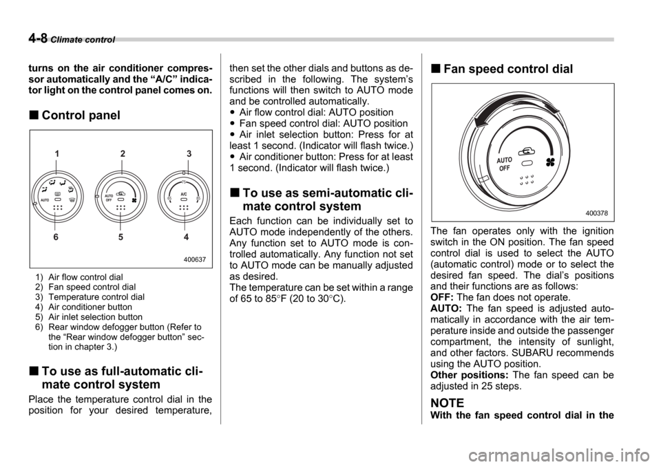
Fan speed control dial
The fan operates only with the ignition
switch in the ON position. The fan speed
control dial is used to select the AUTO
(automatic control) mode or to select the
desired fan speed. The dial s positions
and their functions are as follows:
OFF: The fan does not operate.
AUTO: The fan speed is adjusted auto-
matically in accordance with the air tem-
perature inside and outside the passenger
compartment, the intensity of sunlight,
and other factors. SUBARU recommends
using the AUTO position.
Other positions: The fan speed can be
adjusted in 25 steps.
NOTE
With the fan speed control dial in the
400637
65 85 75
1 2 3
6 5 4
400378