Page 65 of 218
 loc")
Fixing floor covering of the boot
Fig. 53
Boot: Securing the floor covering
First read and observe the introductory information and safety warn-
ings on page 60.
There is a loop or hook (Combi) located on the floor covering of the boot. If you
need to access the spare wheel, for example, the raised floor cover can be attach-
ed to a hook on the boot cover » Fig. 53 -
or to the frame of the boot lid (Com-
bi) » Fig. 53 - . ÐLuggage net
Fig. 54
Boot: Luggage net
First read and observe the introductory information and safety warn-
ings on page 60.
The luggage net is designed for the transportation of lighter objects.ä
ä WARNING
Only store soft objects in the luggage net (up to a total weight of 1.5 kg).
Heavy objects are not secured sufficiently - risk of injury! CAUTION
No objects with sharp edges should be stored in the luggage net, as they can
damage the luggage net. Ð Boot cover
Fig. 55
Removing the boot cover
First read and observe the introductory information and safety warn-
ings on page 60.
The boot cover can be removed if you wish to transport bulky goods.
›
Unhook the support straps 1
» Fig. 55.
› Place the cover in the horizontal position.
› Pull the cover out of the holders 2
horizontally towards the rear.
› To reinstall, first of all push the boot cover into the holders 2
and then hook
the support straps 1
on the boot lid.
The removed boot cover can be stowed behind the seat backrest. WARNING
No objects should be placed on the boot cover, the vehicle occupants could be
endangered if there is sudden braking or the vehicle collides with something. £
ä
63
Seats and Stowage
Page 66 of 218

CAUTION
Please ensure that the heating elements for the rear window heater are not dam-
aged as a result of objects placed in this area. Note
Opening the boot lid also lifts up the boot cover. ÐFoldable boot cover (Combi)
Fig. 56
Boot: foldable boot cover/removing foldable boot cover
First read and observe the introductory information and safety warn-
ings on page 60.
Pulling out
›
Pull the foldable luggage compartment cover in direction of arrow 1
» Fig. 56
as far as the stop into the secured position.
Folding
› Press the cover in the handle area in the direction of the arrow 2
» Fig. 56
, and
the cover automatically rolls up into position.
Removing
› The fully folded luggage compartment cover can be removed to transport bulky
goods by pressing on the side of the cross rod in the direction of the arrow 3
» Fig. 56
and taking it out by moving it in the direction of the arrow 4
.
WARNING
No objects should be placed on the foldable boot cover. Ð
ä Variable loading floor in the boot
Introductory information
The variable loading floor makes handling of bulky items of luggage easier. CAUTION
The maximum permissible load of the variable loading floor is 75 kg. Note
The room under the variable loading floor can be used to stow objects. Ð Dividing the boot with variable loading floor
Fig. 57
Boot: Dividing the boot with var-
iable loading floor
› Lift up the part with the holder and secure it by sliding it into the grooves
marked with the arrows »
Fig. 57. Ð
64 Using the system
Page 67 of 218

Removing the variable loading floor
Fig. 58
Boot: Remove variable loading floor/remove carrier rails
› Unlock the variable loading floor by turning the safety eyes A
» Fig. 58
to the
left by around 90°.
› Fold up and remove the loading floor by moving it in the direction of the arrow.
› Unlock the carrier rails B
by turning the arbour-mounted fixing eyes C
to the
right by approx. 90°. WARNING
Ensure that the carrier rails and variable loading floor are correctly fastened
when installing the variable loading floor. If this is not the case, there is a risk
of injury for the occupants. ÐNet partition (Combi)
ä
Introduction
This chapter contains information on the following subjects:
Using the net partition behind the rear seats 65
Using the net partition behind the front seats 66
Removing and installing net partition housing 66 WARNING
■ The belt locks and the belts must be in their original position after folding
back the seat cushions and backrests - they must be ready to use.
■ The seat backrests must be securely interlocked in position so that no ob-
jects in the boot can slide forwards if there is sudden braking - risk of injury!
■ Ensure that the rear seat backrests are properly engaged. It is only then that
the three-point seat belt for the middle seat can reliably fulfil its function. ■ Ensure that the cross rod is inserted into the mounts C
» Fig. 59 on
page 65 or » Fig. 60 on page 66 in the front position! Ð Using the net partition behind the rear seats
Fig. 59
Folding down the storage compartment cover/pulling out the net
partition
First read and observe the introductory information and safety warn-
ings on page 65.
Pulling out
› Fold down the storage compartment cover D
» Fig. 59 behind the rear seats.
› Pull the net partition by the bracket A
out of the housing B
in direction of the
mounts C
.
› Insert the cross rod into one of the mounts C
and push forwards.
› In the same way, insert the cross rod into the mount C
on the other side of the
vehicle.
› Fold the storage compartment cover D
downwards.
Folding
› Fold down the storage compartment cover D
» Fig. 59 behind the rear seats.
£
ä
65
Seats and Stowage
Page 68 of 218

›
First pull the cross rod back slightly on the one side and then on the other side
and remove it from the mounts C
.
› Hold the cross rod in such a way that the net partition can slowly roll up into
the housing B
without being damaged.
› Fold the storage compartment cover D
downwards.
If you wish to use the entire boot, the foldable boot cover can be re-
moved » Fig. 56 on page 64. ÐUsing the net partition behind the front seats
Fig. 60
Pull out the net partition
First read and observe the introductory information and safety warn-
ings on page 65.
Pulling out
› Fold the rear seats forward
» page 59.
› Pull the net partition by the bracket A
» Fig. 60
out of the housing B
.
› First of all insert the cross rod into the mount C
on one side and push it for-
ward.
› In the same way, insert the cross rod into the mount C
on the other side of the
vehicle.
Folding
› First pull the cross rod back slightly on the one side and then on the other side
and remove it from the mounts C
» Fig. 60
.
› Hold the cross rod in such a way that the net partition can slowly roll up into
the housing B
without being damaged.
› Fold the rear seats back into their original position. Ð
ä Removing and installing net partition housing
Fig. 61
Rear seats: Net partition hous-
ing
First read and observe the introductory information and safety warn-
ings on page 65.
Removing
› Fold the rear seats forward
»
page 59.
› Open the rear right door.
› Push the net partition housing A
» Fig. 61 in the direction of the arrow 1
and
remove it from the mounts on the rear seats in the direction of the arrow 2
.
Install
› Insert the recesses on the net partition housing into the mounts on the rear
seat backrests.
› Push the net partition housing in the opposite direction of the arrow 1
» Fig. 61 as far as the stop.
› Fold the rear seats back into their original position. Ð Roof rack system
ä
Introduction
This chapter contains information on the following subjects:
Attachment points 67
Roof load 67
£
ä
66 Using the system
Page 69 of 218

WARNING
■ The items which you transport on the roof bar system must be reliably at-
tached - risk of accident!
■ Always secure the load with appropriate and undamaged lashing straps or
tensioning straps. ■ Distribute the load evenly over the roof rack system.
■ The handling properties of your vehicle change when you transport heavy or
bulky items on the roof bar system as a result of the displacement of the cen-
tre of gravity and the increased wind attack area - risk of accident! The style
of driving and speed must therefore be adapted to the current circumstances. ■ Avoid abrupt and sudden driving/braking manoeuvres.
■ Adjust the speed and driving style to the visibility, weather, road and traffic
conditions. ■ The permissible roof load, permissible axle loads and gross permissible
weight of your vehicle must not be exceeded under any circumstances - risk
of accident! CAUTION
■ Only use roof rack systems approved by ŠKODA.
■ If other roof rack systems are used or if the roof bars are not fitted correctly,
any resulting damage to the vehicle is not covered by the warranty. It is therefore
essential that the supplied fitting instructions for the roof rack system are ob-
served.
■ On models fitted with a power sliding/tilting roof, ensure that the opened slid-
ing/tilting roof does not strike any items of luggage transported on the roof. ■ Ensure that the boot lid does not hit the roof load when opened.
■ The height of the vehicle changes after mounting a roof luggage rack system
and the load that is secured to it. Compare the vehicle height with available clear-
ances, such as underpasses and garage doors.
■ Always remove the roof luggage rack system before entering an automated car
wash. ■ Ensure the roof aerial is not impaired by the secured load. For the sake of the environment
The increased aerodynamic drag results in a higher fuel consumption. Note
If the vehicle is not factory-equipped with a roof rack, it can be purchased from
the
ŠKODA Original Accessories. Ð Attachment points
Fig. 62
Attachment points for roof bars
First read and observe the introductory information and safety warn-
ings on page 66.
Perform the assembly and disassembly according to the enclosed instructions.
CAUTION
Observe the information regarding the assembly and disassembly in the enclosed
instructions. Note
The figure only applies to Combi vehicles. Ð Roof load
First read and observe the introductory information and safety warn-
ings on page 66.
The maximum permissible roof load (including roof rack system) of
75 kg and the
maximum permissible total weight of the vehicle should not be exceeded. £
ä
ä
67
Seats and Stowage
Page 70 of 218

The full permissible roof load cannot be used if a roof rack system with a lower
load carrying capacity is used. In this case, the roof rack system must only be loa-
ded up to the maximum weight limit specified in the fitting instructions.
ÐCup holder
Fig. 63
Cup holder
Cup holder in front centre console
Two beverage containers can be placed into the recesses A
» Fig. 63.
Cup holder in rear centre console
› Press on the panel in the area B
» Fig. 63 - the cup holder comes out.
› Pull the cup holder out as far as the stop.
› Adjust the cup holder by moving the locking plate C
.
WARNING
■ Never put hot beverage containers in the cup holder. If the vehicle moves,
they may spill - risk of scalding!
■ Do not use any cups or beakers which are made of brittle material (e.g. glass,
porcelain). This could lead to injuries in the event of an accident. CAUTION
Do not leave open beverage containers in the cup holder during the journey.
There is a risk of spilling e.g. when braking which may cause damage to the elec-
trical components or seat upholstery. Ð Ashtray
Front ashtray
Fig. 64
Centre console: Opening the ashtray/ashtray insert
Opening
› Press on the bottom part of the cover of the ashtray in area A
» Fig. 64
.
Removing ashtray insert
› Press on the ashtray insert in the region B
» Fig. 64
(the insert comes out) and
take it out.
Insert ashtray insert
› Place the ashtray insert in the mount and press it in. WARNING
Never place flammable objects in the ashtray - risk of fire! Ð
68 Using the system
Page 71 of 218

Rear ashtray
Fig. 65
Rear ashtray - low centre console/high centre console
Opening the ashtray on the low centre console
› Grasp the ashtray cover at the lower edge A
» Fig. 65 and fold it open in the
direction of arrow.
Remove the ashtray from the low centre console
› Grasp the ashtray at the handle B
» Fig. 65 and remove from above.
Removing the ashtray from the low centre console
› Place the ashtray insert into the console and press it in.
Opening the ashtray on the high centre console
› Press on the top part of the ashtray cover in area C
» Fig. 65.
Removing the ashtray from the high centre console
› Lightly push the ashtray cover downwards as far as the stop.
› Grasp the ash tray insert at the cover D
» Fig. 65and remove.
Inserting the ashtray into the high centre console
› Place the ashtray insert in the mount and press it in. WARNING
Never place flammable objects in the ashtray - risk of fire! Ð Cigarette lighter, 12-volt power socket
Cigarette lighter
Fig. 66
Centre console: Cigarette lighter
Using the system › Press in the button of the cigarette lighter
» Fig. 66.
› Wait until the button pops forward.
› Remove the cigarette lighter immediately and use.
› Place the cigarette lighter back into the socket. WARNING
■ Take care when using the cigarette lighter! Improper use of the cigarette
lighter can cause burns. ■ The cigarette lighter also operates when the ignition is switched off or the
ignition key withdrawn. Therefore never leave children unattended in the ve-
hicle. Note
■ The cigarette lighter socket can also be used as a 12Volt socket for electrical ap-
pliances » page 70 , 12-volt power socket.
■ Further information » page 177, Accessories, changes and replacement of
parts. Ð
69
Seats and Stowage
Page 72 of 218

12-volt power socket
Fig. 67
Boot: Power socket
Overview of the 12-volt power socket
In the front centre console » Fig. 66 on page 69
.
In the boot » Fig. 67.
Using the power socket
› Remove the cover from power socket or cigarette lighter, or open the cover for
the power socket.
› Connect the plug for the electrical appliance to the socket.
Further information » page 177, Accessories, changes and replacement of parts .WARNING
■ Improper use of the 12-volt power socket and the electrical accessories can
cause fires, burns and other serious injuries. ■ Never leave children unattended in the vehicle. The 12-volt power socket
and any connected appliances can also be operated when the ignition is
switched off or the ignition key is withdrawn. ■ If the connected electric device becomes too hot, switch it off and discon-
nect it from the power supply immediately. CAUTION
■ Never exceed the maximum power consumption, otherwise the vehicle's elec-
trical system can be damaged.
■ Connecting electrical components when the engine is not running will drain the
battery of the vehicle - risk of battery draining!
■ Only use matching plugs to avoid damaging the 12-volt power socket. ■
Only use accessories that have been tested for electromagnetic compatibility in
accordance with the applicable directives.
■ Before turning the ignition on or off, and before starting the car, switch off the
device connected to the 12-volt power socket to prevent any damage caused by
voltage fluctuations.
■ Observe the operating instructions for the connected devices! Note
The 12-volt power socket can only be used for connecting approved electrical ac-
cessories with a total power uptake of up to 120
watt.Ð Storage compartments
Overview
The vehicle has the following storage compartments: Storage compartment on the front passenger side » page 71
Storage compartment on the driver's side » page 71
Storage compartment on the dash panel » page 72
Stowage compartment in front centre console » page 72
Storage net in the front centre console » page 72
Map pockets in the front seats » page 73
Glasses storage box » page 73
Storage compartments in the doors » page 73
Stowage compartment below front passenger seat » page 74
Front armrest with storage compartment » page 74
Rear armrest with storage compartment » page 75
Stowage compartment in rear centre console » page 75
Seat backrest with through-loading channel » page 75
Removable through-loading bag » page 76
Side compartment in the luggage compartment » page 77
Stowage compartment behind the rear seats (Estate
car) » page 77
£70
Using the system
 1
1 2
2 3
3 4
4 5
5 6
6 7
7 8
8 9
9 10
10 11
11 12
12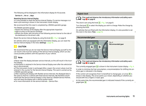 13
13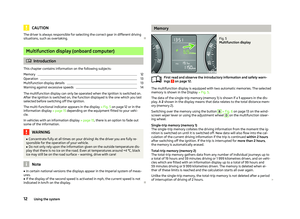 14
14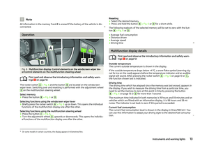 15
15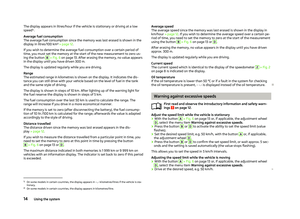 16
16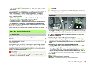 17
17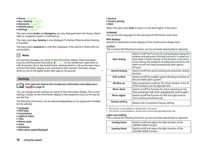 18
18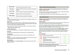 19
19 20
20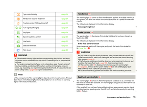 21
21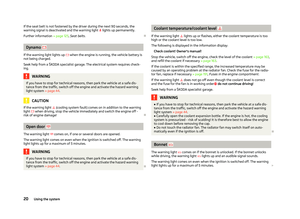 22
22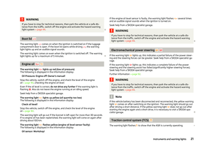 23
23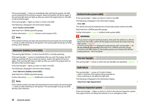 24
24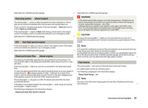 25
25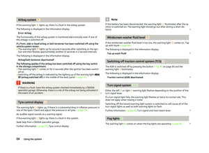 26
26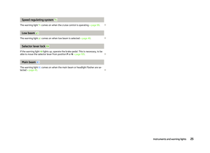 27
27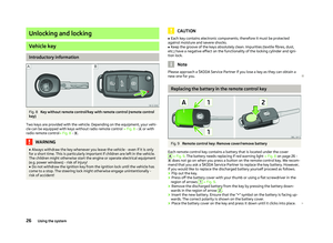 28
28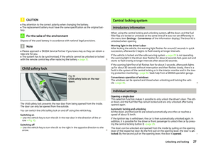 29
29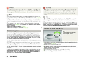 30
30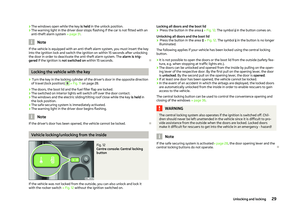 31
31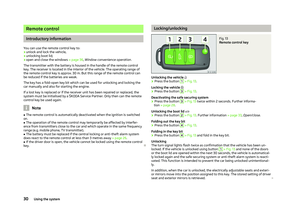 32
32 33
33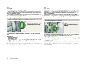 34
34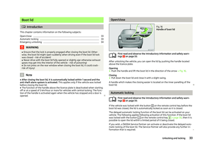 35
35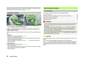 36
36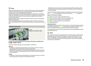 37
37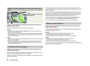 38
38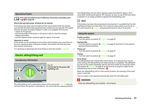 39
39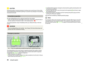 40
40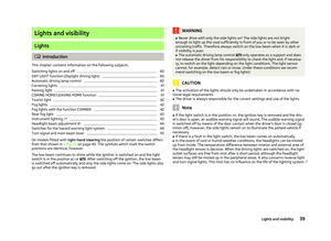 41
41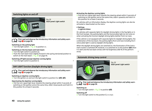 42
42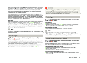 43
43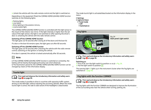 44
44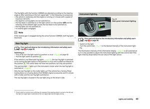 45
45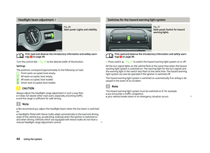 46
46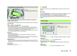 47
47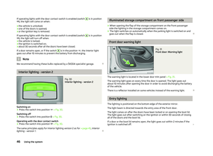 48
48 49
49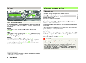 50
50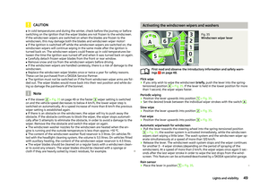 51
51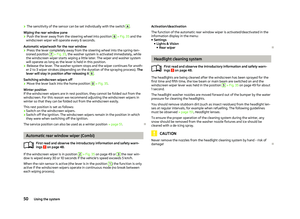 52
52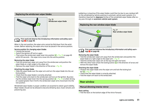 53
53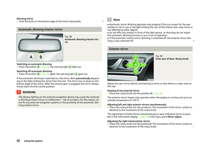 54
54 55
55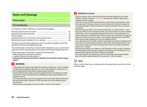 56
56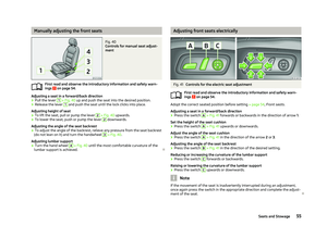 57
57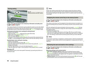 58
58 59
59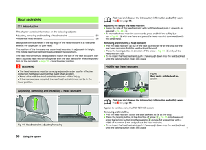 60
60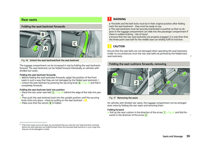 61
61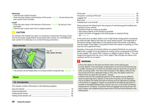 62
62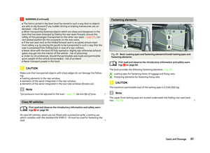 63
63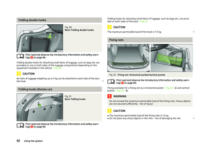 64
64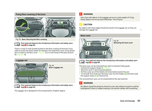 65
65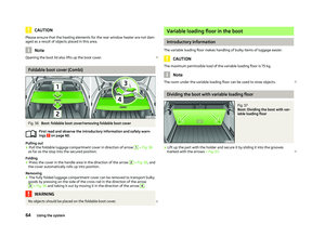 66
66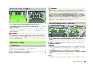 67
67 68
68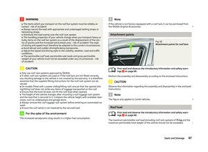 69
69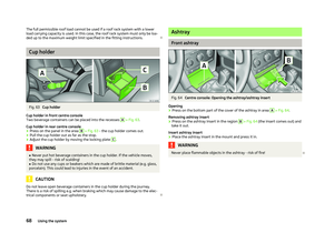 70
70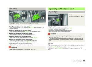 71
71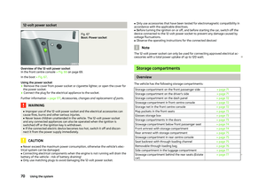 72
72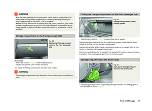 73
73 74
74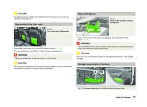 75
75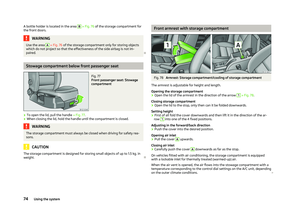 76
76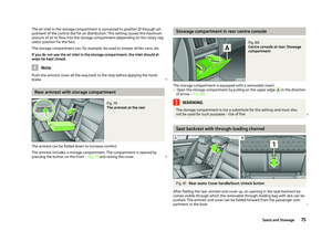 77
77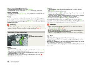 78
78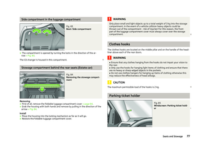 79
79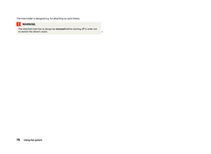 80
80 81
81 82
82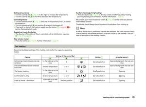 83
83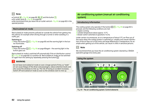 84
84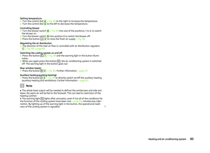 85
85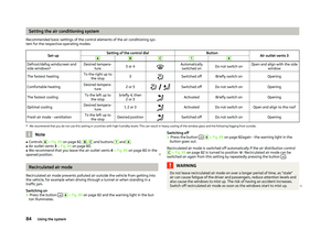 86
86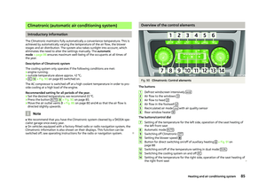 87
87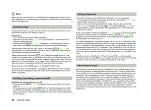 88
88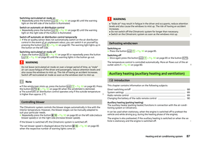 89
89 90
90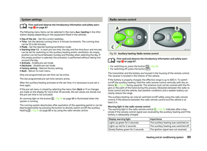 91
91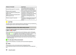 92
92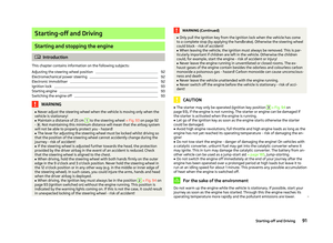 93
93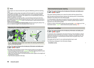 94
94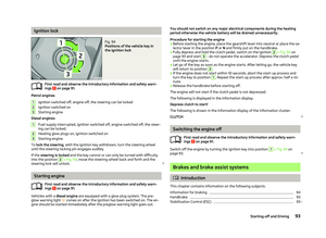 95
95 96
96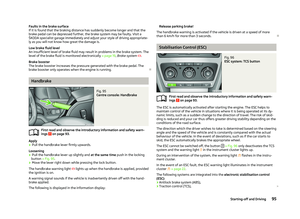 97
97 98
98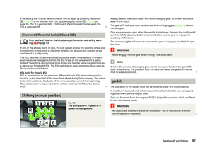 99
99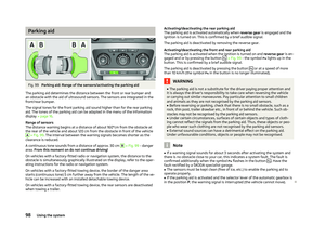 100
100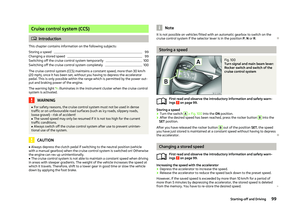 101
101 102
102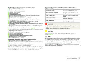 103
103 104
104 105
105 106
106 107
107 108
108 109
109 110
110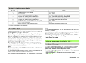 111
111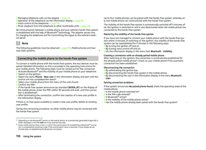 112
112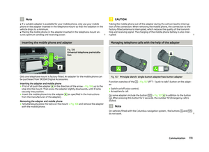 113
113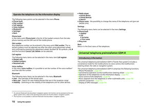 114
114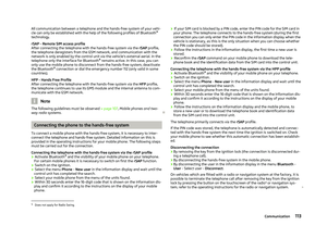 115
115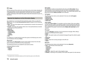 116
116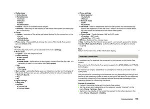 117
117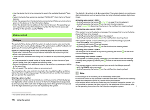 118
118 119
119 120
120 121
121 122
122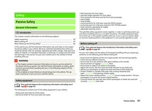 123
123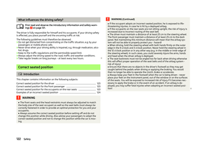 124
124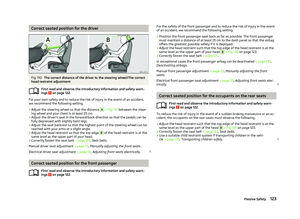 125
125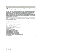 126
126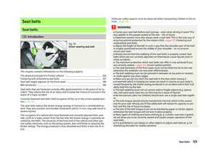 127
127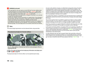 128
128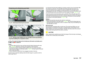 129
129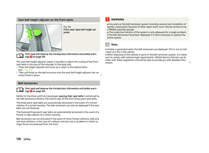 130
130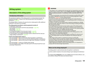 131
131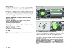 132
132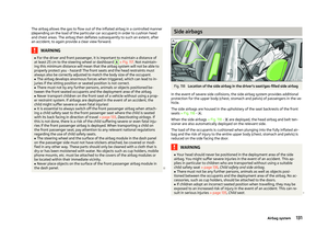 133
133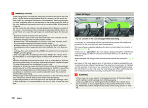 134
134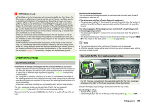 135
135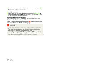 136
136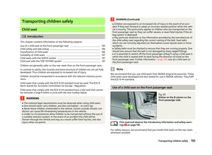 137
137 138
138 139
139 140
140 141
141 142
142 143
143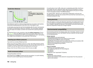 144
144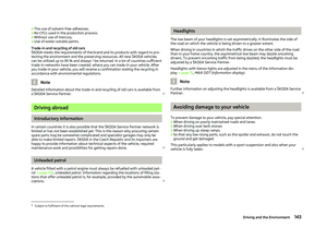 145
145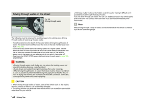 146
146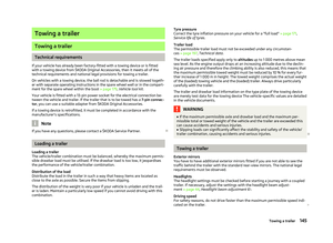 147
147 148
148 149
149 150
150 151
151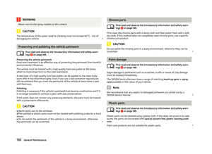 152
152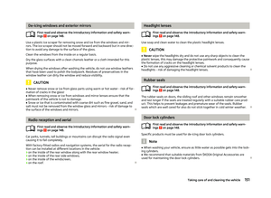 153
153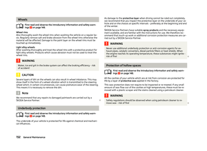 154
154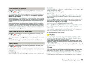 155
155 156
156 157
157 158
158 159
159 160
160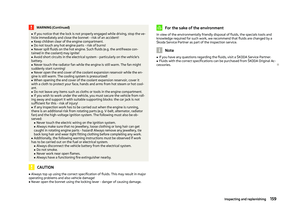 161
161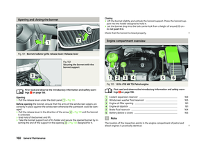 162
162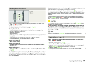 163
163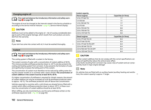 164
164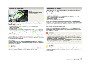 165
165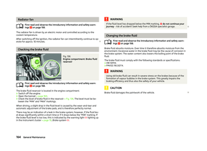 166
166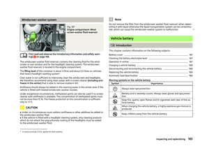 167
167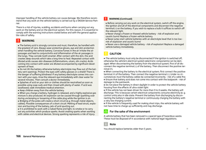 168
168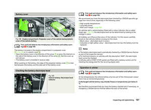 169
169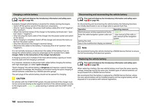 170
170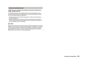 171
171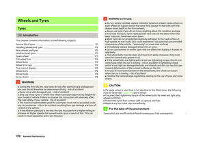 172
172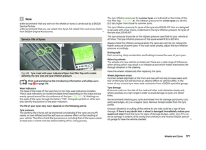 173
173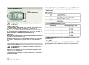 174
174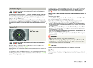 175
175 176
176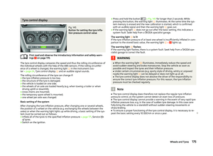 177
177 178
178 179
179 180
180 181
181 182
182 183
183 184
184 185
185 186
186 187
187 188
188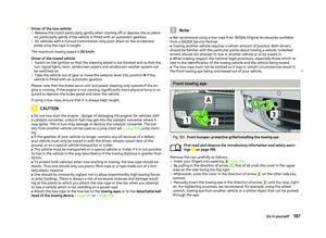 189
189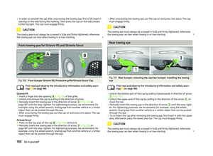 190
190 191
191 192
192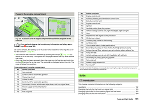 193
193 194
194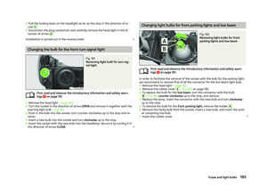 195
195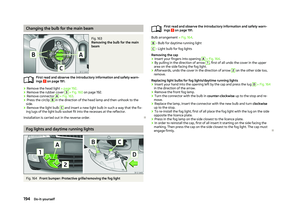 196
196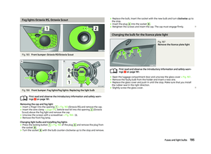 197
197 198
198 199
199 200
200 201
201 202
202 203
203 204
204 205
205 206
206 207
207 208
208 209
209 210
210 211
211 212
212 213
213 214
214 215
215 216
216 217
217