Page 193 of 218

Fuses in the engine compartment
Fig. 159
Fuse box cover in engine compartment/Schematic diagram of the
fuse box
First read and observe the introductory information and safety warn-
ings on page 189.
On some vehicles, the battery cover must be removed before removing the cover
for the fuse box
» page 167.
› The cover for the fuse box is removed by pushing the circlips A
» Fig. 159
up-
wards as far as the stop. The symbol is displayed behind the clip. Now remove
the cover.
› Once the fuse has been removed, place the cover on the fuse box and push the
circlips A
back as far as the stop. The symbol
is displayed behind the clip. The
cover is locked into position.
Fuse assignment in engine compartment No. Power consumer
F1 Not assigned
F2 Control unit for automatic gearbox
F3 Measuring circuit
F4 Valves for ABS F5 Control unit for automatic gearbox
F6 Instrument cluster, windscreen wiper lever, and turn signal lever F7 Power supply terminal 15, Starter
F8 Radio F9 Not assigned ä
No. Power consumer
F10 Engine control unit F11 Auxiliary heating and ventilation control unit
F12 Data bus control unit
F13 Engine control unit
F14 Ignition F15 Lambda probe, glow plug system
F16 Vehicle voltage control unit, right headlight, right tail light F17 Horn
F18 Amplifier for the digital sound processor F19 Windscreen wipers
F20 Coolant pump, valve for fuel dosing F21 Lambda probe
F22 Clutch pedal switch, brake pedal switch
F23 Secondary air pump, air mass meter, fuel high pressure pump
F24 Active charcoal filter, exhaust gas recirculation valve, radiator fan F25 Pump for ABS
F26 Vehicle voltage control unit, left headlight, left tail light F27 Secondary air pump, glow plug system
F28 Not assigned F29 Power supply terminal 30
F30 Terminal X a) a)
In order not to drain the battery unnecessarily when starting the engine, the electrical components
of this terminal are automatically switched off. Ð Bulbs
ä
Introduction
This chapter contains information on the following subjects:
Headlights 192
Changing the bulb for the front turn signal light 193
Changing light bulbs for front parking lights and low beam 193
Changing the bulb for the main beam 194
£
191
Fuses and light bulbs
Page 194 of 218
 196
Some manual skills ar")
Fog lights and daytime running lights 194
Fog lights Octavia RS, Octavia Scout 195
Changing the bulb for the licence plate light 195
Tail lamp assembly 196
Tail light (Combi) 196
Some manual skills are required to change a bulb. For this reason, if uncertain, we
recommend that bulbs are replaced by a ŠKODA specialist garage or other expert
help is sought.
› Switch off the ignition and all of the lights before replacing a bulb.
› Faulty bulbs must only be replaced with the same type of bulbs. The designa-
tion is located on the light socket or the glass bulb.
› A stowage compartment for replacement bulbs is located in a plastic box in the
spare wheel or underneath the floor covering in the boot. WARNING
■ Accidents can be caused if the road in front of the vehicle is not sufficiently
illuminated and the vehicle cannot or can only be seen with difficulty by other
road users.
■ Always read and observe the warnings before completing any work in the
engine compartment »
page 158, Engine compartment .
■ Bulbs H7 and H1 are pressurised and may burst when changing the bulb -
risk of injury! We therefore recommended wearing gloves and safety glasses
when changing a bulb. ■ Gas discharge bulbs (xenon bulbs) operate with a high voltage, professional
knowledge is required - danger to life! CAUTION
■ Do not take hold of the glass bulb with naked fingers (even the smallest
amount of dirt reduces the working life of the light bulb). Use a clean cloth, nap-
kin, or similar. ■ When removing and installing the headlight make sure that the paintwork of
the vehicle and the headlight are not damaged. Note
■ This Owner's Manual only describes the replacement of bulbs where it is possi-
ble to replace the bulbs on your own without any complications arising. Other
light bulbs should be changed by a
ŠKODA specialist garage.
■ We recommend that a box of replacement bulbs be always carried in the vehi-
cle. Replacement bulbs can be purchased from
ŠKODAOriginal Accessories.
■ We recommend that the headlight settings are checked by a ŠKODA specialist
garage after replacing a bulb in the main or low beam.
■ Gas discharge bulbs and LED diodes are replaced by a ŠKODA specialist garage. Ð Headlights
Fig. 160
Headlights: Bulb arrangement/removal
First read and observe the introductory information and safety warn-
ings on page 191.
Overview of the location of the bulbs
» Fig. 160. 1
- front turn signal light
2
- parking lights and low beam
3
- main beam light
The headlight must be removed in order to change the light bulb of the parking
lights, low beam lights and main beam lights as well as the turn signal lights.
Removing the main beam lights
› Open the bonnet
» page 160, Opening and closing the bonnet .
› Unscrew the plastic nuts A
» Fig. 160
.
› Pull the locking button B
upwards.
£
ä
192 Do-it-yourself
Page 195 of 218

›
Pull the locking lever on the headlight as far as the stop in the direction of ar-
row C
.
› Disconnect the plug connection and carefully remove the head light in the di-
rection of arrow D
.
Installation is carried out in the reverse order. ÐChanging the bulb for the front turn signal light
Fig. 161
Removing light bulb for turn sig-
nal light
First read and observe the introductory information and safety warn-
ings on page 191.
›
Remove the head light
» page 192.
› Turn the socket in the direction of arrow
OPEN and remove it together with the
warning light bulb » Fig. 161.
› Push in the bulb into the socket, turn counter-clockwise up to the stop and re-
move.
› Insert a new bulb into the socket and turn
clockwise up to the stop.
› Insert the socket with the new bulb into the headlamp. Secure it by turning it in
the direction of arrow CLOSE. Ð
ä Changing light bulbs for front parking lights and low beam
Fig. 162
Removing light bulbs for front
parking lights and low beam
First read and observe the introductory information and safety warn-
ings on page 191.
In order to facilitate the removal of the socket with the bulb for the parking light,
we recommend to remove first of all the connector for the low beam light bulb.
›
Remove the head light
» page 192.
› Remove the rubber cover 2
» Fig. 160
on page 192.
› To replace the bulb for the
low beam, turn the connector with the bulb B
» Fig. 162 counter-clockwise
up to the stop, and remove.
› Replace the lamp, insert the connector with the new bulb and turn
clockwise
up to the stop.
› To remove the bulb for the
front parking light, remove the holder A
.
› Remove the faulty bulb from the socket, insert a new bulb, and insert the sock-
et containing the bulb.
› Insert the rubber cover. Ð
ä
193
Fuses and light bulbs
Page 196 of 218

Changing the bulb for the main beam
Fig. 163
Removing the bulb for the main
beam
First read and observe the introductory information and safety warn-
ings on page 191.
›
Remove the head light
» page 192.
› Remove the rubber cover 3
» Fig. 160
on page 192.
› Remove connector A
» Fig. 163.
› Press the circlip B
in the direction of the head lamp and then unhook to the
side.
› Remove the light bulb C
and insert a new light bulb in such a way that the fix-
ing lugs of the light bulb socket fit into the recesses at the reflector.
Installation is carried out in the reverse order. ÐFog lights and daytime running lights
Fig. 164
Front bumper: Protective grille/removing the fog light
ä
First read and observe the introductory information and safety warn-
ings on page 191.
Bulb arrangement
» Fig. 164. B
- Bulb for daytime running light
C
- Light bulb for fog lights
Removing the cap
› Insert your fingers into opening A
» Fig. 164 .
› By pulling in the direction of arrow 1
, first of all undo the cover in the upper
area on the side facing the fog light.
› Afterwards, undo the cover in the direction of arrow 2
on the other side too,
remove.
Replacing light bulbs for fog lights/daytime running lights
› Insert your hand into the opening left by the cap and press the lug D
»
Fig. 164
in the direction of the arrow.
› Remove the front fog lamp.
› Turn the connector with the bulb in
counter-clockwise up to the stop and re-
move.
› Replace the lamp, insert the connector with the new bulb and turn
clockwise
up to the stop.
› To re-install the fog light, first of all place the fog light with the lug on the side
opposite the licence plate.
› Press in the fog lamp on the side closest to the licence plate.
› In order to reinstall the cap, first of all insert it starting on the side facing the
marking. Then press the cap on the side closest to the fog light. The cap must
engage firmly. Ð
ä
194 Do-it-yourself
Page 197 of 218

Fog lights Octavia RS, Octavia Scout
Fig. 165
Front bumper: Octavia RS/Octavia Scout Fig. 166
Front bumper: Fog lights/fog lights: Replacing the light bulb
First read and observe the introductory information and safety warn-
ings on page 191.
Removing the cap and fog light
›
Insert a finger into the opening 1
» Fig. 165 (Octavia RS) and remove the cap.
› Insert the wire clamp
» page 179, Vehicle tool kit into the opening 2
(Octavia
Scout) above the fog light and remove the cap.
› Unscrew the screws with a screwdriver
» Fig. 166 - .
› Remove the front fog lamp.
Changing light bulbs and installing fog lights
› Press the locking button 1
» Fig. 166
of the plug A
and remove the plug from
the socket B
.
› Turn the socket B
with the bulb counter-clockwise up to the stop and remove.
ä ›
Replace the bulb, insert the socket with the new bulb and turn
clockwise up to
the stop.
› Insert the plug A
into the socket B
.
› Retighten the screws and insert the cap. The cap must engage firmly. Ð Changing the bulb for the licence plate light
Fig. 167
Remove the licence plate light
First read and observe the introductory information and safety warn-
ings on page 191.
›
Open the luggage compartment door and unscrew the glass cover
» Fig. 167.
› Remove the faulty bulb from the holder and insert a new one.
› Replace the glass cover and push in until the stop. Make sure that you install
the rubber seal in the right direction.
› Slightly screw the glass cover. Ð
ä
195
Fuses and light bulbs
Page 198 of 218

Tail lamp assembly
Fig. 168
Boot: Cover of the lamp holder/removing the lamp holder
First read and observe the introductory information and safety warn-
ings on page 191.
Replacing the light bulbs in the lamp holder
›
Unlock the cover of the lamp holder, open
» Fig. 168 - .
› Press the catches in the direction of the arrow and remove the lamp hold-
er » Fig. 168 - .
› Push in the bulb into the socket, turn counter-clockwise up to the stop and re-
move.
› Insert a new bulb into the socket and turn
in a clockwise direction to the the
stop.
› Replace the lamp holder so that the catches engage in the housing of the tail
light.
› Close and lock the cover of the lamp holder.
Change the light bulb for the parking light
› Unlock the cover of the lamp holder, open
» Fig. 168 - .
› Remove the faulty light bulb (arrow 1
or 2
) from the housing of the tail light,
replace, and re-insert.
› Close and lock the cover of the lamp holder. Ð
ä Tail light (Combi)
Fig. 169
Boot: Cover of the lamp holder/removing the lamp holder
First read and observe the introductory information and safety warn-
ings on page 191.
Replacing the light bulbs in the lamp holder
›
Open the lamp holder cover
» Fig. 169 - .
› Remove the bulbs for the parking lights (arrow 1
and 2
).
› Press the catch in the direction of the arrow and remove the lamp hold-
er » Fig. 169 - .
› Push in the bulb into the socket, turn counter-clockwise up to the stop and re-
move.
› Insert a new bulb into the socket and turn
in a clockwise direction to the the
stop.
› Replace the lamp holder so that the catch engages in the housing of the tail
light.
› Reinsert the bulbs for the parking lights (arrow 1
and 2
).
› Close the lamp holder cover.
Change the light bulb for the parking light
› Open the lamp holder cover
» Fig. 169 - .
› Remove the faulty light bulb (arrow 1
or 2
) from the housing of the tail light,
replace, and re-insert.
› Close the lamp holder cover. Ð
ä
196 Do-it-yourself
Page 199 of 218

Technical data
Technical data
Introductory information
The details given in the vehicle's technical documentation always take prece-
dence over the details in the Owner's Manual. Please refer to the official vehicle
registration documents or consult a
ŠKODA Service Partner to determine which
engine your vehicle is equipped with.
The listed performance values were determined without performance-reducing
equipment, e.g. air conditioning system.
Vehicle identification number (VIN)
The vehicle identification number - VIN (vehicle body number) is stamped into the
engine compartment on the right hand suspension strut dome. This number is al-
so located on a sign on the lower left hand edge below the windscreen (together
with a VIN bar code).
Engine number
The engine number is stamped into the engine block. ÐData on the vehicle data sticker and the type plate
Fig. 170
Vehicle data sticker/type plate Vehicle data sticker
The vehicle data sticker
» Fig. 170 is located on the floor of the boot and is also
stated in the service schedule.
The vehicle data sticker contains the following data:
Vehicle identification number (VIN)
Vehicle type
Gearbox code/paint number/interior equipment/engine output/engine code
Partial vehicle description
Operating weight (in kg)
Fuel consumption (in ltr./100
km) - intra-urban/extra-urban/combined
CO 2 emission levels - combined (in g/km)
Type plate
The type plate » Fig. 170 is located on the lower part of the column between the
front and rear doors on the driver's side.
The type plate lists the following weights:
Maximum permissible gross weight
Maximum permissible towed weight (towing vehicle and trailer)
Maximum permissible front axle load
Maximum permissible rear axle load
Operating weight
The specified operating weight is for orientation purposes only. This value repre-
sents the minimum operating weight without additional weight-increasing equip-
ment such as air conditioning system, spare wheel, or trailer hitch.
The operating weight also contains the weight of the driver (75 kg), the weight of
the operating fluids, the tool kit, and a fuel tank filled to 90 % capacity.
It is possible to calculate the approximate loading capacity from the difference
between the permissible total weight and the operating weight » .
The payload consists of the following components:
› Passengers
› All items of luggage and other loads
› Roof load including roof rack system
› Equipment not included in the operating weight
› Trailer drawbar load when towing a trailer (max. 80 kg).
£ 1
2
3
4
5
6
7
8
9
10
11
197
Technical data
Page 200 of 218

Measuring the fuel consumption and CO
2 emissions according to the ECE
standards and EU guidelines
The measurement of the intra-urban cycle begins with a cold start of the engine.
Afterwards urban driving is simulated.
In the extra-urban driving cycle, the vehicle is accelerated and decelerated in all
gears, corresponding to daily routine driving conditions. The driving speed varies
between 0 and 120 km/h.
The calculation of the combined fuel consumption considers a weighting of about
37 % for the intra-urban cycle and 63 % for the extra-urban cycle. WARNING
Do not exceed the specified maximum permissible weights - risk of accident
and damage. Note
■ If required, you can find out the precise weight of your vehicle by contacting a
ŠKODA
Service Partner.
■ Depending on the range of equipment, style of driving, traffic situation, weather
influences and vehicle condition, consumption values may deviate from the indi-
cated values. ÐDimensions
Dimensions (mm) OCTAVIAOCTAVIA
GreenLine OCTAVIA RS ESTATE ESTATE
GreenLine ESTATE RS COMBI 4x4 SCOUT
Length 4569
4597 a)
4569
45974569
4584 b)
4569 4599 4569 4584
Width 1769176917691769
1784 b)
1769 1769 1769 1784
Width including exterior mirror 201820182018 2018 2018 2018 2018 2018
Height 1462
1485 c)
1449 d)
1484 a) 1462
1449 d)
1447 1468
1490 c)
1455 d)
1501 b) 1468
1455 d)
1451 1495
1520 c)
1533
Clearance 140
164 c)
125 d) 140
125 d)
127 140
164 c)
125 d)
179 b) 140
125 d)
128 138
163 c)
179
£198
Technical data
 1
1 2
2 3
3 4
4 5
5 6
6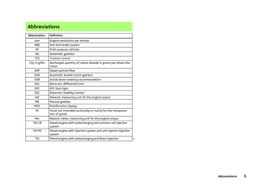 7
7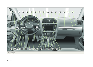 8
8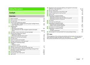 9
9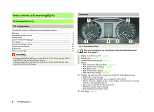 10
10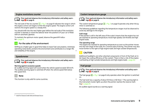 11
11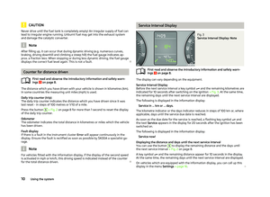 12
12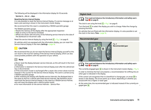 13
13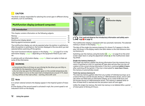 14
14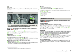 15
15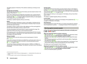 16
16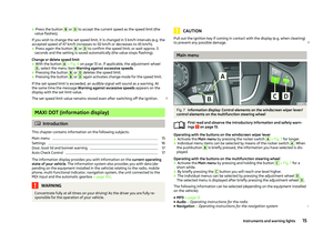 17
17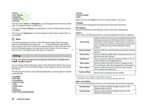 18
18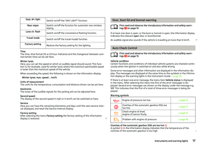 19
19 20
20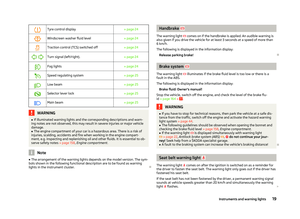 21
21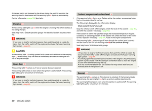 22
22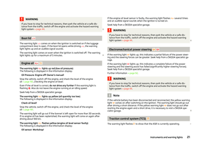 23
23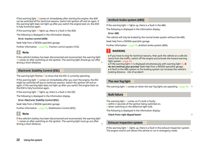 24
24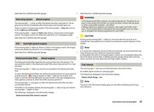 25
25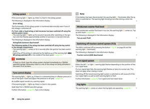 26
26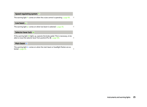 27
27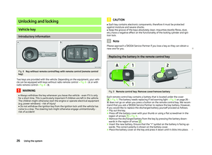 28
28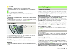 29
29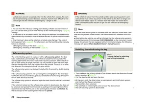 30
30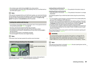 31
31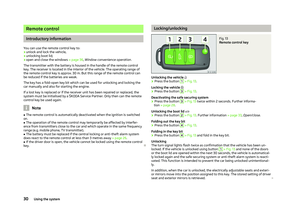 32
32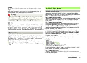 33
33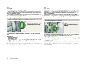 34
34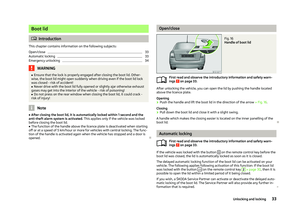 35
35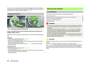 36
36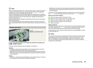 37
37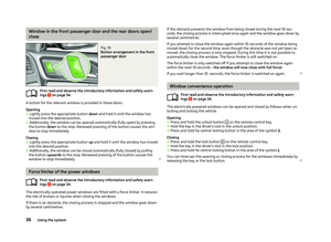 38
38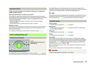 39
39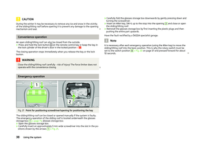 40
40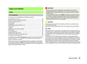 41
41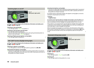 42
42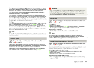 43
43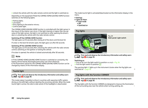 44
44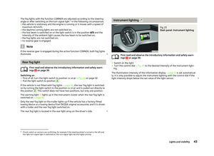 45
45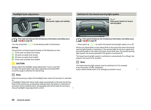 46
46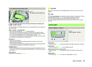 47
47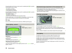 48
48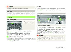 49
49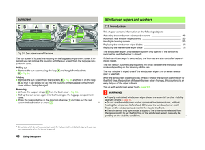 50
50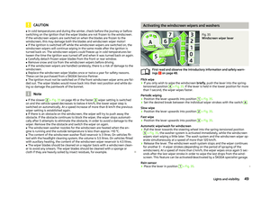 51
51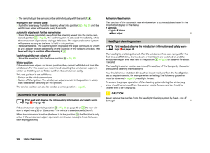 52
52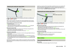 53
53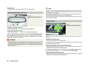 54
54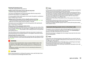 55
55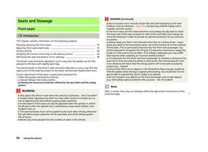 56
56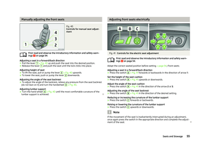 57
57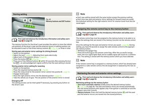 58
58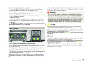 59
59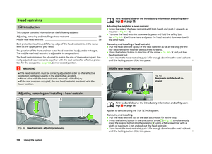 60
60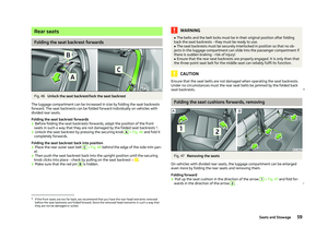 61
61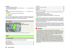 62
62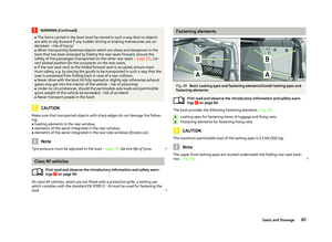 63
63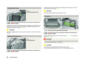 64
64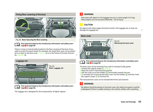 65
65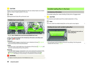 66
66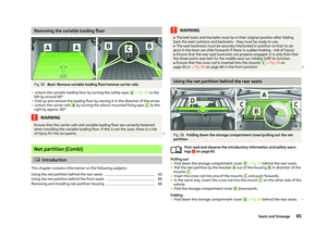 67
67 68
68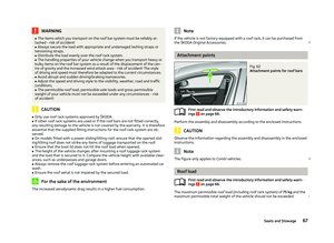 69
69 70
70 71
71 72
72 73
73 74
74 75
75 76
76 77
77 78
78 79
79 80
80 81
81 82
82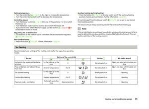 83
83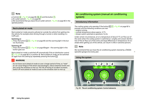 84
84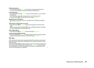 85
85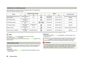 86
86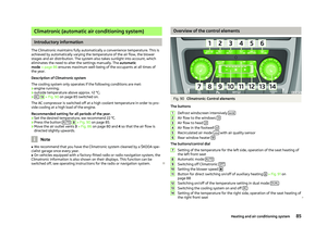 87
87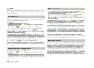 88
88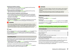 89
89 90
90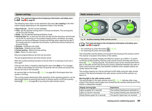 91
91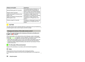 92
92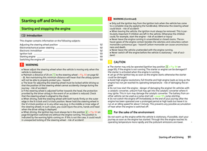 93
93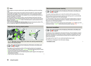 94
94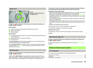 95
95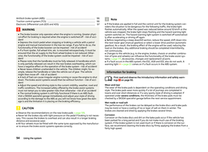 96
96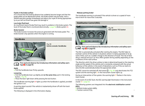 97
97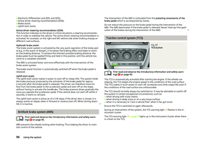 98
98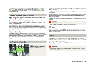 99
99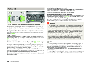 100
100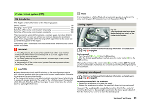 101
101 102
102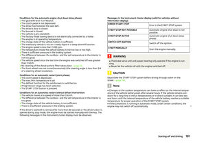 103
103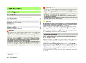 104
104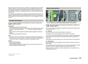 105
105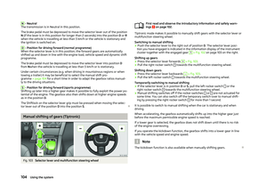 106
106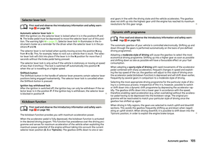 107
107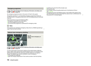 108
108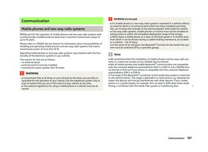 109
109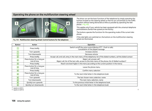 110
110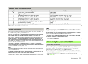 111
111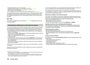 112
112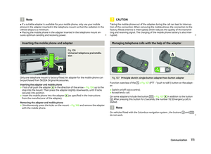 113
113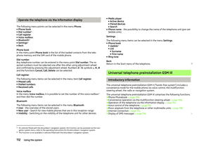 114
114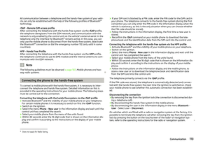 115
115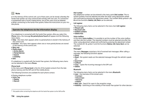 116
116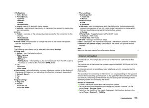 117
117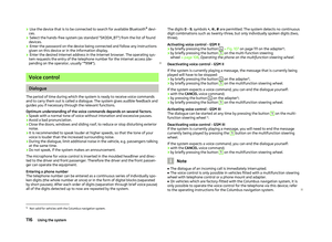 118
118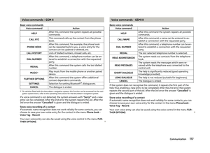 119
119 120
120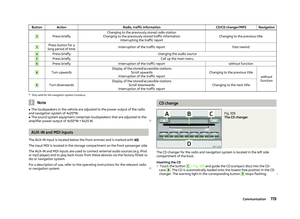 121
121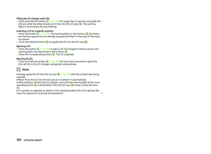 122
122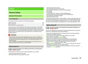 123
123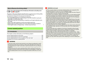 124
124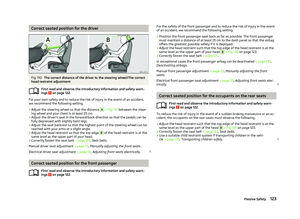 125
125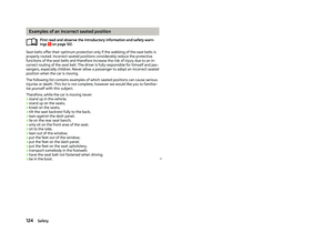 126
126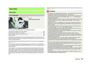 127
127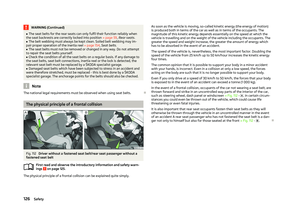 128
128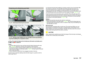 129
129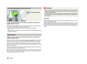 130
130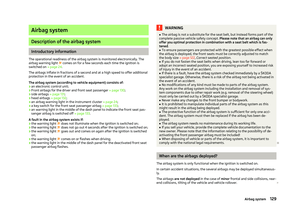 131
131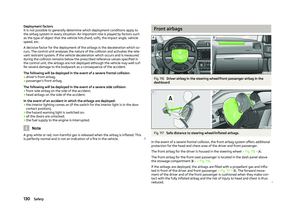 132
132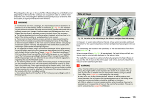 133
133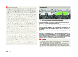 134
134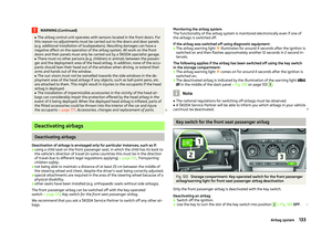 135
135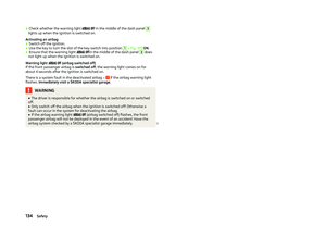 136
136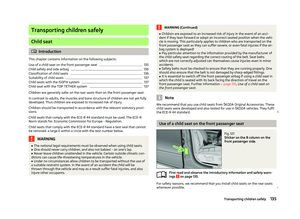 137
137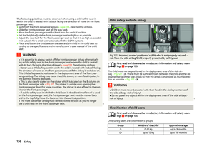 138
138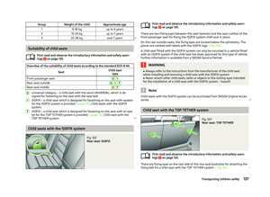 139
139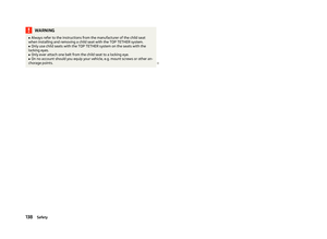 140
140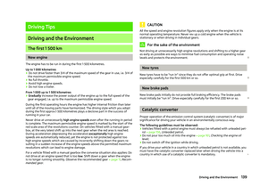 141
141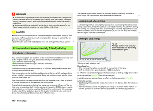 142
142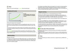 143
143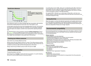 144
144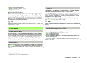 145
145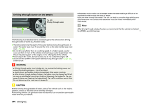 146
146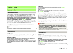 147
147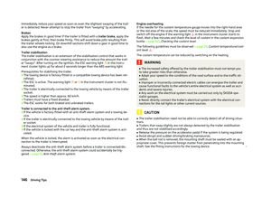 148
148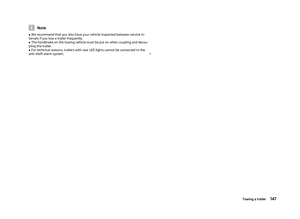 149
149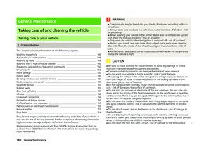 150
150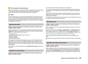 151
151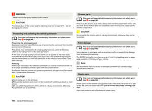 152
152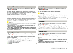 153
153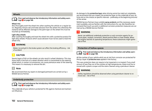 154
154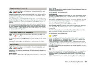 155
155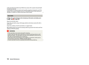 156
156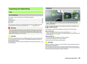 157
157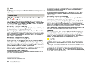 158
158 159
159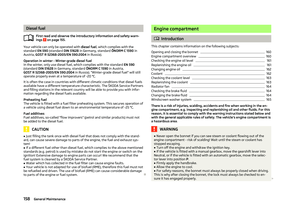 160
160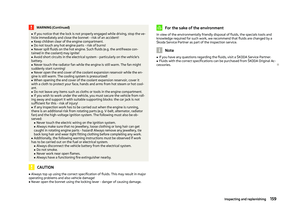 161
161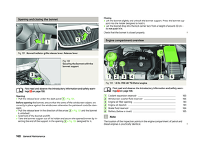 162
162 163
163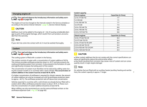 164
164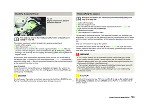 165
165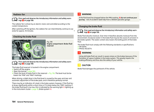 166
166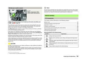 167
167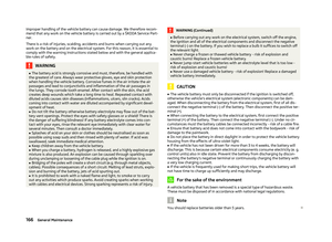 168
168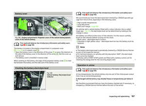 169
169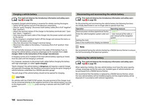 170
170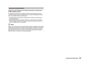 171
171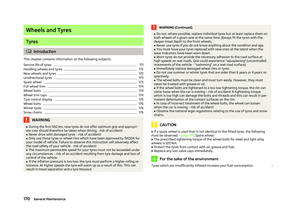 172
172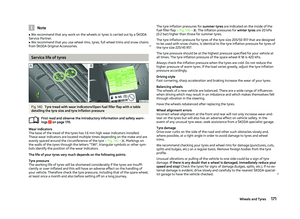 173
173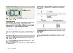 174
174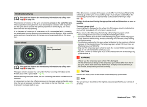 175
175 176
176 177
177 178
178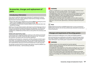 179
179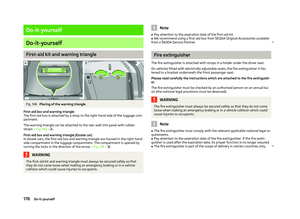 180
180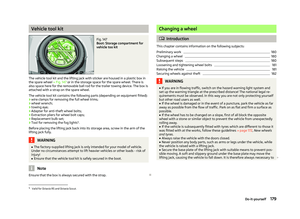 181
181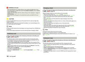 182
182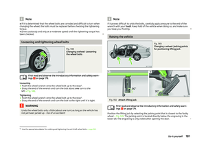 183
183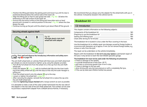 184
184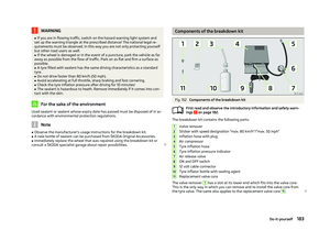 185
185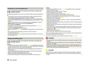 186
186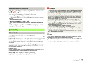 187
187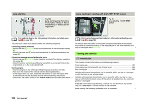 188
188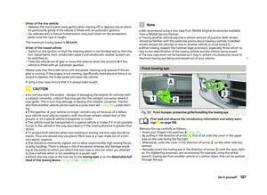 189
189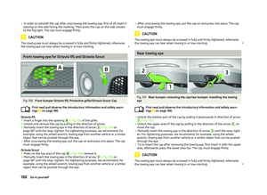 190
190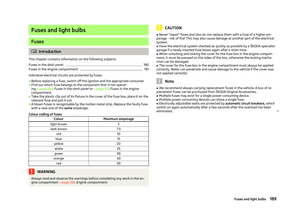 191
191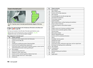 192
192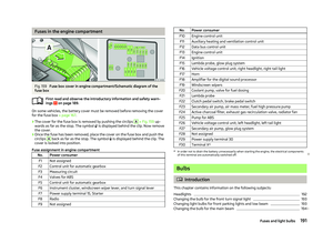 193
193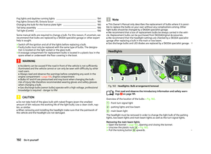 194
194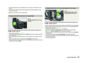 195
195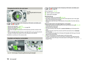 196
196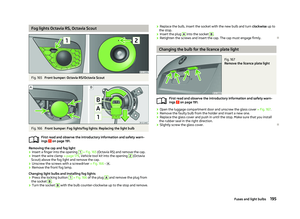 197
197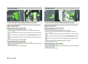 198
198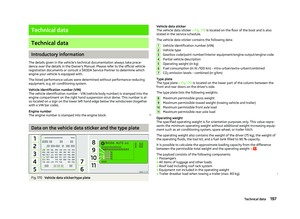 199
199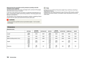 200
200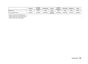 201
201 202
202 203
203 204
204 205
205 206
206 207
207 208
208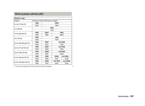 209
209 210
210 211
211 212
212 213
213 214
214 215
215 216
216 217
217