Page 185 of 218

WARNING
■ If you are in flowing traffic, switch on the hazard warning light system and
set up the warning triangle at the prescribed distance! The national legal re-
quirements must be observed. In this way you are not only protecting yourself
but other road users as well.
■ If the wheel is damaged or in the event of a puncture, park the vehicle as far
away as possible from the flow of traffic. Park on as flat and firm a surface as
possible. ■ A tyre filled with sealant has the same driving characteristics as a standard
tyre.
■ Do not drive faster than 80 km/h (50 mph).
■ Avoid accelerating at full throttle, sharp braking and fast cornering.
■ Check the tyre inflation pressure after driving for 10 minutes!
■ The sealant is hazardous to heath. Remove immediately if it comes into con-
tact with the skin. For the sake of the environment
Used sealant or sealant whose expiry date has passed must be disposed of in ac-
cordance with environmental protection regulations. Note
■ Observe the manufacturer's usage instructions for the breakdown kit.
■ A new bottle of sealant can be purchased from ŠKODA Original Accessories.
■ Immediately replace the wheel that was repaired using the breakdown kit or
consult a ŠKODA specialist garage about repair possibilities. Ð Components of the breakdown kit
Fig. 152
Components of the breakdown kit
First read and observe the introductory information and safety warn-
ings on page 182.
The breakdown kit contains the following parts:
Valve remover
Sticker with speed designation
“max. 80 km/h”/“max. 50 mph”
Inflation hose with plug
Air compressor
Tyre inflation hose
Tyre inflation pressure indicator
Air release valve
ON and OFF switch
12 volt cable connector
Tyre inflator bottle with sealing agent
Replacement valve core
The valve remover 1
has a slot at its lower end which fits into the valve core.
This is the only way in which you can remove and re-install the valve core from
the tyre valve. The same also applies to the replacement valve core 11
.
Ð
ä 1
2
3
4
5
6
7
8
9
10
11
183
Do-it-yourself
Page 186 of 218

Preparing to use the breakdown kit
First read and observe the introductory information and safety warn-
ings on page 182.
The following preparatory work must be carried out before using the breakdown
kit.
›
In the event of a puncture, park the vehicle as far away as possible from the
flow of traffic. Park on as flat and firm a surface as possible.
› Let all of the occupants get out.
While changing a tyre, the occupants of the
vehicle should not stand on the road (instead they should remain behind a crash
barrier).
› Switch off the engine and move the gearshift lever into
Neutral or move the
selector lever for the automatic gearbox into position P .
› Firmly apply the
handbrake.
› Check that you can carry out the repairs with the breakdown kit
» page 182.
› If a trailer is connected, remove it.
› Remove the breakdown kit
from the boot.
› Stick the sticker 2
»
Fig. 152
on page 183 on the dash panel in view of the driv-
er.
› Do not remove the foreign body, e.g. screw or nail, from the tyre.
› Unscrew the valve cap.
› Use the valve remover 1
to unscrew the valve core and place it on a clean sur-
face (rag, paper, etc.). ÐSealing and inflating tyres
First read and observe the introductory information and safety warn-
ings on page 182.
Sealing
›
Forcefully shake the tyre inflator bottle 10
» Fig. 152 on page 183 several times.
› Firmly screw the inflation hose 3
onto the tyre inflator bottle 10
in a clockwise
direction. The film on the cap is pierced automatically.
› Remove the plug from the inflation hose 3
and plug the open end fully onto
the tyre valve.
› Hold the bottle 10
with the bottom facing upwards and fill all of the sealing
agent from the tyre inflator bottle into the tyre.
› Remove the empty tyre inflator bottle from the valve.
› Screw the valve core back into the tyre valve using the valve remover 1
.
ä
ä
Inflating
› Screw the tyre inflation hose 5
» Fig. 152 on page 183 of the air compressor
firmly onto the tyre valve.
› Check that the air release valve 7
is closed.
› Start the engine and run it in idle.
› Plug the connector 9
into 12 Volt socket »
page 69.
› Switch on the air compressor with the ON and OFF switch 8
.
› Allow the air compressor to run until a pressure of 2.0 - 2.5 bar is achieved.
Maximum run time of 8 minutes » !
› Switch off the air compressor.
› If you cannot reach an air pressure of 2.0 – 2.5 bar, unscrew the tyre inflation
hose 5
from the tyre valve.
› Drive the vehicle 10 metres forwards or backwards to allow the sealing agent to
“distribute” in the tyre.
› Firmly screw the tyre inflation hose 5
back onto the tyre valve and repeat the
inflation process.
› If you cannot reach the required tyre inflation pressure here either, this means
the tyre has sustained too much damage. You cannot seal with tyre with the
breakdown kit » .
› Switch off the air compressor.
› Remove the tyre inflation hose 5
from the tyre valve.
Once a tyre inflation pressure of 2.0
– 2.5 bar is achieved, continue the journey at
a maximum speed of 80 km/h (50 mph).
Check the tyre inflation pressure after driving for 10 minutes » page 185. WARNING
■ During inflation, the tyre inflation hose and air compressor may get hot- risk
of injury!
■ Do not place the hot tyre inflation hose or hot air compressor on flammable
materials - risk of fire!
■ If you cannot inflate the tyre to at least 2.0 bar, this means the damage sus-
tained was too serious. The sealing agent cannot be used to seal the tyre. Do
not drive the vehicle. Get professional assistance! CAUTION
Switch off the air compressor after running 8 minutes at the latest - danger of
overheating! Allow the air compressor to cool a few minutes before switching it
on again. Ð
184 Do-it-yourself
Page 187 of 218

Check after driving for 10 minutes
First read and observe the introductory information and safety warn-
ings on page 182.
Check the tyre inflation pressure after driving for 10 minutes!
If the tyre inflation pressure is 1.3 bar or less:
›
Do not drive the vehicle!
You cannot properly seal with tyre with the break-
down kit.
› Get professional assistance.
If the tyre inflation pressure is 1.3 bar or more:
› Adjust the tyre inflation pressure to the correct value (see inside of fuel filler
cap).
› Continue driving carefully to the nearest ŠKODA specialist garage at a maxi-
mum speed of 80 km/h (50 mph). ÐJump-starting
ä
Introduction
This chapter contains information on the following subjects:
Jump-starting 186
Jump-starting in vehicles with the START-STOP system 186
The battery of another vehicle can be used to jump-start your vehicle if the en-
gine will not start because the battery is flat. Jump-start cables are required for
this purpose.
Both batteries must have a rated voltage of 12 V. The capacity (Ah) of the battery
supplying the power must not be significantly less than the capacity of the dis-
charged battery in your vehicle.
Jump-start cables
Only use jump-start cables which have an adequately large cross-section and in-
sulated terminal clamps. Observe the manufacturer's instructions.
Positive cable - colour coding in the majority of cases is red.
Negative cable - colour coding in the majority of cases is black.
ä WARNING
■ A discharged vehicle battery may already freeze at temperatures just below
0 °C. In case of frozen battery carry out no jump-starting - risk of explosion!
■ Pay attention to the warning instructions relating to working in the engine
compartment » page 158, Engine compartment .
■ The non-insulated parts of the terminal clamps must never make contact
with each other. In addition, the jump-start cable connected to the positive
terminal of the battery must not come into contact with electrically conduct-
ing parts of the vehicle - risk of short circuit! ■ Do not clamp the jump-start cable to the negative terminal of the dis-
charged battery. There is the risk of detonating gas seeping out the battery
being ignited by the strong spark which results from the engine being started.
■ Route the jump-start cables so that they cannot be caught by any rotating
parts in the engine compartment.
■ Do not bend over the battery - risk of caustic burns!
■ The vent screws of the battery cells must be tightened firmly.
■ Keep any sources of ignition (naked flame, smouldering cigarettes, etc.)
away from the battery - risk of an explosion! ■ Never jump-start vehicle batteries with an electrolyte level that is too low -
risk of explosion and caustic burns. Note
■ There must not be any contact between the two vehicles otherwise current
may flow as soon as the negative terminals are connected. ■ The discharged battery must be properly connected to the system of the vehi-
cle. ■ We recommend you buy jump-start cables from a car battery specialist. Ð
185
Do-it-yourself
Page 188 of 218

Jump-starting
Fig. 153
Jump-starting using the battery
from another vehicle: A - flat ve-
hicle battery, B - battery provid-
ing current
First read and observe the introductory information and safety warn-
ings on page 185.
The jump-start cables must be attached in the following sequence.
Connecting positive terminals
›
Attach one end 1
» Fig. 153
to the positive terminal of the discharged batteryA
.
› Attach the other end 2
to the positive terminal of the battery supplying the
power B
.
Connecting negative terminal and engine block
› Attach one end 3
»
Fig. 153
to the negative terminal of the battery supplying
the power B
.
› Attach the other end 4
to a solid metal part which is connected firmly to the
engine block, or to the engine block itself.
Starting engine
› Start the engine on the vehicle providing the power and allow it to idle.
› Now start the engine of the vehicle with the discharged battery.
› If the engine does not start, terminate the attempt to start the engine after
10 seconds and wait for about 30 seconds before repeating the process.
› Disconnect the cables in exactly the
reverse order to the one described above. Ð
ä Jump-starting in vehicles with the START-STOP system
Fig. 154
Jump-starting - START-STOP
system
First read and observe the introductory information and safety warn-
ings on page 185.
On vehicles with the START-STOP system, the jump-start cable of the charger
must never be connected directly to the negative pole of the vehicle battery, but
only to the engine earth » Fig. 154. Ð Towing the vehicle
ä
Introduction
This chapter contains information on the following subjects:
Front towing eye 187
Front towing eye for Octavia RS and Octavia Scout 188
Rear towing eye 188
Vehicles with manual transmission can be towed in with a tow bar or a tow rope
or with the front or rear wheels raised.
Vehicles with automatic transmission can be towed in with a tow bar or a tow
rope or with the front wheels raised. If the vehicle is raised at rear, the automatic
gearbox is damaged!
A tow bar is the safest way of towing a vehicle and also minimises any shocks.
Only use a tow rope if a suitable tow bar is not available.
When towing, the following guidelines must be observed. £
ä
186 Do-it-yourself
Page 189 of 218

Driver of the tow vehicle
›
Release the clutch particularly gently when starting off or depress the accelera-
tor particularly gently if the vehicle is fitted with an automatic gearbox.
› On vehicles with a manual transmission, only push down on the accelerator
pedal once the rope is taught.
The maximum towing speed is 50 km/h.
Driver of the towed vehicle
› Switch on the ignition so that the steering wheel is not blocked and so that the
turn signal lights, horn, windscreen wipers and windscreen washer system can
be switched on.
› Take the vehicle out of gear or move the selector lever into position
N if the
vehicle is fitted with an automatic gearbox.
Please note that the brake servo unit and power steering only operate if the en-
gine is running. If the engine is not running, significantly more physical force is re-
quired to depress the brake pedal and steer the vehicle.
If using a tow rope, ensure that it is always kept taught. CAUTION
■ Do not tow start the engine - danger of damaging the engine! On vehicles with
a catalytic converter, unburnt fuel may get into the catalytic converter where it
may ignite. This in turn may damage or destroy the catalytic converter. The bat-
tery from another vehicle can be used as a jump-start aid » page 185, Jump-start-
ing .
■ If the gearbox of your vehicle no longer contains any oil because of a defect,
your vehicle must only be towed in with the driven wheels raised clear of the
ground, or on a special vehicle transporter or trailer.
■ The vehicle must be transported on a special vehicle or trailer if it is not possible
to tow in the vehicle in the way described or if the towing distance is greater than
50 km. ■ To protect both vehicles when tow-starting or towing, the tow rope should be
elastic. Thus one should only use plastic fibre rope or a rope made out of a simi-
larly elastic material.
■ One should be constantly vigilant not to allow impermissibly high towing forces
or jerky loadings. There is always a risk of excessive stresses and damage result-
ing at the points to which you attach the tow rope or tow bar when you attempt
to tow a vehicle which is not standing on a paved road.
■ Attach the tow rope or the tow bar to the towing eyes or to the detachable ball
head of the towing device » page 187
or » page 188. Note
■ We recommend using a tow rope from
ŠKODA Original Accessories available
from a ŠKODA Service Partner. ■ Towing another vehicle requires a certain amount of practice. Both drivers
should be familiar with the particular points about towing a vehicle. Unskilled
drivers should not attempt to tow in another vehicle or to be towed in. ■ When towing, respect the national legal provisions, especially those which re-
late to the identification of the towing vehicle and the vehicle being towed. ■ The tow rope must not be twisted as it may in certain circumstances result in
the front towing eye being unscrewed out of your vehicle. Ð Front towing eye
Fig. 155
Front bumper: protective grille/installing the towing eye
First read and observe the introductory information and safety warn-
ings on page 186.
Remove the cap carefully as follows.
›
Insert your fingers into opening A
» Fig. 155 .
› By pulling in the direction of arrow 1
, first of all undo the cover in the upper
area on the side facing the fog light.
› Afterwards, undo the cover in the direction of arrow 2
on the other side too,
remove.
› Manually insert the towing eye in the direction of arrow 3
until the stop, tight-
en. For tightening purposes, we recommend, for example, using the wheel
wrench, towing eye from another vehicle or a similar object that can be pushed
through the eye. £
ä
187
Do-it-yourself
Page 190 of 218

›
In order to reinstall the cap after unscrewing the towing eye, first of all insert it
starting on the side facing the marking. Then press the cap on the side closest
to the fog light. The cap must engage firmly. CAUTION
The towing eye must always be screwed in fully and firmly tightened, otherwise
the towing eye can tear when towing in or tow-starting. ÐFront towing eye for Octavia RS and Octavia Scout
Fig. 156
Front bumper Octavia RS: Protective grille/Octavia Scout: Cap
First read and observe the introductory information and safety warn-
ings on page 186.
Octavia RS
›
Insert a finger into the opening A
» Fig. 156 of the grille.
› Unlock and remove the cap by pulling in the direction of arrow.
› Manually insert the towing eye in the direction of arrow 3
» Fig. 155
on
page 187 until the stop, tighten. For tightening purposes, we recommend, for
example, using the wheel wrench, towing eye from another vehicle or a similar
object that can be pushed through the eye.
› After unscrewing the towing eye, put the cap on and press into place. The cap
must engage firmly.
Octavia Scout
› Press on the top area of the cap B
» Fig. 156
, remove it.
› Manually insert the towing eye in the direction of arrow 3
»
Fig. 155
on
page 187 until the stop, tighten. For tightening purposes, we recommend, for
example, using the wheel wrench, towing eye from another vehicle or a similar
object that can be pushed through the eye.
ä ›
After unscrewing the towing eye, put the cap on and press into place. The cap
must engage firmly. CAUTION
The towing eye must always be screwed in fully and firmly tightened, otherwise
the towing eye can tear when towing in or tow-starting. Ð Rear towing eye
Fig. 157
Rear bumper: removing the cap/rear bumper: Installing the towing
eye
First read and observe the introductory information and safety warn-
ings on page 186.
›
Unlock the bottom part of the cap by pulling it downwards in direction of arrow 1
» Fig. 157.
› Unlock the upper area of the cap by pulling in the direction of the arrow 2
, re-
move the cap.
› Manually insert the towing eye in the direction of arrow 3
until the stop, tight-
en. For tightening purposes, we recommend, for example, using the wheel
wrench, towing eye from another vehicle or a similar object that can be pushed
through the eye.
› To re-insert the cap after removing the towing eye, first insert it with the upper
area, afterwards press the lower area too. The cap must engage firmly. CAUTION
The towing eye must always be screwed in fully and firmly tightened, otherwise
the towing eye can tear when towing in or tow-starting. Ð ä
188 Do-it-yourself
Page 191 of 218

Fuses and light bulbs
Fuses
ä
Introduction
This chapter contains information on the following subjects:
Fuses in the dash panel 190
Fuses in the engine compartment 191
Individual electrical circuits are protected by fuses.
› Before replacing a fuse, switch off the ignition and the appropriate consumer
› Find out which fuse belongs to the component that is not operat-
ing » page 190, Fuses in the dash panel or » page 191, Fuses in the engine
compartment .
› Take the plastic clip out of its fixture in the cover of the fuse box, place it on the
relevant fuse and pull it out.
› A blown fuses is recognisable by the molten metal strip. Replace the faulty fuse
with a new one of the
same amperage.
Colour coding of fuses Colour Maximum amperage
light brown 5
dark brown 7.5
red 10
blue 15
yellow 20
white 25
green 30
orange 40
red 50WARNING
Always read and observe the warnings before completing any work in the en-
gine compartment » page 158, Engine compartment . CAUTION
■ Never “repair” fuses and also do not replace them with a fuse of a higher am-
perage - risk of fire! This may also cause damage at another part of the electrical
system.
■ Have the electrical system checked as quickly as possible by a ŠKODA specialist
garage if a newly inserted fuse blows again after a short time.
■ When unlocking and locking the cover for the fuse box in the engine compart-
ment, it must be pressed on the sides of the box, otherwise the locking mecha-
nism can be damaged. ■ The cover for the fuse box in the engine compartment must always be applied
correctly. Water can penetrate and cause damage to the vehicle if the cover was
not applied correctly! Note
■ We recommend always carrying replacement fuses in the vehicle. A box of re-
placement fuses can be purchased from
ŠKODA Original Accessories.
■ Multiple fuses may exist for a single power consuming device.
■ Multiple power consuming devices can share a single fuse.
■ Electrically adjustable seats are protected by automatic circuit breakers, which
switch on again automatically after a few seconds after the overload has been
eliminated. Ð
189
Fuses and light bulbs
Page 192 of 218

Fuses in the dash panel
Fig. 158
Fuse box cover in the dash panel/schematic diagram of the fuse
box
First read and observe the introductory information and safety warn-
ings on page 189.
The fuses are located on the left side of the dash panel behind a cover.
›
Remove the cover for the fuse box using a screwdriver
» Fig. 158.
› Replace the cover once the fuse has been changed.
Fuse assignment in the dash panel No. Power consumer
1 Diagnostic socket, engine control unit, fuel pump
2 Control unit for ABS, ESC
3 Airbag
4 Heating, Air conditioning system, Reversing lights 5 Control unit for headlamp beam adjustment
6 Instrument cluster, control unit for automatic gearbox, control unit for
electromechanical power steering, parking aid
7-11 Not assigned 12 Central locking control unit
13 Diagnostic socket, Light switch
14 Control unit for automatic gearbox, Selector lever lock 15 Vehicle voltage control unit - interior lights
16 Climatronic ä
No. Power consumer
17 Not assigned
18 Rear window wiper 19 Control unit for trailer detection
20 Not assigned 21 Cornering lights for the left and right side
22 Air blower for Climatronic
23 Front power window
24 Cigarette lighter 25 Rear window heater, auxiliary heating and ventilation
26 Power socket in the boot 27 Fuel pump, Injection valves (diesel engine)
28 Radio 29 Engine control unit, Crankcase ventilation heater
30 Control unit for automatic gearbox, Haldex 31 Vacuum pump
32 Rear power window
33 Electric sliding/tilting roof
34 Control unit for convenience functions 35 Alarm
36 Headlight cleaning system 37 Heated front seats
38 Heated rear seats 39 Instrument cluster, windscreen wiper lever, and turn signal lever
40 Air blower for heating and air conditioning
41-42 Not assigned
43-45 Towing device 46 Seat heaters47 Auxiliary heating and ventilation
48 Phone 49 Light switch Ð
190 Do-it-yourself
 1
1 2
2 3
3 4
4 5
5 6
6 7
7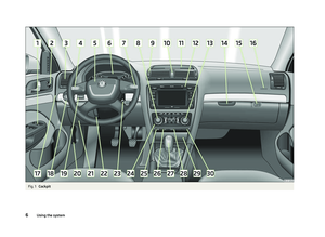 8
8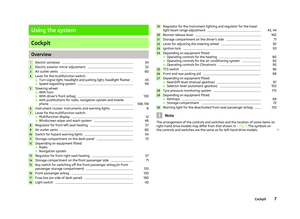 9
9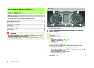 10
10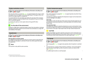 11
11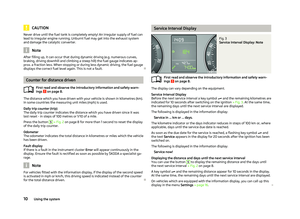 12
12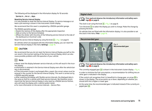 13
13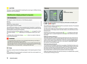 14
14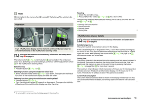 15
15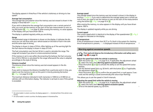 16
16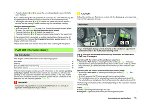 17
17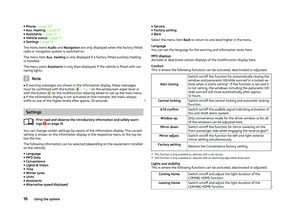 18
18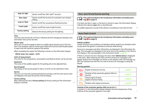 19
19 20
20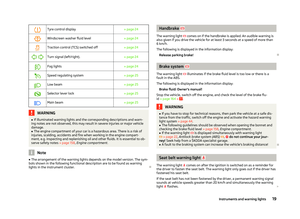 21
21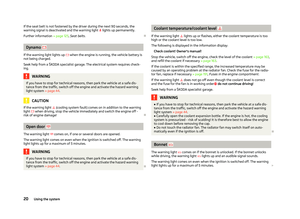 22
22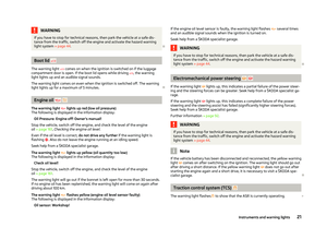 23
23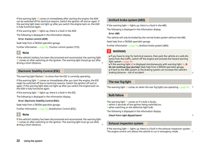 24
24 25
25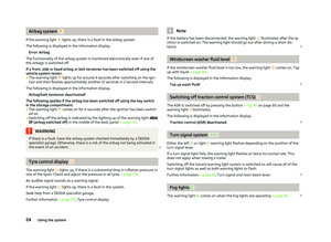 26
26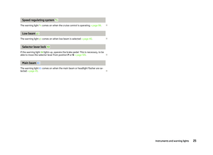 27
27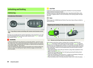 28
28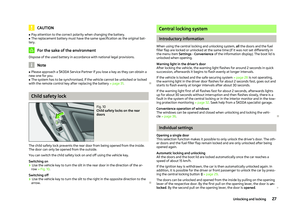 29
29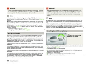 30
30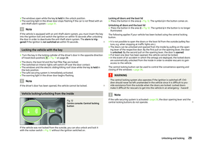 31
31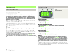 32
32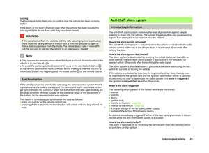 33
33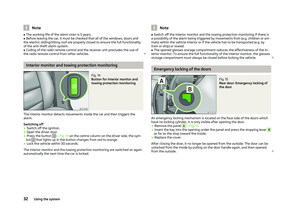 34
34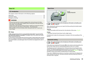 35
35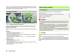 36
36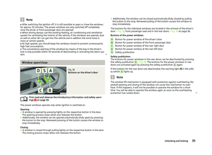 37
37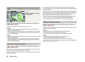 38
38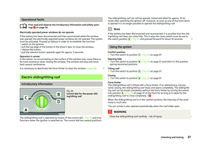 39
39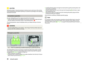 40
40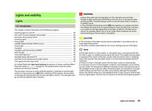 41
41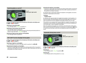 42
42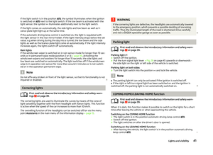 43
43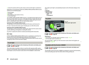 44
44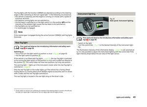 45
45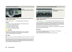 46
46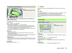 47
47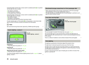 48
48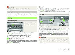 49
49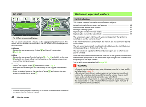 50
50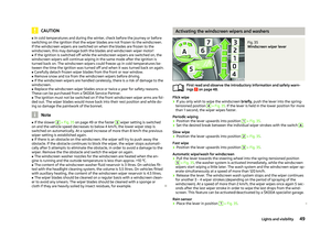 51
51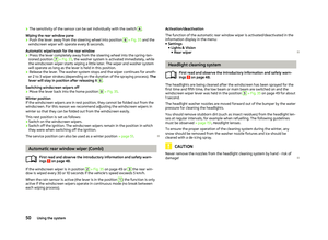 52
52 53
53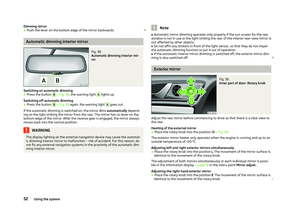 54
54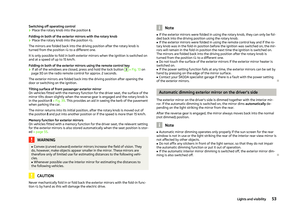 55
55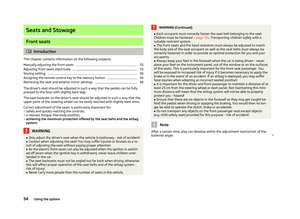 56
56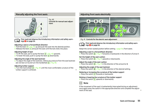 57
57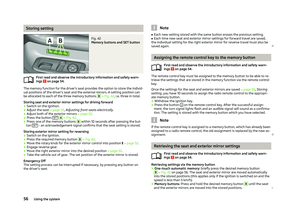 58
58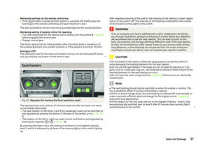 59
59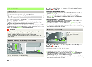 60
60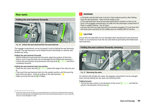 61
61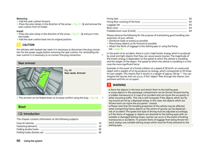 62
62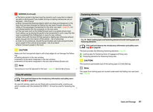 63
63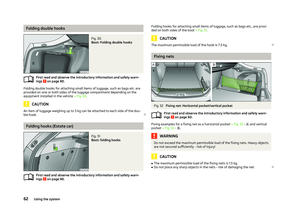 64
64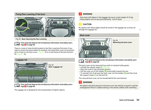 65
65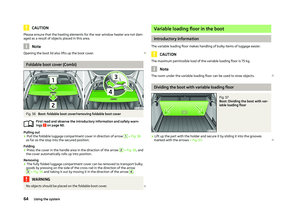 66
66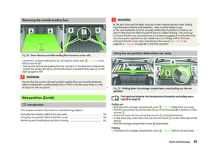 67
67 68
68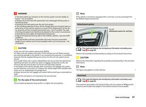 69
69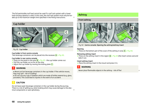 70
70 71
71 72
72 73
73 74
74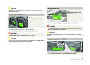 75
75 76
76 77
77 78
78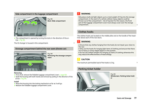 79
79 80
80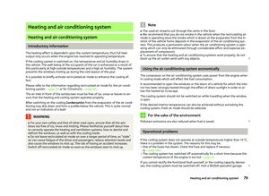 81
81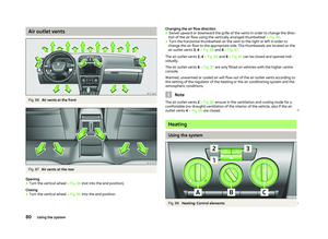 82
82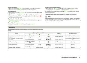 83
83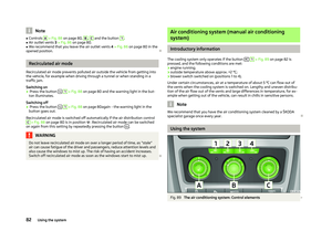 84
84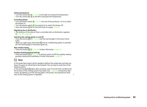 85
85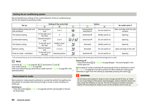 86
86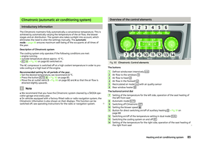 87
87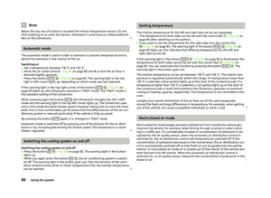 88
88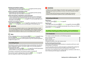 89
89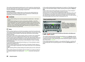 90
90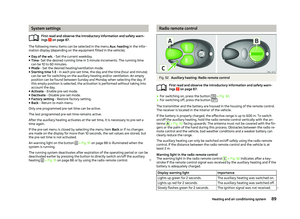 91
91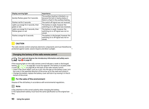 92
92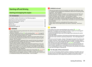 93
93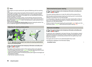 94
94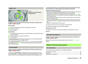 95
95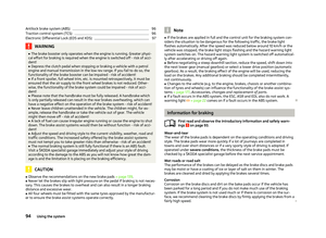 96
96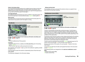 97
97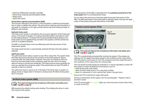 98
98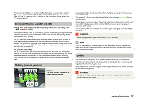 99
99 100
100 101
101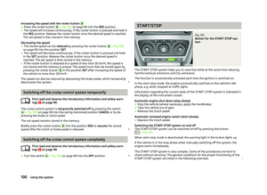 102
102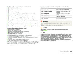 103
103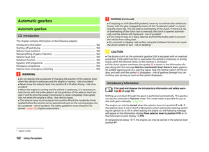 104
104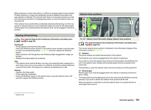 105
105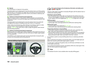 106
106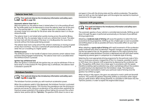 107
107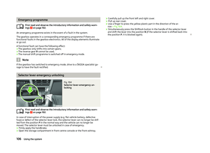 108
108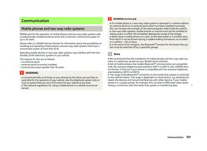 109
109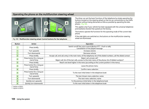 110
110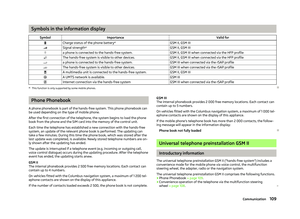 111
111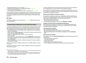 112
112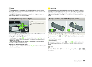 113
113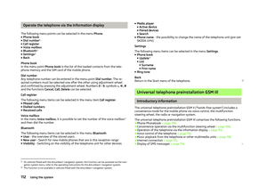 114
114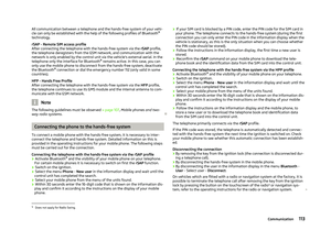 115
115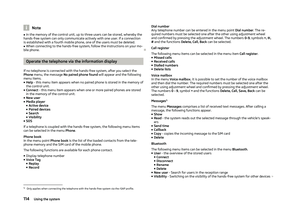 116
116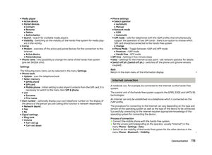 117
117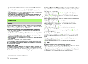 118
118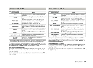 119
119 120
120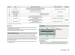 121
121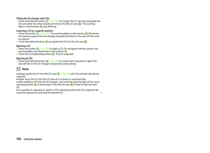 122
122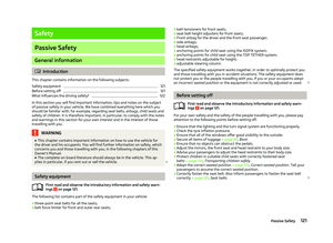 123
123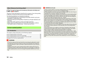 124
124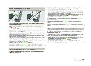 125
125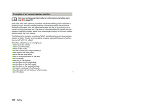 126
126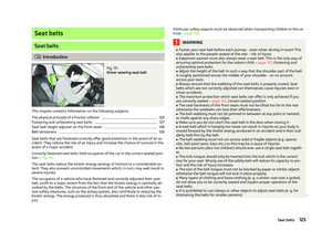 127
127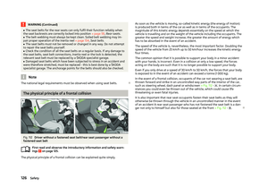 128
128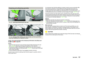 129
129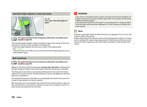 130
130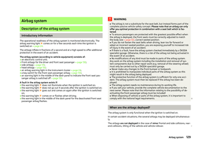 131
131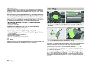 132
132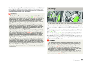 133
133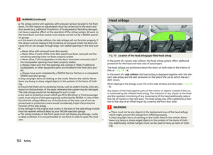 134
134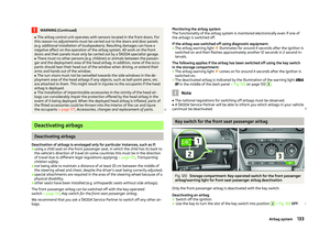 135
135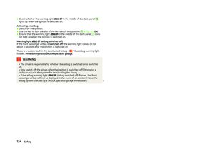 136
136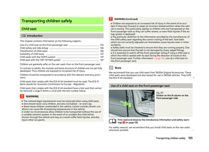 137
137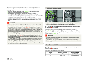 138
138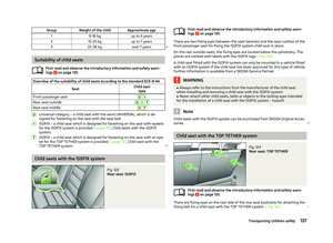 139
139 140
140 141
141 142
142 143
143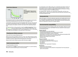 144
144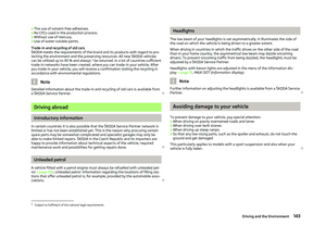 145
145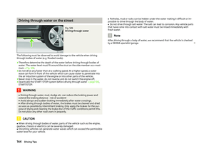 146
146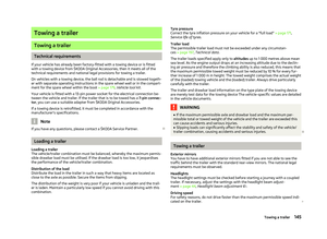 147
147 148
148 149
149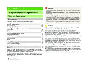 150
150 151
151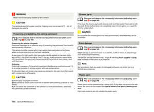 152
152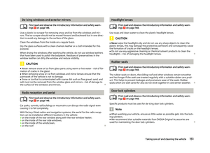 153
153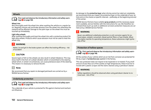 154
154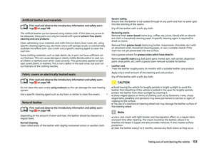 155
155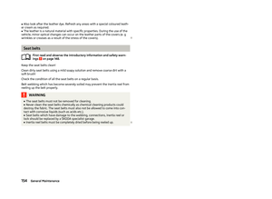 156
156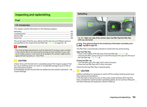 157
157 158
158 159
159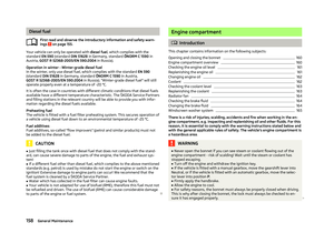 160
160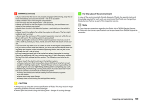 161
161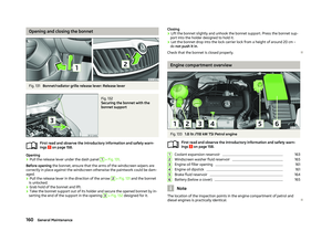 162
162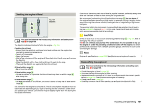 163
163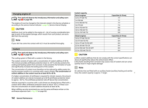 164
164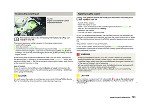 165
165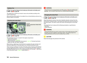 166
166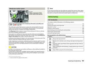 167
167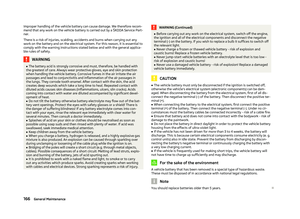 168
168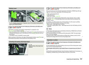 169
169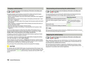 170
170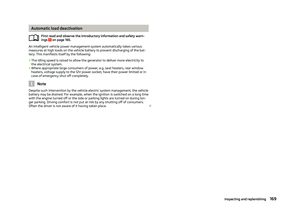 171
171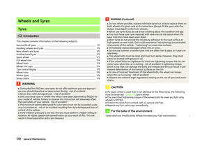 172
172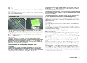 173
173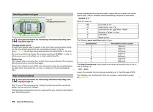 174
174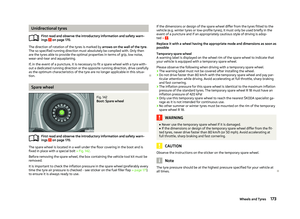 175
175 176
176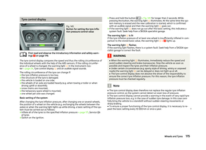 177
177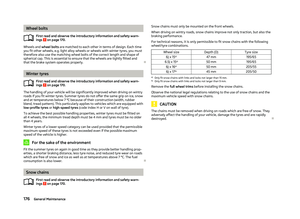 178
178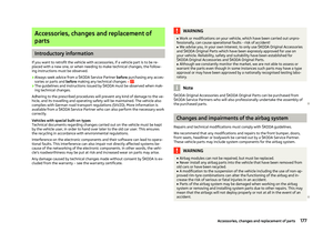 179
179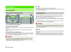 180
180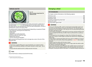 181
181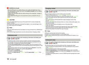 182
182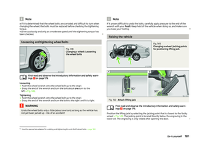 183
183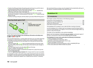 184
184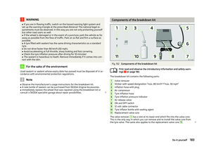 185
185 186
186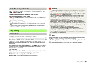 187
187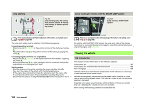 188
188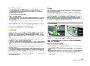 189
189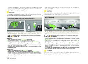 190
190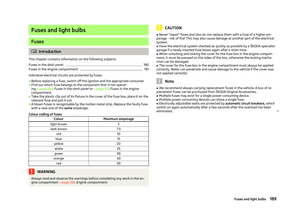 191
191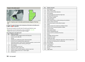 192
192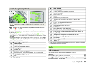 193
193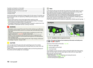 194
194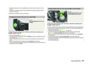 195
195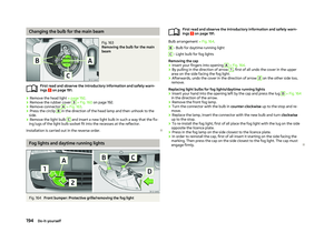 196
196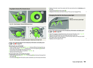 197
197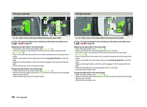 198
198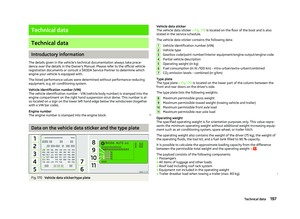 199
199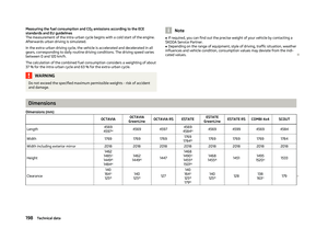 200
200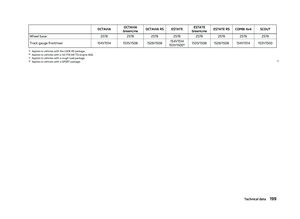 201
201 202
202 203
203 204
204 205
205 206
206 207
207 208
208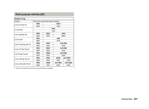 209
209 210
210 211
211 212
212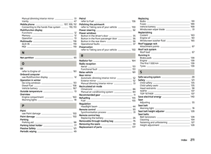 213
213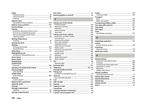 214
214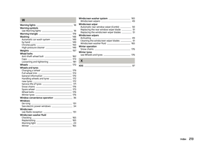 215
215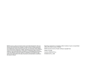 216
216 217
217