Page 57 of 218

Manually adjusting the front seats
Fig. 40
Controls for manual seat adjust-
ment
First read and observe the introductory information and safety warn-
ings on page 54.
Adjusting a seat in a forward/back direction
›
Pull the lever 1
» Fig. 40 up and push the seat into the desired position.
› Release the lever 1
and push the seat until the lock clicks into place.
Adjusting height of seat
› To lift the seat, pull or pump the lever 2
» Fig. 40 upwards.
› To lower the seat, push or pump the lever 2
downwards.
Adjusting the angle of the seat backrest
› To adjust the angle of the backrest, relieve any pressure from the seat backrest
(do not lean on it) and turn the handwheel 3
» Fig. 40.
Adjusting lumbar support
› Turn the hand wheel 4
» Fig. 40
until the most comfortable curvature of the
lumbar support is achieved. Ð
ä Adjusting front seats electrically
Fig. 41
Controls for the electric seat adjustment
First read and observe the introductory information and safety warn-
ings on page 54.
Adopt the correct seated position before setting
» page 54, Front seats.
Adjusting a seat in a forward/back direction
› Press the switch A
» Fig. 41
forwards or backwards in the direction of arrow 1.
Set the height of the seat cushion
› Press the switch A
»
Fig. 41
upwards or downwards.
Adjust the angle of the seat cushion
› Press the switch A
»
Fig. 41
in the direction of the arrow 2 or 3.
Adjusting the angle of the seat backrest
› Press the switch B
»
Fig. 41
in the direction of the desired setting.
Reducing or increasing the curvature of the lumbar support
› Press the switch C
forwards or backwards.
Raising or lowering the curvature of the lumbar support
› Press the switch C
upwards or downwards.
Note
If the movement of the seat is inadvertently interrupted during an adjustment,
once again press the switch in the appropriate direction and complete the adjust-
ment of the seat. Ð
ä
55
Seats and Stowage
Page 58 of 218

Storing setting
Fig. 42
Memory buttons and SET button
First read and observe the introductory information and safety warn-
ings on page 54.
The memory function for the driver's seat provides the option to store the individ-
ual positions of the driver's seat and the external mirrors. A setting position can
be allocated to each of the three memory buttons B
» Fig. 42, i.e. three in total.
Storing seat and exterior mirror settings for driving forward
› Switch on the ignition.
› Adjust the seat
» page 55, Adjusting front seats electrically .
› Adjust both of the exterior mirrors
» page 52.
› Press the button
SET A
» Fig. 42.
› Press one of the memory buttons B
within 10 seconds after pressing the but-
ton SET - an acknowledgement signal confirms that the seat setting is stored.
Storing exterior mirror setting for reversing › Switch on the ignition.
› Press the required memory button B
» Fig. 42.
› Move the rotary knob for the exterior mirror control into position
» page 52.
› Engage reverse gear.
› Move the right exterior mirror into the desired position
» page 52.
› Take the vehicle out of gear. The set position of the exterior mirror is stored.
Emergency Off
The setting process can be interrupted if necessary, by pressing any button on
the driver's seat.
ä Note
■ Each new setting stored with the same button erases the previous setting.
■ Each time new seat and exterior mirror settings for forward travel are saved,
the individual setting for the right exterior mirror for reverse travel must also be
saved again. Ð Assigning the remote control key to the memory button
First read and observe the introductory information and safety warn-
ings on page 54.
The remote control key must be assigned to the memory button to be able to re-
trieve the settings that are stored in the memory function via the remote control
key.
Once the settings for the seat and exterior mirrors are saved » page 56, Storing
setting, you have 10
seconds to assign the radio remote control to the appropri-
ate memory button.
› Withdraw the ignition key.
› Press the button
on the remote control key. After the successful assign-
ment, the turn signal lights flash and an audible signal will sound as a confirma-
tion. The setting is stored with the memory button which you have selected. Note
If the remote control key is assigned to a memory button, which has already been
assigned to a radio remote control, the old assignment is replaced by the new as-
signment. Ð Retrieving the seat and exterior mirror settings
First read and observe the introductory information and safety warn-
ings on page 54.
Retrieving settings via the memory button
›
One-touch automatic memory:
briefly press the desired memory button B
» Fig. 42 on page 56. The seat and exterior mirror are moved automatically
into the stored positions (this applies only if the ignition is switched on and the
speed is less than 5 km/h).
› Memory buttons:
Press and hold the desired memory button B
until the seat
and the exterior mirrors are moved into the stored positions. £
ä
ä
56 Using the system
Page 59 of 218

Retrieving settings via the remote control key
›
If the driver's door is closed and the ignition is switched off, briefly press the
button on the remote control key and open the driver's door.
The seat and exterior mirrors now move automatically into the stored positions.
Retrieving setting of exterior mirror for reversing
› Turn the rotary knob for the exterior mirror setting into the position
» page 52
before engaging the reverse gear.
› Engage reverse gear.
The mirror returns into its initial position, after the rotary knob is moved out of
the position and put into another position or if the speed is more than 15 km/h.
Emergency Off
The setting process for the seats and exterior mirrors can be interrupted if neces-
sary, by pressing any button on the driver's seat. ÐSeat heaters
Fig. 43
Regulator for heating the front seats/rear seats
The seat backrests and surfaces of the front seats and the two outer rear seats
can be heated electrically. › The seat heaters on the driver's and front passenger's seat can be switched on
and regulated by pressing the button in the area of the symbol or
»
Fig. 43 -
.
› The heaters on the left or right rear seats can be switched on and regulated by
pressing the regulator or
» Fig. 43 -
.
By pressing the button once, the heating is switched to the highest intensity -
level 3, which is indicated by all three of the warning lights in the switch lighting
up. With repeated pressing of the switch, the intensity of the heating is down-regula-
ted up to the switch-off. The intensity of the heating is indicated by the number
of illuminated warning lights in the switch. WARNING
If, as an occupant, you have a subdued pain and/or temperature sensitivity,
e.g. through medication, paralysis or because of chronic illness (e.g. diabetes),
we recommend not to use the seat heating. This can lead to burns on the
back, the posterior and the legs which are difficult to heal. If the seat heating
is used, we recommend to make regular breaks in your journey when driving
long distances, so that the body can recuperate from the stress of the jour-
ney. Please consult your doctor, who can evaluate your specific condition. CAUTION
■ Do not kneel on the seats or otherwise apply pressure at specific points to
avoid damaging the heating elements for the seat heaters.
■ Do not use the seat heaters if the seats are not occupied by persons or if ob-
jects, such as a child seat, bag, etc., are fastened or stored on them. A fault of the
heating elements in the seat heating can occur.
■ Do not clean the seats using moisture » page 153, Fabric covers on electrically
heated seats. Note
■ The seat heating should only be switched on when the engine is running. This
has a significant effect of saving on the battery capacity. ■ If the on-board voltage drops, the seat heating is switched off automatically, in
order to provide sufficient electrical energy for the engine control » page 169,
Automatic load deactivation .
■ If the heaters for the rear seats are set to the highest intensity - level 3, they
are automatically switched over to level
2 after 10 minutes (two warning lights
are illuminated on the switch). Ð
57
Seats and Stowage
Page 60 of 218

Head restraints
ä
Introduction
This chapter contains information on the following subjects:
Adjusting, removing and installing a head restraint 58
Middle rear head restraint 58
Best protection is achieved if the top edge of the head restraint is at the same
level as the upper part of your head.
The position of the front and rear outer head restraints is adjustable in height.
The middle rear head restraint is adjustable in two positions.
The head restraints must be adjusted to match the size of the seat occupant. Cor-
rectly adjusted head restraints together with the seat belts offer effective protec-
tion for the occupants » page 122, Correct seated position .WARNING
■ The head restraints must be correctly adjusted in order to offer effective
protection for the occupants in the event of an accident. ■ Never drive with the head restraints removed - risk of injury.
■ If the rear seats are occupied, the rear head restraint must not be in the
lower position. ÐAdjusting, removing and installing a head restraint
Fig. 44
Head restraint: adjusting/removing First read and observe the introductory information and safety warn-
ings on page 58.
Adjusting the height of a head restraint
› Grasp the side of the head restraint with both hands and push it upwards as
required » Fig. 44 - .
› To move the head restraint downwards, press and hold the safety but-
ton » Fig. 44 - with one hand and press the head restraint downwards with
the other hand.
Removing and installing a head restraint
› Pull the head restraint up out of the seat backrest as far as the stop (for the
rear head restraints fold the seat backrest forward).
› Press the locking button in direction of the arrow
» Fig. 44 - and pull the
head restraint out.
› To re-insert the head restraint, push it far enough down into the seat backrest
until the locking button clicks into place. Ð Middle rear head restraint
Fig. 45
Rear seats: middle head re-
straint
First read and observe the introductory information and safety warn-
ings on page 58.
Applies to vehicles using the TOP TETHER system.
Removing and installing
› Pull the head restraint out of the seat backrest as far as the stop.
› Press the locking button in the direction of arrow 1
» Fig. 45
, simultaneously
press the locking button into the opening 2
using a flat screwdriver with a
width of maximum 5 mm and pull out the head restraint.
› To re-insert the head restraint, push it far enough down into the seat backrest
until the locking button clicks into place. Ð
ä
ä
58 Using the system
Page 61 of 218

Rear seats
Folding the seat backrest forwards
Fig. 46
Unlock the seat backrest/lock the seat backrest
The luggage compartment can be increased in size by folding the seat backrests
forward. The seat backrests can be folded forward individually on vehicles with
divided rear seats.
Folding the seat backrest forwards
› Before folding the seat backrests forwards, adapt the position of the front
seats in such a way that they are not damaged by the folded seat backrests 1)
.
› Unlock the seat backrest by pressing the securing knob A
» Fig. 46
and fold it
completely forwards.
Folding the seat backrest back into position
› Place the rear outer seat belt C
» Fig. 46 behind the edge of the side trim pan-
el.
› Then push the seat backrest back into the upright position until the securing
knob clicks into place - check by pulling on the seat backrest » .
› Make sure that the red pin B
is hidden. WARNING
■ The belts and the belt locks must be in their original position after folding
back the seat backrests - they must be ready to use.
■ The seat backrests must be securely interlocked in position so that no ob-
jects in the luggage compartment can slide into the passenger compartment if
there is sudden braking - risk of injury! ■ Ensure that the rear seat backrests are properly engaged. It is only then that
the three-point seat belt for the middle seat can reliably fulfil its function. CAUTION
Ensure that the seat belts are not damaged when operating the seat backrests.
Under no circumstances must the rear seat belts be jammed by the folded back
seat backrests. Ð Folding the seat cushions forwards, removing
Fig. 47
Removing the seats
On vehicles with divided rear seats, the luggage compartment can be enlarged
even more by folding the rear seats and removing them.
Folding forward
› Pull up the seat cushion in the direction of the arrow 1
» Fig. 47 and fold for-
wards in the direction of the arrow 2
.
£1)
If the front seats are too far back, we recommend that you have the rear head restraints removed
before the seat backrests are folded forward. Store the removed head restraints in such a way that
they are not be damaged or soiled.
59
Seats and Stowage
Page 62 of 218

Removing
›
Fold the seat cushion forward.
› Press the wire clamps in the direction of the arrow
» Fig. 47 - and remove the
seat cushion from its holder.
Install
› Press the wire clamp in the direction of the arrow
» Fig. 47 - and put it into
the holder.
› Fold the seat cushion back into its original position. CAUTION
For vehicles with heated rear seats it is necessary to disconnect the plug connec-
tion for the power supply before removing the seat cushion. For reinstalling the
seat cushion it is necessary to re-connect the plug connection. ÐRear armrest
Fig. 48
Rear seats: Armrest
› The armrest can be folded down to increase comfort using the loop
» Fig. 48.Ð Boot
ä
Introduction
This chapter contains information on the following subjects:
Class
N1 vehicles 61
Fastening elements 61
Folding double hooks 62
Folding hooks (Estate car) 62Fixing nets 62
Fixing floor covering of the boot 63
Luggage net 63
Boot cover 63
Foldable boot cover (Combi) 64
Please observe the following for the purpose of maintaining good handling char-
acteristics of your vehicle:
› Distribute loads as evenly as possible.
› Place heavy objects as far forward as possible.
› Attach the items of luggage to the lashing eyes or using the fixing
net »
page 61 .
In the event of an accident, there is such a high kinetic energy which is produced
by small and light objects that they can cause severe injuries. The magnitude of
the kinetic energy is dependent on the speed at which the vehicle is travelling
and the weight of the object. The speed at which the vehicle is travelling is in this
case the more significant factor.
Example: In the event of a frontal collision at a speed of 50 km/h, an unsecured
object with a weight of 4.5 kg produces an energy, which corresponds to 20 times
its own weight. This means that it results in a weight of approx. 90 kg “ ”. You can
imagine the injuries that can occur, if this “object” flies through the interior com-
partment and hits an occupant. WARNING
■ Store the objects in the boot and attach them to the lashing eyes.
■ Loose objects in the passenger compartment can be thrown forward during
a sudden manoeuvre or in case of an accident and can injure the occupants or
other oncoming traffic. This risk is still increased, if the objects which are fly-
ing around are hit by a deployed airbag. In this case, the objects which are
thrown back can injure the occupants - hazard. ■ Please note that the handling properties of the vehicle may be affected
when transporting heavy objects as the centre of gravity can be displaced -
risk of accident! The speed and style of driving must be adjusted accordingly. ■ If the items of luggage or objects are attached to the lashing eyes with un-
suitable or damaged lashing straps, injuries can occur in the event of braking
manoeuvres or accidents. To prevent items of luggage from being thrown for-
ward, always use suitable lashing straps which must be firmly attached to the
lashing eyes. £
60 Using the system
Page 63 of 218

■ The items carried in the boot must be stored in such a way that no objects
are able to slip forward if any sudden driving or braking manoeuvres are un-
dertaken - risk of injur")
WARNING (Continued)
■ The items carried in the boot must be stored in such a way that no objects
are able to slip forward if any sudden driving or braking manoeuvres are un-
dertaken - risk of injury! ■ When transporting fastened objects which are sharp and dangerous in the
boot that has been enlarged by folding the rear seats forward, ensure the
safety of the passengers transported on the other rear seats » page 123, Cor-
rect seated position for the occupants on the rear seats .
■ If the rear seat next to the folded forward seat is occupied, ensure maxi-
mum safety, e.g. by placing the goods to be transported in such a way that the
seat is prevented from folding back in case of a rear collision.
■ Never drive with the boot lid fully opened or slightly ajar otherwise exhaust
gases may get into the interior of the vehicle - risk of poisoning!
■ Under no circumstances, should the permissible axle loads and permissible
gross weight of the vehicle be exceeded - risk of accident!
■ Never transport people in the boot! CAUTION
Make sure that transported objects with sharp edges do not damage the follow-
ing:
■ heating elements in the rear window;
■ elements of the aerial integrated in the rear window;
■ elements of the aerial integrated in the rear side windows (Estate car). Note
Tyre pressure must be adjusted to the load » page 171, Service life of tyres.ÐClass N1 vehicles
First read and observe the introductory information and safety warn-
ings on page 60.
On class N1 vehicles, which are not fitted with a protective grille, a lashing set
which complies with the standard EN
12195 (1 - 4) must be used for fastening the
load. Ð
ä Fastening elements
Fig. 49
Boot: Lashing eyes and fastening elements/Combi lashing eyes and
fastening elements
First read and observe the introductory information and safety warn-
ings on page 60.
The boot provides the following fastening elements
»
Fig. 49.
Lashing eyes for fastening items of luggage and fixing nets.
Fastening elements for fastening fixing nets. CAUTION
The maximum permissible load of the lashing eyes is 3.5 kN (350 kg). Note
The upper front lashing eyes are located underneath the folding rear seat back-
rest » Fig. 49. Ð
ä A
B
61
Seats and Stowage
Page 64 of 218

Folding double hooks
Fig. 50
Boot: Folding double hooks
First read and observe the introductory information and safety warn-
ings on page 60.
Folding double hooks for attaching small items of luggage, such as bags etc. are
provided on one or both sides of the luggage compartment depending on the
equipment installed in the vehicle » Fig. 50.CAUTION
An item of luggage weighing up to 5 kg can be attached to each side of the dou-
ble hook. ÐFolding hooks (Estate car)
Fig. 51
Boot: folding hooks
First read and observe the introductory information and safety warn-
ings on page 60.ä
ä Folding hooks for attaching small items of luggage, such as bags etc., are provi-
ded on both sides of the boot » Fig. 51. CAUTION
The maximum permissible load of the hook is 7.5 kg. Ð Fixing nets
Fig. 52
Fixing net: Horizontal pocket/vertical pocket
First read and observe the introductory information and safety warn-
ings on page 60.
Fixing examples for a fixing net as a horizontal pocket
» Fig. 52 - and vertical
pocket » Fig. 52 - . WARNING
Do not exceed the maximum permissible load of the fixing nets. Heavy objects
are not secured sufficiently - risk of injury! CAUTION
■ The maximum permissible load of the fixing nets is 1.5
kg.
■ Do not place any sharp objects in the nets - risk of damaging the net. Ð
ä
62 Using the system
 1
1 2
2 3
3 4
4 5
5 6
6 7
7 8
8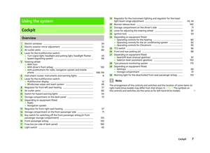 9
9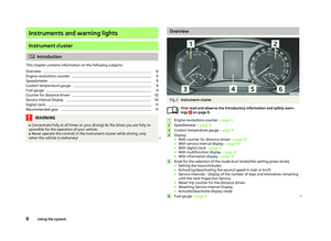 10
10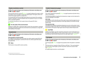 11
11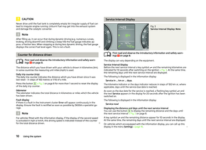 12
12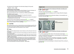 13
13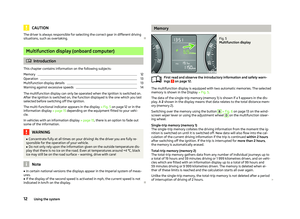 14
14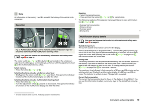 15
15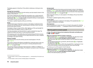 16
16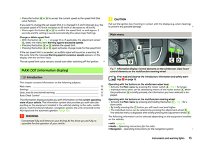 17
17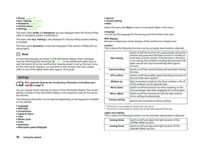 18
18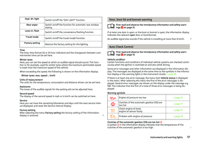 19
19 20
20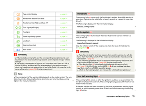 21
21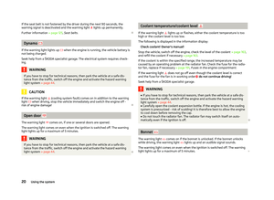 22
22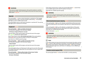 23
23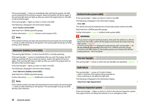 24
24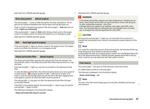 25
25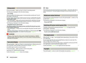 26
26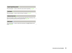 27
27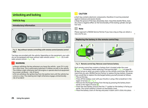 28
28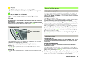 29
29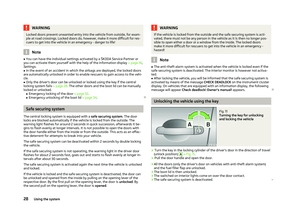 30
30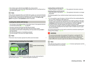 31
31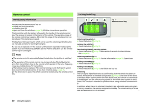 32
32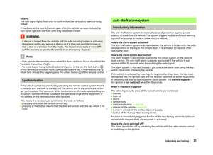 33
33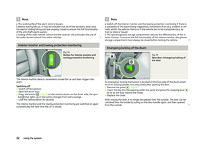 34
34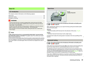 35
35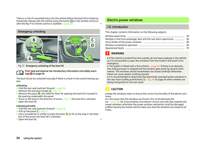 36
36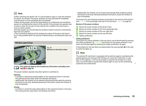 37
37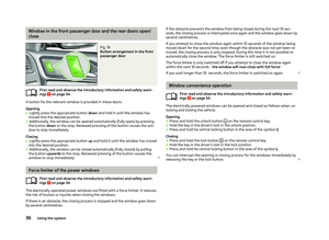 38
38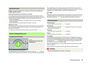 39
39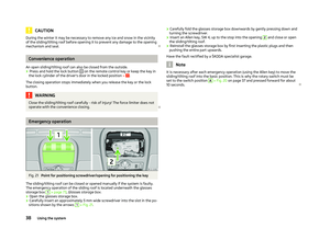 40
40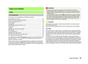 41
41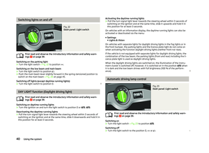 42
42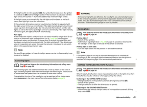 43
43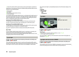 44
44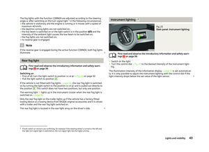 45
45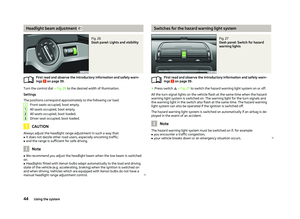 46
46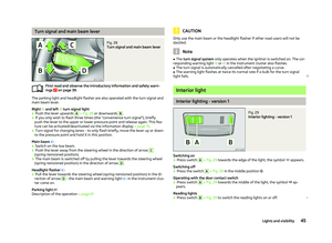 47
47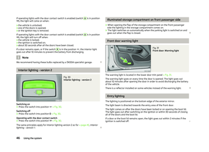 48
48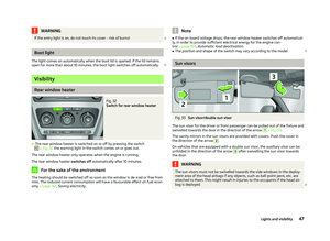 49
49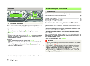 50
50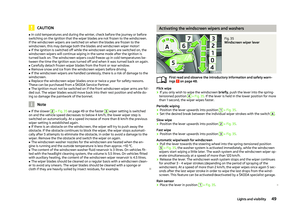 51
51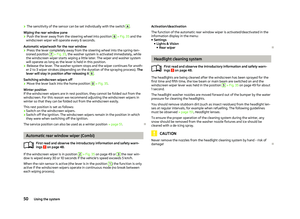 52
52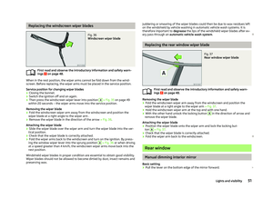 53
53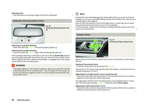 54
54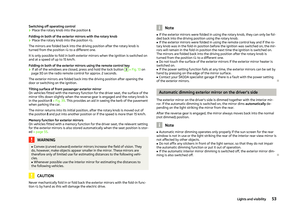 55
55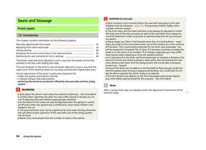 56
56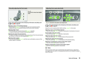 57
57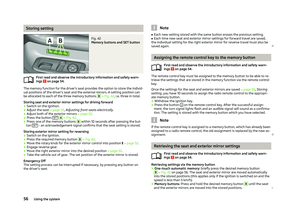 58
58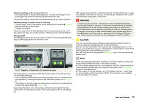 59
59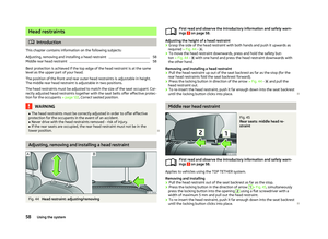 60
60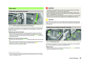 61
61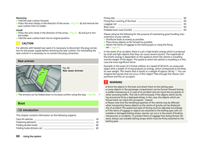 62
62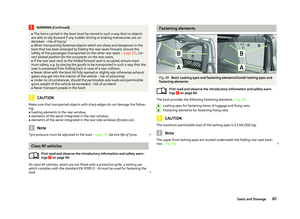 63
63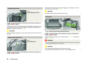 64
64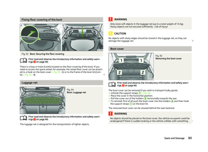 65
65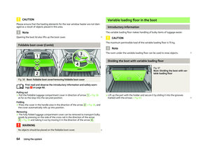 66
66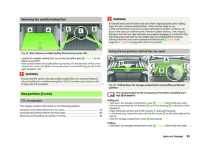 67
67 68
68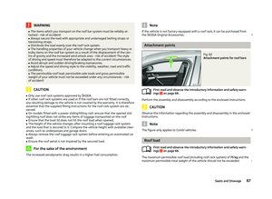 69
69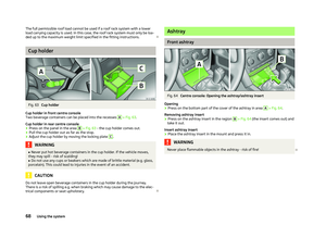 70
70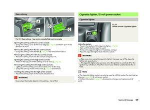 71
71 72
72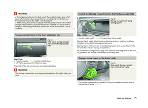 73
73 74
74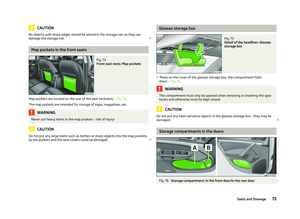 75
75 76
76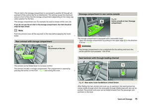 77
77 78
78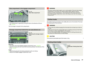 79
79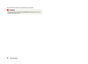 80
80 81
81 82
82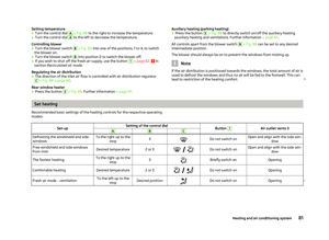 83
83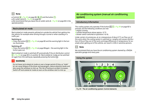 84
84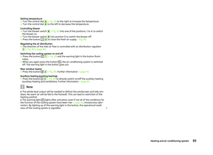 85
85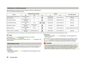 86
86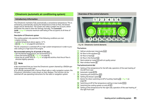 87
87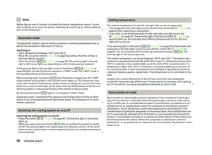 88
88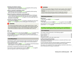 89
89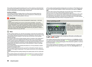 90
90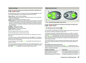 91
91 92
92 93
93 94
94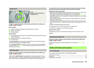 95
95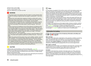 96
96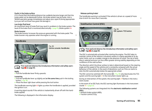 97
97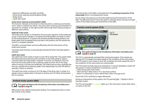 98
98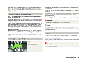 99
99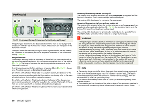 100
100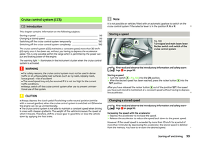 101
101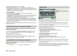 102
102 103
103 104
104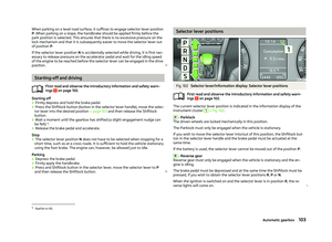 105
105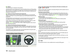 106
106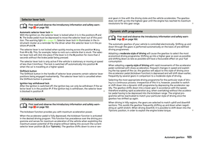 107
107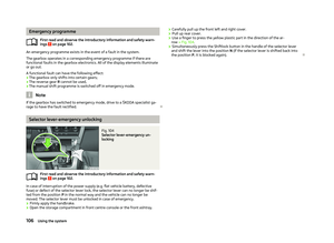 108
108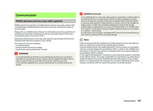 109
109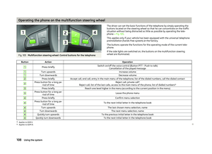 110
110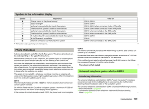 111
111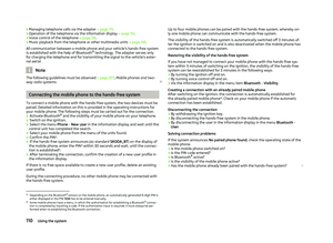 112
112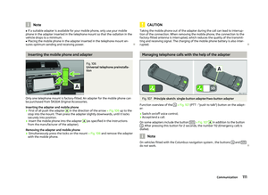 113
113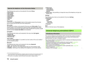 114
114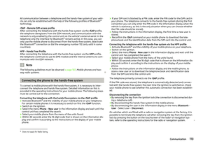 115
115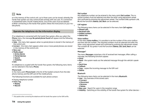 116
116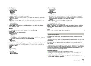 117
117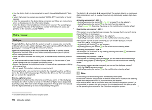 118
118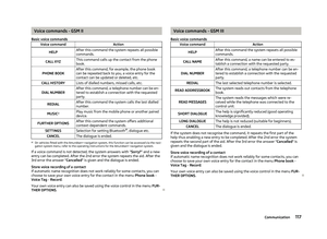 119
119 120
120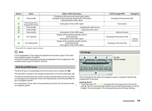 121
121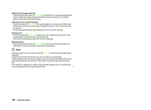 122
122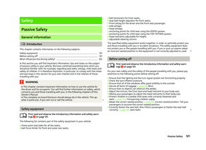 123
123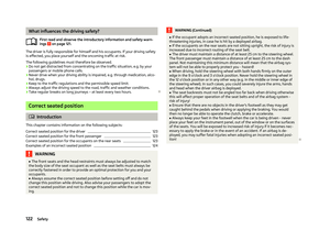 124
124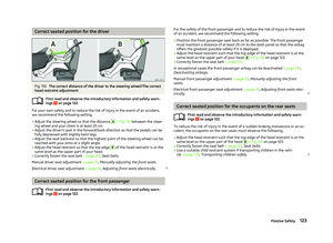 125
125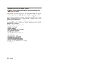 126
126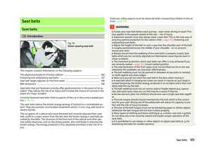 127
127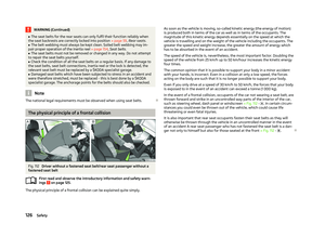 128
128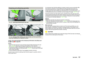 129
129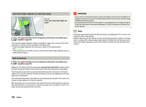 130
130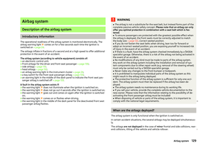 131
131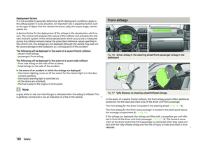 132
132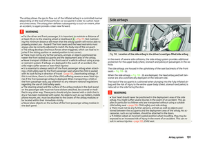 133
133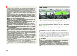 134
134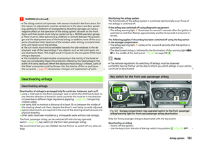 135
135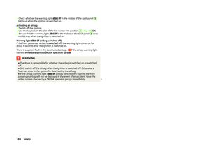 136
136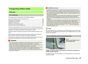 137
137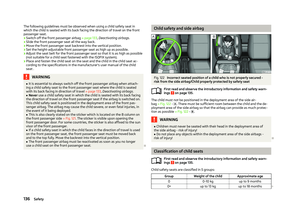 138
138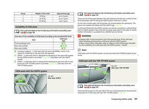 139
139 140
140 141
141 142
142 143
143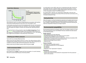 144
144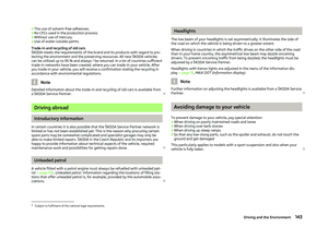 145
145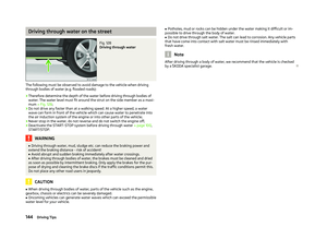 146
146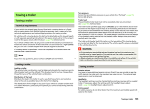 147
147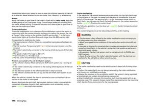 148
148 149
149 150
150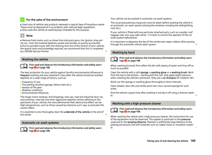 151
151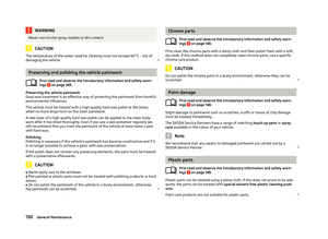 152
152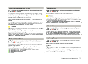 153
153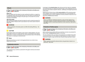 154
154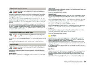 155
155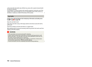 156
156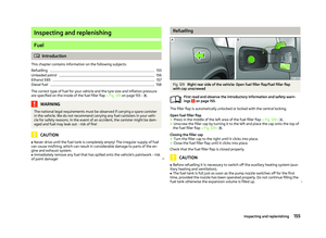 157
157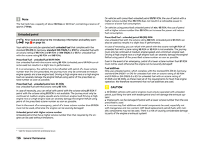 158
158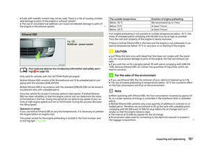 159
159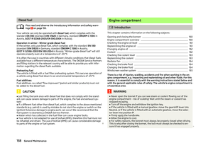 160
160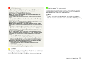 161
161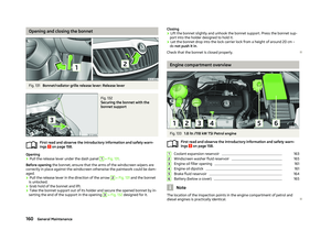 162
162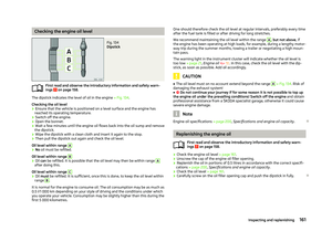 163
163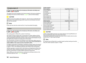 164
164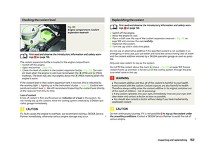 165
165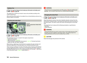 166
166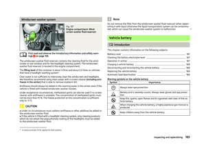 167
167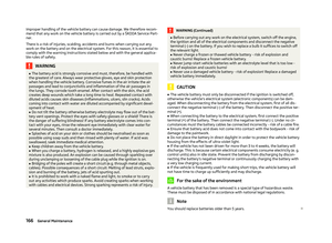 168
168 169
169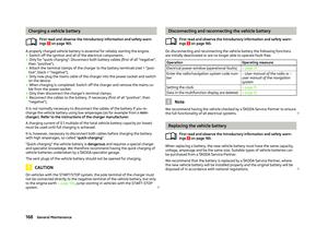 170
170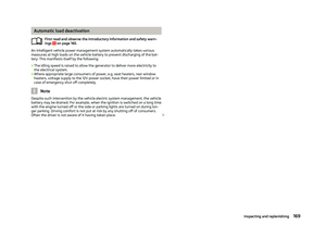 171
171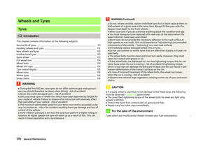 172
172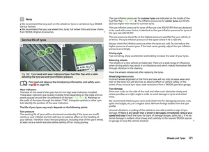 173
173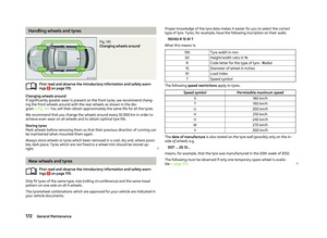 174
174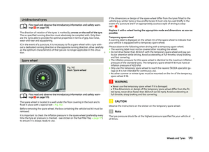 175
175 176
176 177
177 178
178 179
179 180
180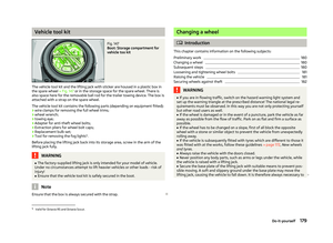 181
181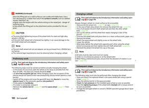 182
182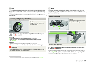 183
183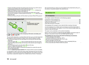 184
184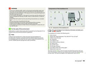 185
185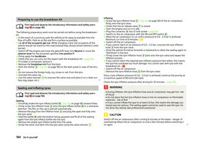 186
186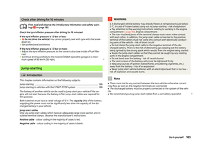 187
187 188
188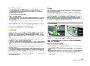 189
189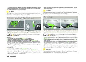 190
190 191
191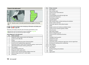 192
192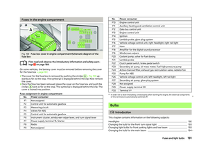 193
193 194
194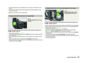 195
195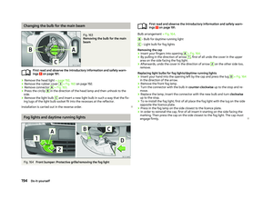 196
196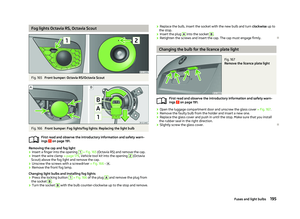 197
197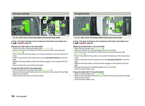 198
198 199
199 200
200 201
201 202
202 203
203 204
204 205
205 206
206 207
207 208
208 209
209 210
210 211
211 212
212 213
213 214
214 215
215 216
216 217
217