Page 1838 of 2896
OIL PAN
EM-29
C
D
E
F
G
H
I
J
K
L
MA
EM
Revision: June 20062007 Versa
9. Apply the sealant without breaks to the specified location using
Tool.
Use Genuine Silicone RTV Sealant or equivalent. Refer to
GI-46, "
Recommended Chemical Products and Sealants" .
10. Tighten bolts in numerical order as shown.
11. Install oil filter with the following procedure:
a. Remove foreign materials adhering to the oil filter installation
surface.
b. Apply new engine oil to the oil seal contact surface of new oil fil-
ter.
c. Screw oil filter manually until it touches the installation surface,
then tighten it by 2/3 turn. Or tighten to specification.
12. Installation of the remaining components is in the reverse order of removal.Tool number WS39930000 ( – )
1 : Oil pan (lower)
: Engine outside
PBIC4590E
: Engine front
PBIC3146J
Oil filter: : 17.7 N·m (1.8 kg-m, 13 ft-lb)
SM A22 9B
Page 1840 of 2896
IGNITION COIL, SPARK PLUG AND ROCKER COVER
EM-31
C
D
E
F
G
H
I
J
K
L
MA
EM
Revision: June 20062007 Versa
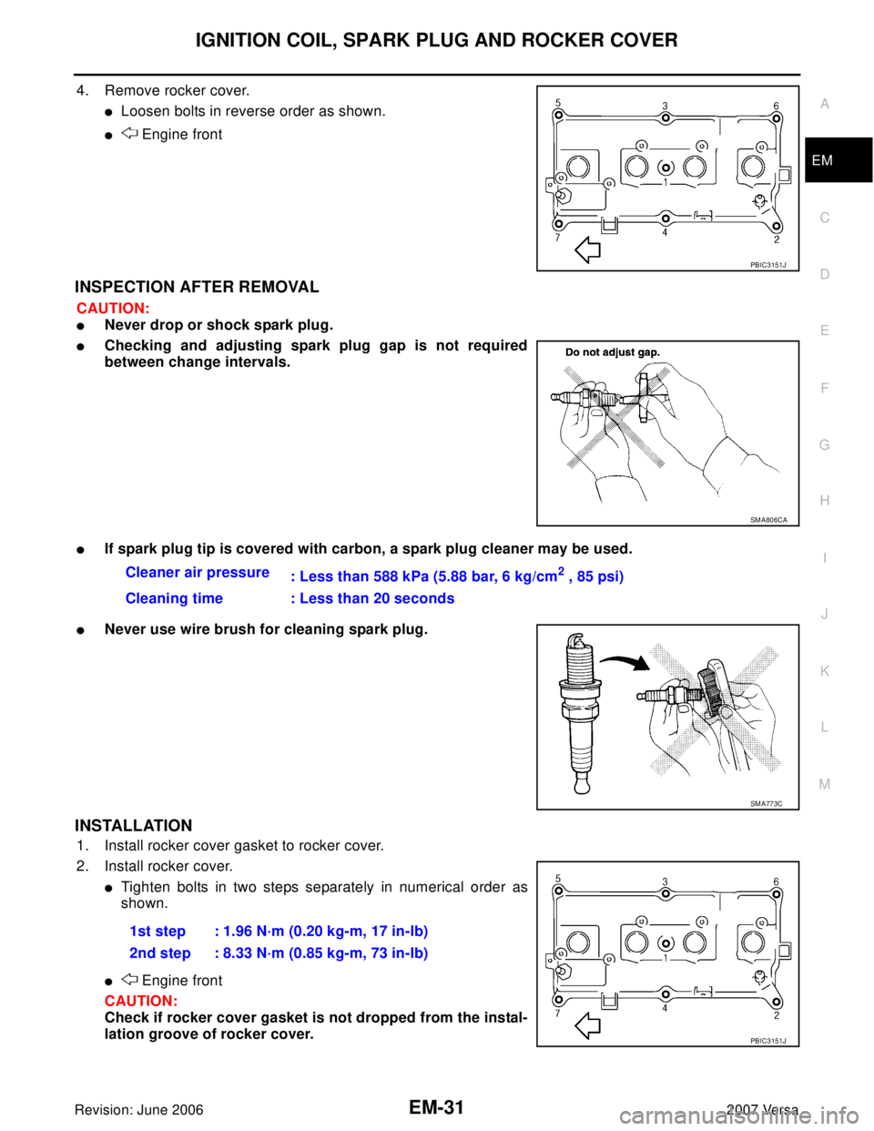
4. Remove rocker cover.
�Loosen bolts in reverse order as shown.
� Engine front
INSPECTION AFTER REMOVAL
CAUTION:
�Never drop or shock spark plug.
�Checking and adjusting spark plug gap is not required
between change intervals.
�If spark plug tip is covered with carbon, a spark plug cleaner may be used.
�Never use wire brush for cleaning spark plug.
INSTALLATION
1. Install rocker cover gasket to rocker cover.
2. Install rocker cover.
�Tighten bolts in two steps separately in numerical order as
shown.
� Engine front
CAUTION:
Check if rocker cover gasket is not dropped from the instal-
lation groove of rocker cover.
PBIC3151J
SM A80 6CA
Cleaner air pressure
: Less than 588 kPa (5.88 bar, 6 kg/cm2 , 85 psi)
Cleaning time : Less than 20 seconds
SM A77 3C
1st step : 1.96 N·m (0.20 kg-m, 17 in-lb)
2nd step : 8.33 N·m (0.85 kg-m, 73 in-lb)
PBIC3151J
Page 1844 of 2896

FUEL INJECTOR AND FUEL TUBE
EM-35
C
D
E
F
G
H
I
J
K
L
MA
EM
Revision: June 20062007 Versa
8. Remove fuel tube.
�Loosen bolts in reverse order as shown.
9. Remove the fuel tube and fuel injector assembly.
CAUTION:
�When removing, be careful to avoid any interference with fuel injector.
�Use a shop cloth to absorb any fuel leaks from fuel tube.
10. Remove fuel injector from fuel tube with the following procedure:
a. Open and remove clip.
b. Remove fuel injector from fuel tube by pulling straight.
CAUTION:
�Be careful with remaining fuel that may go out from fuel tube.
�Be careful not to damage fuel injector nozzle during removal.
�Never bump or drop fuel injector.
�Never disassemble fuel injector.
INSTALLATION
1. Note the following, and install O-rings to fuel injector.
CAUTION:
�Upper and lower O-rings are different. Be careful not to confuse them.
�Handle O-ring with bare hands. Never wear gloves.
�Lubricate O-ring with new engine oil.
�Never clean O-ring with solvent.
�Make sure that O-ring and its mating part are free of foreign material.
�When installing O-ring, be careful not to scratch it with tool or fingernails. Also be careful not to
twist or stretch O-ring. If O-ring was stretched while it was being attached, never insert it quickly
into fuel tube.
�Insert O-ring straight into fuel tube. Never twist it.
: Engine front
PBIC3154J
Fuel tube side : Black
Nozzle side : Green
Page 1845 of 2896
 to fuel tube (1) with the following proce-
dure:
a. Insert clip (2) into clip groove (F) on fuel injector.")
EM-36Revision: June 2006
FUEL INJECTOR AND FUEL TUBE
2007 Versa
2. Install fuel injector (4) to fuel tube (1) with the following proce-
dure:
a. Insert clip (2) into clip groove (F) on fuel injector.
�Insert clip so that protrusion (G) of fuel injector matches cut-
out (D) of clip.
CAUTION:
�Never reuse clip. Replace it with a new one.
�Be careful to keep clip from interfering with O-ring. If
interference occurs, replace O-ring.
b. Insert fuel injector into fuel tube with clip attached.
�Insert it while matching it to the axial center.
�Insert fuel injector so that protrusion (B) of fuel tube matches
cut-out (C) of clip.
�Make sure that fuel tube flange (A) is securely fixed in flange
fixing groove (E) on clip.
c. Make sure that installation is complete by making sure that fuel
injector does not rotate or come off.
3. Set fuel tube and fuel injector assembly at its position for installation on cylinder head.
CAUTION:
For installation, be careful not to interfere with fuel injector nozzle.
4. Tighten bolts in numerical order as shown.
5. Installation of the remaining components is in the reverse order of removal.
3 : O–ring (black)
5 : O–ring (green)
PBIC3155J
: Engine front
PBIC3154J
Page 1847 of 2896

EM-38Revision: June 2006
TIMING CHAIN
2007 Versa
Removal and InstallationEBS00U7N
CAUTION:
The rotating direction indicated in the text indicates all directions seen from the engine front.
REMOVAL
1. Remove front RH wheel. Refer to WT-6, "ROAD WHEEL TIRE ASSEMBLY" .
2. Remove front fender protector (RH). Refer to EI-22, "
FENDER PROTECTOR" .
3. Drain engine oil. Refer to LU-5, "
ENGINE OIL" .
NOTE:
Perform this step when engine is cold.
4. Remove the following parts.
�Rocker cover: Refer to EM-30, "Components" .
�Drive belt: Refer to EM-13, "Components" .
�Water pump pulley: Refer to CO-17, "Components" .
�Ground cable (between engine bracket (RH) and radiator core support)
5. Support the bottom surface of engine using a transmission jack, and then remove the engine bracket and
insulator (RH). Refer to EM-73, "
ENGINE ASSEMBLY" .
6. Set No. 1 cylinder at TDC on its compression stroke with the following procedure:
a. Rotate crankshaft pulley (1) clockwise and align TDC mark (no paint) (B) to timing indicator (A) on front
cover.
b. At the same time, make sure that the cam noses of the No.1 cyl-
inder are located ( ) as shown.
�If not, rotate crankshaft pulley one revolution (360 degrees)
and align as shown.
13.Timing chain tension guide (front
cover side)14. Crankshaft sprocket 15. Oil pump sprocket
16. Oil pump drive chain 17. Camshaft sprocket (INT) 18. Timing chain tension guide
19. O-ring 20. Chain tensioner (for oil pump)
A. Refer to EM-42
B. Refer to EM-51
C : White paint mark (Not use for service)
PBIC3960E
1 : Camshaft (INT)
2 : Camshaft (EXH)
: Engine front
PBIC3359J
Page 1850 of 2896
, and push the slack guide (B) into the inside
of chain tensioner (for oil pump) (1).
�The slack g")
TIMING CHAIN
EM-41
C
D
E
F
G
H
I
J
K
L
MA
EM
Revision: June 20062007 Versa
19. Fully lift up lever (A), and push the slack guide (B) into the inside
of chain tensioner (for oil pump) (1).
�The slack guide is released by fully lifting the lever up. As the
result, the slack guide can be moved.
20. Matching the hole on lever with the hole on tensioner body,
insert a stopper pin (C) to secure slack guide.
NOTE:
Use approximately 1.0 mm (0.04 in) diameter. hard metal pin as
a stopper pin.
21. Remove chain tensioner (for oil pump).
�When the holes on lever and tensioner body cannot be aligned, align these holes by slightly moving the
slack guide.
22. Hold the WAF part of oil pump shaft (A), and then loosen the oil pump sprocket bolt and remove them.
CAUTION:
�Secure the oil pump shaft with the WAF part.
�Never loosen the oil pump sprocket bolt by tightening the
oil pump drive chain.
23. Remove crankshaft sprocket, oil pump sprocket and oil pump drive chain as a set.
24. Remove timing chain tension guide (front cover side) from front cover if necessary.
INSPECTION AFTER REMOVAL
Timing Chain
�Check timing chain and oil pump drive chain for cracks (A) and
any excessive wear (B) at the roller links of timing chain.
�Replace timing chain and/or oil pump drive chain if necessary.
PBIC3453J
1 : Oil pan (upper)
2 : Oil pump
: Engine front
PBIC3539J
PBIC3169J
Page 1852 of 2896
, and then tighten the oil
pump sprocket bolt.
CAUTION:
�Secure the oil pump shaft")
TIMING CHAIN
EM-43
C
D
E
F
G
H
I
J
K
L
MA
EM
Revision: June 20062007 Versa
4. Hold the WAF part of oil pump shaft (A), and then tighten the oil
pump sprocket bolt.
CAUTION:
�Secure the oil pump shaft with the WAF part.
�Never loosen the oil pump sprocket bolt by tightening the
oil pump drive chain.
5. Install chain tensioner (for oil pump) (1).
�Fix the plunger at the most compressed position using a stop-
per pin (A), and then install it.
�Securely pull out ( ) the stopper pin after installing the chain
tensioner (for oil pump).
�Check matching mark position of oil pump drive chain and
each sprocket again.
6. Align the matching marks of each sprocket with the matching
marks of timing chain.
NOTE:
*: There are 2 outer grooves in camshaft sprocket (INT). The
wider one is a matching mark.
�If these matching marks are not aligned, rotate the camshaft
slightly by holding the hexagonal portion to correct the posi-
tion.
CAUTION:
Check matching mark position of each sprocket and timing
chain again after installing the timing chain.
1 : Oil pan (upper)
2 : Oil pump
: Engine front
PBIC3539J
PBIC3456J
1 : Camshaft sprocket (EXH)
2 : Camshaft sprocket (INT)
3 : Timing chain
A : Matching mark (dark blue link)
B : Matching mark (stamping)
C : Matching mark (outer groove*)
D : Matching mark (gold link)
E : Matching mark (stamping)
PBIC3172J
Page 1853 of 2896
 and the timing chain
slack guide (2).
8. Install timing chain tensioner (1).
�Fix the plunger at the most")
EM-44Revision: June 2006
TIMING CHAIN
2007 Versa
7. Install the timing chain tension guide (3) and the timing chain
slack guide (2).
8. Install timing chain tensioner (1).
�Fix the plunger at the most compressed position using a stop-
per pin (A), and then install it.
�Securely pull out the stopper pin after installing the timing
chain tensioner.
9. Check matching mark position of timing chain and each sprocket again.
10. Apply new engine oil to new front oil seal joint surface.
11. Using a suitable tool install front oil seal so that each seal lip is oriented as shown.
�Press-fit front oil seal until it is flush with front end surface of
front cover as shown below with a suitable tool.
CAUTION:
�Be careful not to damage front cover and crankshaft.
�Press-fit oil seal straight to avoid causing burrs or tilting.
�Never touch grease applied onto oil seal lip.
12. Install new O-ring to cylinder block.
1 : Timing chain
PBIC3166J
PBIC3165J
A : Dust seal lip
B: Oil seal lip
: Engine front
: Engine rear
Within 0.3 mm (0.012 in) toward engine front
Within 0.5 mm (0.020 in) toward engine rear
PBIC3485J