Page 1814 of 2896

PRECAUTIONS
EM-5
C
D
E
F
G
H
I
J
K
L
MA
EM
Revision: June 20062007 Versa
�Do not use a torque value for final tightening.
�The torque value for these parts are for a preliminary step.
�Ensure thread and seat surfaces are clean and coated with engine oil.
Precautions for Liquid GasketEBS00U6Y
REMOVAL OF LIQUID GASKET SEALING
�After removing the bolts and nuts, separate the mating surface
and remove the sealant using Tool.
CAUTION:
Be careful not to damage the mating surfaces.
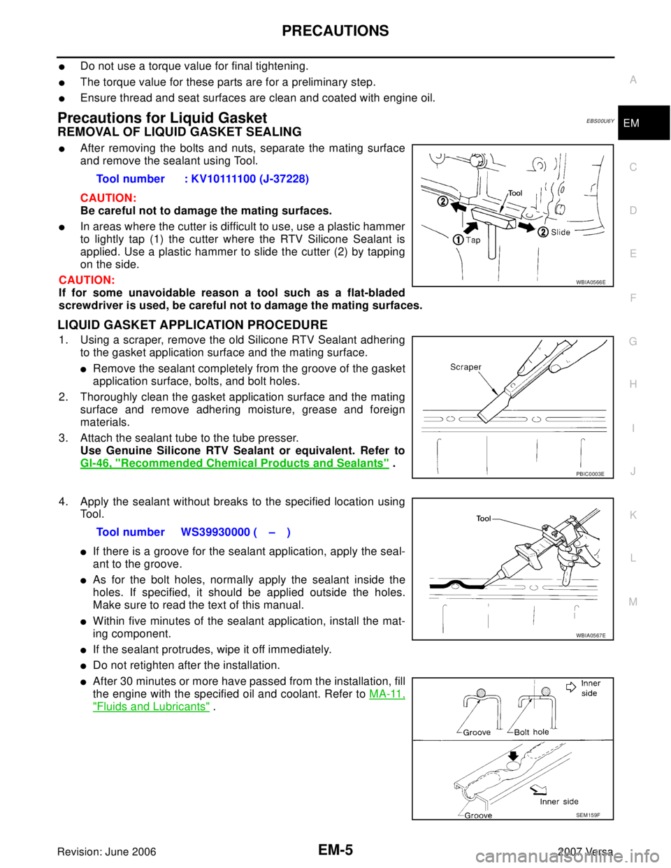
�In areas where the cutter is difficult to use, use a plastic hammer
to lightly tap (1) the cutter where the RTV Silicone Sealant is
applied. Use a plastic hammer to slide the cutter (2) by tapping
on the side.
CAUTION:
If for some unavoidable reason a tool such as a flat-bladed
screwdriver is used, be careful not to damage the mating surfaces.
LIQUID GASKET APPLICATION PROCEDURE
1. Using a scraper, remove the old Silicone RTV Sealant adhering
to the gasket application surface and the mating surface.
�Remove the sealant completely from the groove of the gasket
application surface, bolts, and bolt holes.
2. Thoroughly clean the gasket application surface and the mating
surface and remove adhering moisture, grease and foreign
materials.
3. Attach the sealant tube to the tube presser.
Use Genuine Silicone RTV Sealant or equivalent. Refer to
GI-46, "
Recommended Chemical Products and Sealants" .
4. Apply the sealant without breaks to the specified location using
Tool.
�If there is a groove for the sealant application, apply the seal-
ant to the groove.
�As for the bolt holes, normally apply the sealant inside the
holes. If specified, it should be applied outside the holes.
Make sure to read the text of this manual.
�Within five minutes of the sealant application, install the mat-
ing component.
�If the sealant protrudes, wipe it off immediately.
�Do not retighten after the installation.
�After 30 minutes or more have passed from the installation, fill
the engine with the specified oil and coolant. Refer to MA-11,
"Fluids and Lubricants" . Tool number : KV10111100 (J-37228)
WBIA0566E
PBIC0003E
Tool number WS39930000 ( – )
WBIA0567E
SEM 15 9F
Page 1820 of 2896
NOISE, VIBRATION AND HARSHNESS (NVH) TROUBLESHOOTING
EM-11
C
D
E
F
G
H
I
J
K
L
MA
EM
Revision: June 20062007 Versa
NOISE, VIBRATION AND HARSHNESS (NVH) TROUBLESHOOTINGPFP:00003
NVH Troubleshooting — Engine NoiseEBS00T5P
WBIA0769E
Page 1821 of 2896

EM-12Revision: June 2006
NOISE, VIBRATION AND HARSHNESS (NVH) TROUBLESHOOTING
2007 Versa
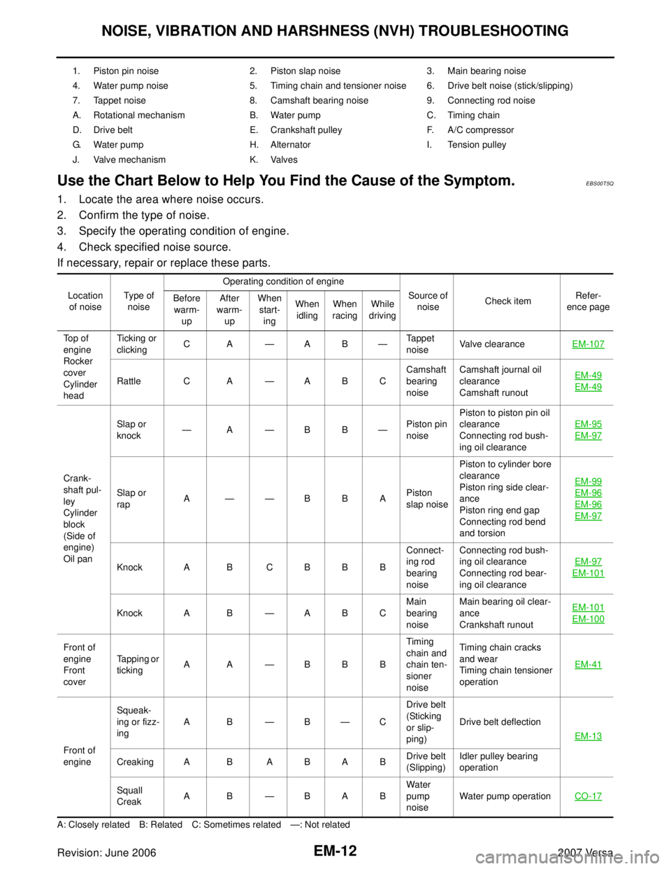
Use the Chart Below to Help You Find the Cause of the Symptom.EBS00T5Q
1. Locate the area where noise occurs.
2. Confirm the type of noise.
3. Specify the operating condition of engine.
4. Check specified noise source.
If necessary, repair or replace these parts.
A: Closely related B: Related C: Sometimes related —: Not related1. Piston pin noise 2. Piston slap noise 3. Main bearing noise
4. Water pump noise 5. Timing chain and tensioner noise 6. Drive belt noise (stick/slipping)
7. Tappet noise 8. Camshaft bearing noise 9. Connecting rod noise
A. Rotational mechanism B. Water pump C. Timing chain
D. Drive belt E. Crankshaft pulley F. A/C compressor
G. Water pump H. Alternator I. Tension pulley
J. Valve mechanism K. Valves
Location
of noiseType of
noiseOperating condition of engine
Source of
noiseCheck itemRefer-
ence page Before
warm-
upAfter
warm-
upWhen
start-
ingWhen
idlingWhen
racingWhile
driving
Top of
engine
Rocker
cover
Cylinder
headTick ing or
clickingCA—AB—Tappet
noiseValve clearanceEM-107
Rattle C A —ABCCamshaft
bearing
noiseCamshaft journal oil
clearance
Camshaft runoutEM-49EM-49
Crank-
shaft pul-
ley
Cylinder
block
(Side of
engine)
Oil panSlap or
knock—A—BB—Piston pin
noisePiston to piston pin oil
clearance
Connecting rod bush-
ing oil clearanceEM-95
EM-97
Slap or
rapA——BBAPiston
slap noisePiston to cylinder bore
clearance
Piston ring side clear-
ance
Piston ring end gap
Connecting rod bend
and torsionEM-99EM-96
EM-96
EM-97
Knock A B C B B BConnect-
ing rod
bearing
noiseConnecting rod bush-
ing oil clearance
Connecting rod bear-
ing oil clearanceEM-97EM-101
Knock A B —ABCMain
bearing
noiseMain bearing oil clear-
ance
Crankshaft runoutEM-101EM-100
Front of
engine
Front
coverTapping or
tickingAA—BBBTiming
chain and
chain ten-
sioner
noiseTiming chain cracks
and wear
Timing chain tensioner
operationEM-41
Front of
engineSqueak-
ing or fizz-
ingAB—B—CDrive belt
(Sticking
or slip-
ping)Drive belt deflection
EM-13
Creaking A B A B A BDrive belt
(Slipping)Idler pulley bearing
operation
Squall
CreakAB—BABWater
pump
noiseWater pump operationCO-17
Page 1822 of 2896

DRIVE BELTS
EM-13
C
D
E
F
G
H
I
J
K
L
MA
EM
Revision: June 20062007 Versa
DRIVE BELTSPFP:02117
ComponentsEBS00U6Z
Checking Drive BeltsEBS00U70
WA RN ING:
Be sure to perform this step when the engine is stopped.
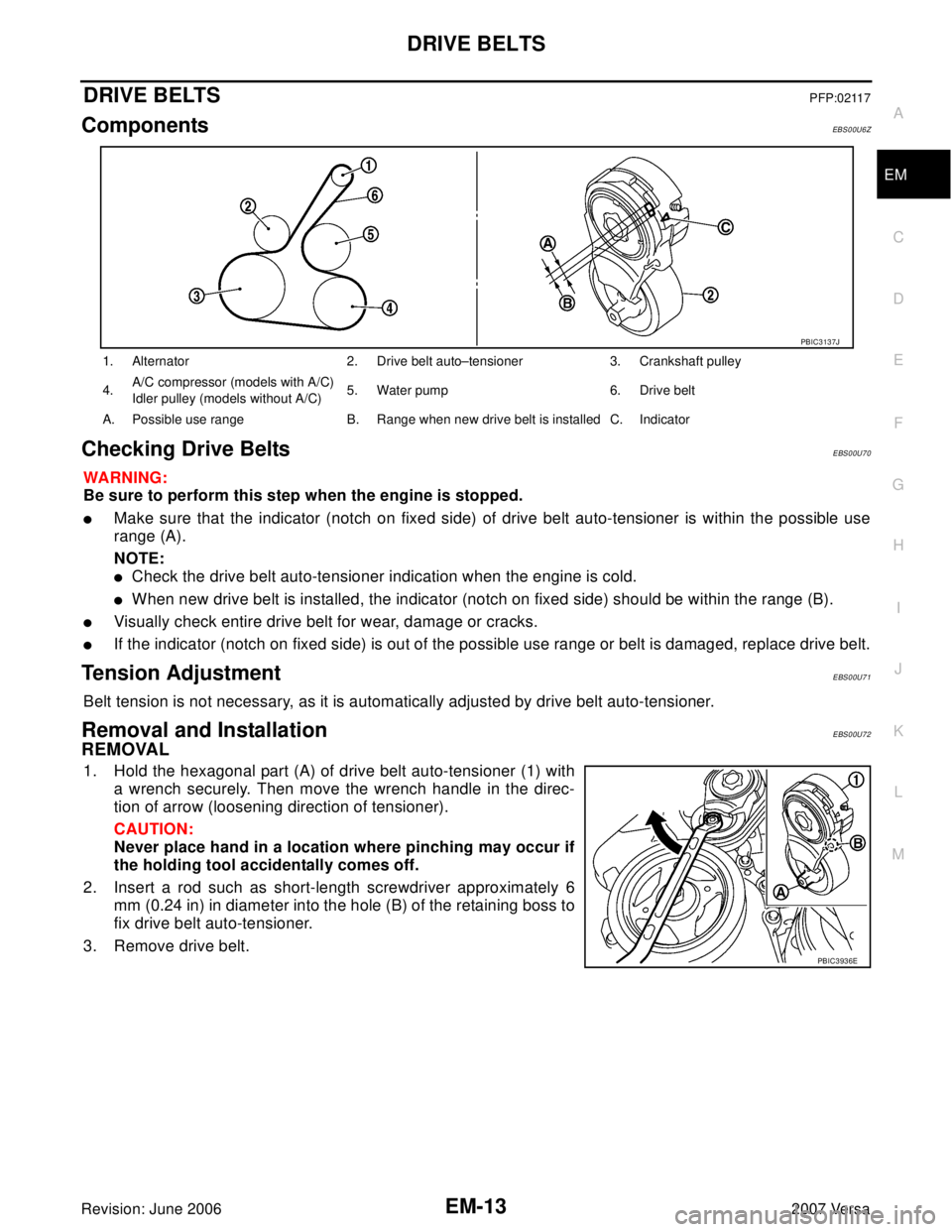
�Make sure that the indicator (notch on fixed side) of drive belt auto-tensioner is within the possible use
range (A).
NOTE:
�Check the drive belt auto-tensioner indication when the engine is cold.
�When new drive belt is installed, the indicator (notch on fixed side) should be within the range (B).
�Visually check entire drive belt for wear, damage or cracks.
�If the indicator (notch on fixed side) is out of the possible use range or belt is damaged, replace drive belt.
Tension AdjustmentEBS00U71
Belt tension is not necessary, as it is automatically adjusted by drive belt auto-tensioner.
Removal and InstallationEBS00U72
REMOVAL
1. Hold the hexagonal part (A) of drive belt auto-tensioner (1) with
a wrench securely. Then move the wrench handle in the direc-
tion of arrow (loosening direction of tensioner).
CAUTION:
Never place hand in a location where pinching may occur if
the holding tool accidentally comes off.
2. Insert a rod such as short-length screwdriver approximately 6
mm (0.24 in) in diameter into the hole (B) of the retaining boss to
fix drive belt auto-tensioner.
3. Remove drive belt.
1. Alternator 2. Drive belt auto–tensioner 3. Crankshaft pulley
4.A/C compressor (models with A/C)
Idler pulley (models without A/C)5. Water pump 6. Drive belt
A. Possible use range B. Range when new drive belt is installed C. Indicator
PBIC3137J
PBIC3936E
Page 1823 of 2896

EM-14Revision: June 2006
DRIVE BELTS
2007 Versa
INSTALLATION
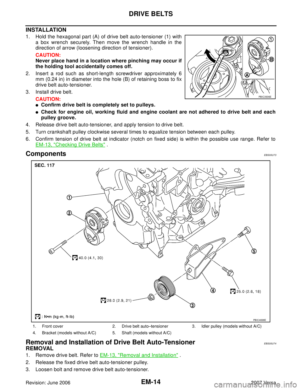
1. Hold the hexagonal part (A) of drive belt auto-tensioner (1) with
a box wrench securely. Then move the wrench handle in the
direction of arrow (loosening direction of tensioner).
CAUTION:
Never place hand in a location where pinching may occur if
the holding tool accidentally comes off.
2. Insert a rod such as short-length screwdriver approximately 6
mm (0.24 in) in diameter into the hole (B) of retaining boss to fix
drive belt auto-tensioner.
3. Install drive belt.
CAUTION:
�Confirm drive belt is completely set to pulleys.
�Check for engine oil, working fluid and engine coolant are not adhered to drive belt and each
pulley groove.
4. Release drive belt auto-tensioner, and apply tension to drive belt.
5. Turn crankshaft pulley clockwise several times to equalize tension between each pulley.
6. Confirm tension of drive belt at indicator (notch on fixed side) is within the possible use range. Refer to
EM-13, "
Checking Drive Belts" .
ComponentsEBS00U73
Removal and Installation of Drive Belt Auto-TensionerEBS00U74
REMOVAL
1. Remove drive belt. Refer to EM-13, "Removal and Installation" .
2. Release the fixed drive belt auto-tensioner pulley.
3. Loosen bolt and remove drive belt auto-tensioner.
PBIC3936E
1. Front cover 2. Drive belt auto–tensioner 3. Idler pulley (models without A/C)
4. Bracket (models without A/C) 5. Shaft (models without A/C)
PBIC4698E
Page 1827 of 2896
EM-18Revision: June 2006
INTAKE MANIFOLD
2007 Versa
INTAKE MANIFOLDPFP:14003
ComponentsEBS00U7C
Removal and InstallationEBS00U7D
REMOVAL
1. Remove engine cover (1).
2. Drain engine coolant. Refer to CO-8, "
DRAINING ENGINE
COOLANT" .
CAUTION:
Perform this step when engine is cold.
NOTE:
This step is unnecessary when putting plugs to water hoses (to
electronic throttle control actuator)
a. Disconnect water hoses from electronic throttle control actuator.
b. Remove electronic throttle control actuator.
CAUTION:
�Handle carefully to avoid any shock to electric throttle control actuator.
�Never disassemble.
3. Remove oil level gauge.
CAUTION:
Cover the oil level gauge guide openings to avoid entry of foreign materials.
1. Hose clamp 2. Bracket 3. PCV hose
4. Gasket 5. Intake manifold 6. O-ring
7.EVAP canister purge volume control
solenoid valve8. Electric throttle control actuator 9. Gasket
WBIA0771E
WBIA0777E
Page 1828 of 2896
INTAKE MANIFOLD
EM-19
C
D
E
F
G
H
I
J
K
L
MA
EM
Revision: June 20062007 Versa
4. Loosen and remove intake manifold (1) bolts (A) (B).
5. Loosen bolts in reverse order as shown.
CAUTION:
Cover engine openings to avoid entry of foreign materials.
6. Remove EVAP canister purge volume control solenoid valve
from intake manifold, if necessary.
CAUTION:
Handle it carefully and avoid impacts.
7. Remove intake manifold.
INSTALLATION
1. Install intake manifold.
NOTE:
Be sure the intake manifold gasket is seated correctly in groove of intake manifold.
2. Tighten bolts in numerical order as shown.
: Engine front
PBIC3939E
: Engine front
PBIC3527J
: Engine front
WBIA0788E
Page 1829 of 2896
EM-20Revision: June 2006
INTAKE MANIFOLD
2007 Versa
3. Tighten intake manifold bolt (A). Then tighten intake manifold
bolt (B).
4. Install electronic throttle control actuator
5. Install water hoses (3), (5) to electronic throttle control actuator
as shown.
6. Installation of the remaining components is in the reverse order of removal.
INSPECTION AFTER INSTALLATION
�Check for leaks of engine coolant. Refer to CO-8, "CHECKING COOLING SYSTEM FOR LEAKS" .
�Start and warm up the engine. Visually check for engine coolant leaks.
1 : Intake manifold
: Engine front
PBIC3939E
1 : Electric throttle control actuator
2: Clamp
4 : Water outlet
A: Paint Mark
B : The clamp shall not interfere with the bulged section.
PBIC4703E