Page 206 of 2896
TROUBLE DIAGNOSIS FOR SYMPTOMS
AT-193
D
E
F
G
H
I
J
K
L
MA
B
AT
Revision: June 20062007 Versa
TROUBLE DIAGNOSIS FOR SYMPTOMSPFP:00007
Wiring Diagram — AT — NONDTCUCS005UV
BCWA0662E
Page 211 of 2896

AT-198
TROUBLE DIAGNOSIS FOR SYMPTOMS
Revision: June 20062007 Versa
OD OFF Indicator Lamp Does Not Come OnUCS005UW
SYMPTOM:
OD OFF indicator lamp does not come on for about 2 seconds when turning ignition switch to ON.
DIAGNOSTIC PROCEDURE
1. CHECK CAN COMMUNICATION LINE
Perform self-diagnosis. Refer to AT- 8 2 , "
SELF-DIAGNOSTIC RESULT MODE" .
Is a malfunction in CAN communication indicated in the results?
YES >> Check CAN communication line. Refer to AT-94, "DTC U1000 CAN COMMUNICATION LINE" .
NO >> GO TO 2.
2. CHECK TCM POWER SOURCE
1. Turn ignition switch ON. (Do not start engine.)
2. Check voltage between TCM connector terminals and ground.
Refer to AT-183, "
Wiring Diagram — AT — MAIN" .
3. Turn ignition switch OFF.
4. Check voltage between TCM connector terminals and ground.
OK or NG
OK >> GO TO 4.
NG >> GO TO 3.
3. DETECT MALFUNCTIONING ITEM
Check the following.
�Harness for short or open between ignition switch and TCM connector terminals 10, 19. Refer to AT-183,
"Wiring Diagram — AT — MAIN" .
�Harness for short or open between battery and TCM connector terminal 28. Refer to AT-183, "Wiring Dia-
gram — AT — MAIN" .
�10A fuse (No.13, located in the fuse block) and 10A fuse (No.49, located in the IPDM E/R). Refer to AT -
183, "Wiring Diagram — AT — MAIN" .
�Ignition switch. Refer to PG-4, "POWER SUPPLY ROUTING CIRCUIT" .
OK or NG
OK >> GO TO 4.
NG >> Repair or replace damaged parts.
Item Connector Terminal Judgement standard (Approx.)
TCM connectorE3110 -
Ground
Battery voltage 19 -
Ground
E3228 -
Ground
SCIA2656E
Item Connector Terminal Judgement standard (Approx.)
TCM connectorE3110 -
Ground0V
19 -
Ground0V
E3228 -
GroundBattery voltage
SCIA2657E
Page 212 of 2896
TROUBLE DIAGNOSIS FOR SYMPTOMS
AT-199
D
E
F
G
H
I
J
K
L
MA
B
AT
Revision: June 20062007 Versa
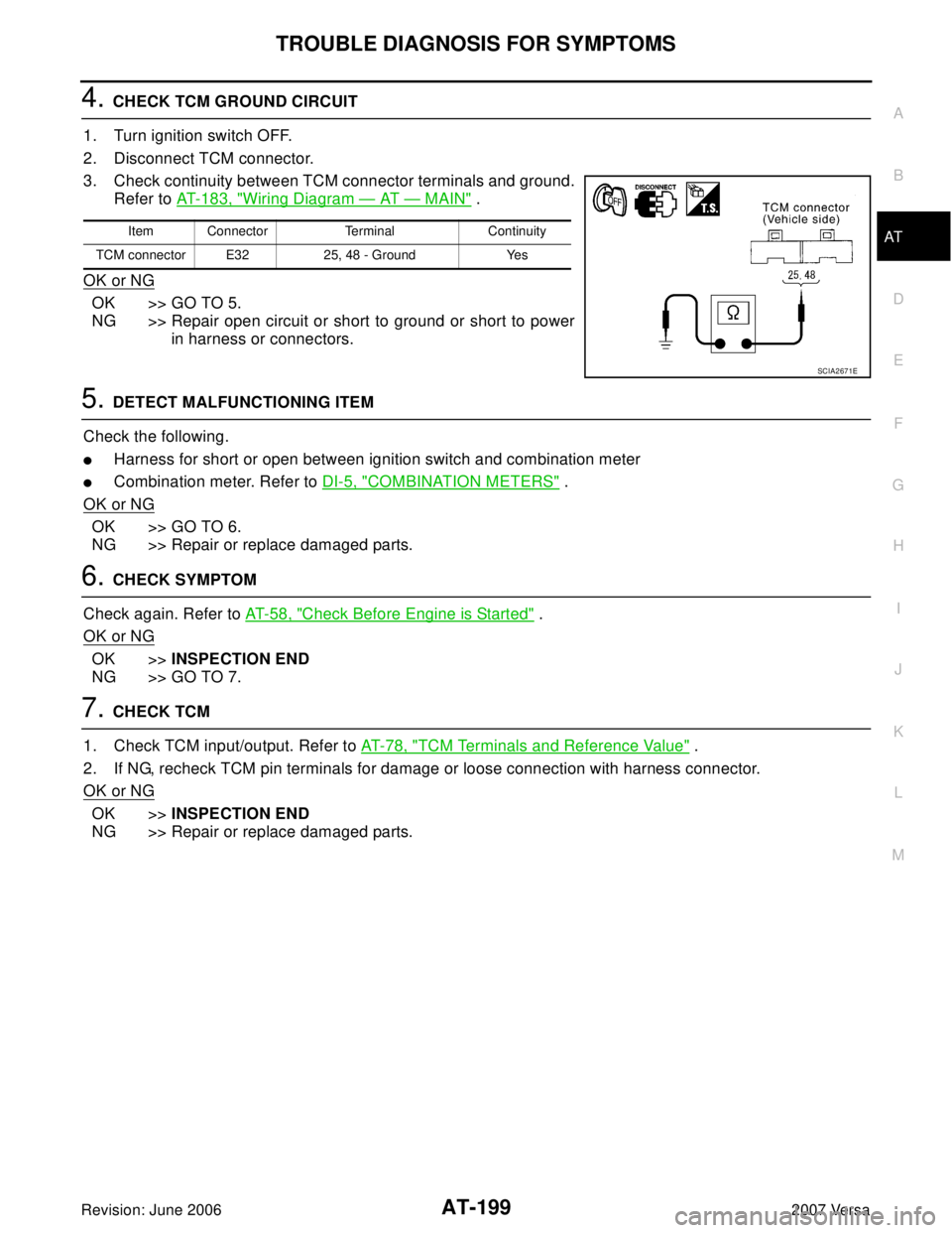
4. CHECK TCM GROUND CIRCUIT
1. Turn ignition switch OFF.
2. Disconnect TCM connector.
3. Check continuity between TCM connector terminals and ground.
Refer to AT- 1 8 3 , "
Wiring Diagram — AT — MAIN" .
OK or NG
OK >> GO TO 5.
NG >> Repair open circuit or short to ground or short to power
in harness or connectors.
5. DETECT MALFUNCTIONING ITEM
Check the following.
�Harness for short or open between ignition switch and combination meter
�Combination meter. Refer to DI-5, "COMBINATION METERS" .
OK or NG
OK >> GO TO 6.
NG >> Repair or replace damaged parts.
6. CHECK SYMPTOM
Check again. Refer to AT- 5 8 , "
Check Before Engine is Started" .
OK or NG
OK >>INSPECTION END
NG >> GO TO 7.
7. CHECK TCM
1. Check TCM input/output. Refer to AT-78, "
TCM Terminals and Reference Value" .
2. If NG, recheck TCM pin terminals for damage or loose connection with harness connector.
OK or NG
OK >>INSPECTION END
NG >> Repair or replace damaged parts.
Item Connector Terminal Continuity
TCM connector E32 25, 48 - Ground Yes
SCIA2671E
Page 213 of 2896
AT-200
TROUBLE DIAGNOSIS FOR SYMPTOMS
Revision: June 20062007 Versa
Engine Cannot Be Started in “P” and “N” PositionUCS005UX
SYMPTOM:
�Engine cannot be started with selector lever in “P” or “N” position.
�Engine can be started with selector lever in “D”, “2”, “1” or “R” position.
DIAGNOSTIC PROCEDURE
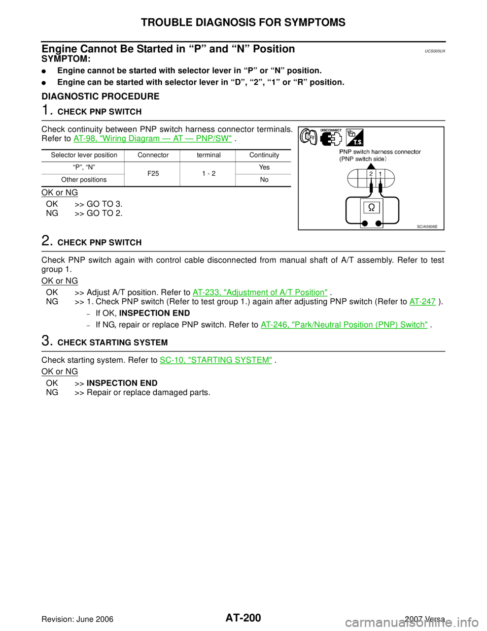
1. CHECK PNP SWITCH
Check continuity between PNP switch harness connector terminals.
Refer to AT-98, "
Wiring Diagram — AT — PNP/SW" .
OK or NG
OK >> GO TO 3.
NG >> GO TO 2.
2. CHECK PNP SWITCH
Check PNP switch again with control cable disconnected from manual shaft of A/T assembly. Refer to test
group 1.
OK or NG
OK >> Adjust A/T position. Refer to AT- 2 3 3 , "Adjustment of A/T Position" .
NG >> 1. Check PNP switch (Refer to test group 1.) again after adjusting PNP switch (Refer to AT-247
).
–If OK, INSPECTION END
–If NG, repair or replace PNP switch. Refer to AT-246, "Park/Neutral Position (PNP) Switch" .
3. CHECK STARTING SYSTEM
Check starting system. Refer to SC-10, "
STARTING SYSTEM" .
OK or NG
OK >>INSPECTION END
NG >> Repair or replace damaged parts.
Selector lever position Connector terminal Continuity
“P”, “N”
F25 1 - 2Ye s
Other positions No
SCIA5606E
Page 232 of 2896
TROUBLE DIAGNOSIS FOR SYMPTOMS
AT-219
D
E
F
G
H
I
J
K
L
MA
B
AT
Revision: June 20062007 Versa
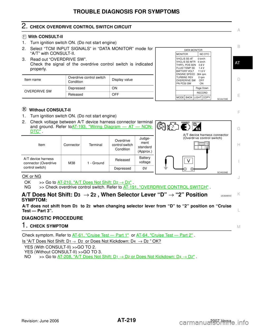
2. CHECK OVERDRIVE CONTROL SWITCH CIRCUIT
With CONSULT-II
1. Turn ignition switch ON. (Do not start engine)
2. Select “TCM INPUT SIGNALS” in “DATA MONITOR” mode for
“A/T” with CONSULT-II.
3. Read out “OVERDRIVE SW”.
Check the signal of the overdrive control switch is indicated
properly.
Without CONSULT-II
1. Turn ignition switch ON. (Do not start engine)
2. Check voltage between A/T device harness connector terminal
and ground. Refer toAT-193, "
Wiring Diagram — AT — NON-
DTC" .
OK or NG
OK >> Go to AT- 2 1 0 , "A/T Does Not Shift: D2 → D3" .
NG >> Check overdrive control switch. Refer to AT - 1 9 1 , "
OVERDRIVE CONTROL SWITCH" .
A/T Does Not Shift: D3 → 22 , When Selector Lever “D” → “2” PositionUCS005VC
SYMPTOM:
A/T does not shift from D3 to 22 when changing selector lever from “D” to “2” position on “Cruise
Test — Part 3”.
DIAGNOSTIC PROCEDURE
1. CHECK SYMPTOM
Check symptom. Refer to AT - 6 1 , "
Cruise Test — Part 1" or AT- 6 4 , "Cruise Test — Part 2" .
Is
“A/T Does Not Shift: D1 → D2 or Does Not Kickdown: D4 → D2 ” OK?
YES (With CONSULT-II) >>GO TO 2.
YES (Without CONSULT-II) >>GO TO 3.
NO >> Go to AT- 2 0 8 , "
A/T Does Not Shift: D1 → D2 or Does Not Kickdown: D4 → D2" .
Item nameOverdrive control switch
ConditionDisplay value
OVERDRIVE SWDepressed ON
Released OFF
SCIA4730E
Item Connector TerminalOverdrive
control switch
ConditionJudge-
ment
standard
(Approx.)
A/T device harness
connector (Overdrive
control switch)M38 1 - GroundReleasedBattery
voltage
Depressed 0V
SCIA5336E
Page 233 of 2896
AT-220
TROUBLE DIAGNOSIS FOR SYMPTOMS
Revision: June 20062007 Versa
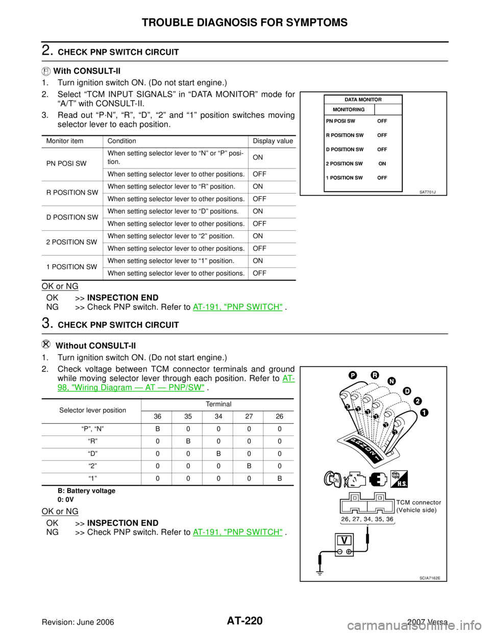
2. CHECK PNP SWITCH CIRCUIT
With CONSULT-II
1. Turn ignition switch ON. (Do not start engine.)
2. Select “TCM INPUT SIGNALS” in “DATA MONITOR” mode for
“A/T” with CONSULT-II.
3. Read out “P·N”, “R”, “D”, “2” and “1” position switches moving
selector lever to each position.
OK or NG
OK >>INSPECTION END
NG >> Check PNP switch. Refer to AT - 1 9 1 , "
PNP SWITCH" .
3. CHECK PNP SWITCH CIRCUIT
Without CONSULT-II
1. Turn ignition switch ON. (Do not start engine.)
2. Check voltage between TCM connector terminals and ground
while moving selector lever through each position. Refer to AT-
98, "Wiring Diagram — AT — PNP/SW" .
B: Battery voltage
0: 0V
OK or NG
OK >>INSPECTION END
NG >> Check PNP switch. Refer to AT - 1 9 1 , "
PNP SWITCH" .
Monitor item Condition Display value
PN POSI SWWhen setting selector lever to “N” or “P” posi-
tion.ON
When setting selector lever to other positions. OFF
R POSITION SWWhen setting selector lever to “R” position. ON
When setting selector lever to other positions. OFF
D POSITION SWWhen setting selector lever to “D” positions. ON
When setting selector lever to other positions. OFF
2 POSITION SWWhen setting selector lever to “2” position. ON
When setting selector lever to other positions. OFF
1 POSITION SWWhen setting selector lever to “1” position. ON
When setting selector lever to other positions. OFF
SAT7 0 1J
Selector lever positionTerminal
36 35 34 27 26
“P”, “N” B 0 0 0 0
“R” 0B000
“D” 0 0 B 0 0
“2” 0 0 0 B 0
“1” 0 0 0 0 B
SCIA7162E
Page 235 of 2896
AT-222
TROUBLE DIAGNOSIS FOR SYMPTOMS
Revision: June 20062007 Versa
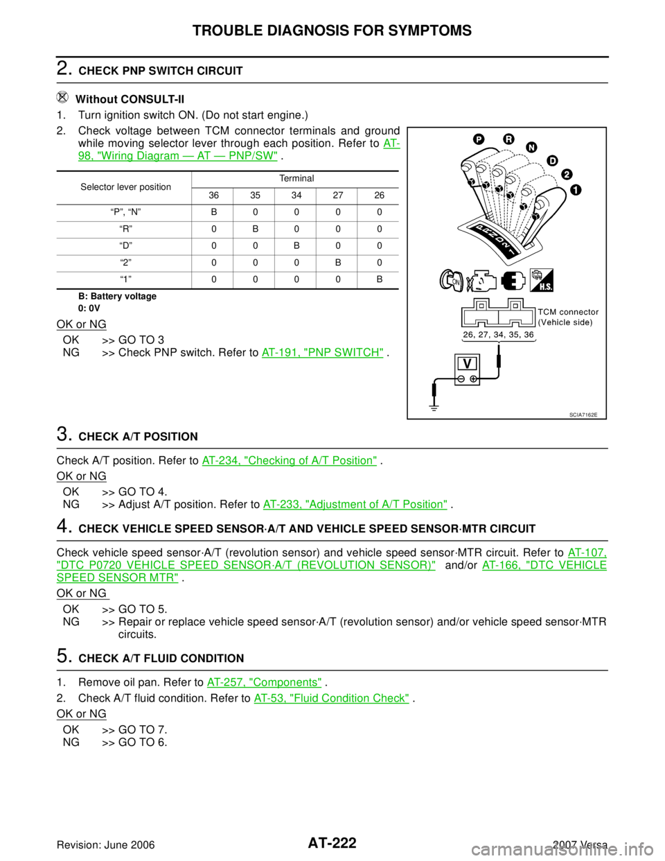
2. CHECK PNP SWITCH CIRCUIT
Without CONSULT-II
1. Turn ignition switch ON. (Do not start engine.)
2. Check voltage between TCM connector terminals and ground
while moving selector lever through each position. Refer to AT-
98, "Wiring Diagram — AT — PNP/SW" .
B: Battery voltage
0: 0V
OK or NG
OK >> GO TO 3
NG >> Check PNP switch. Refer to AT - 1 9 1 , "
PNP SWITCH" .
3. CHECK A/T POSITION
Check A/T position. Refer to AT-234, "
Checking of A/T Position" .
OK or NG
OK >> GO TO 4.
NG >> Adjust A/T position. Refer to AT- 2 3 3 , "
Adjustment of A/T Position" .
4. CHECK VEHICLE SPEED SENSOR·A/T AND VEHICLE SPEED SENSOR·MTR CIRCUIT
Check vehicle speed sensor·A/T (revolution sensor) and vehicle speed sensor·MTR circuit. Refer to AT-107,
"DTC P0720 VEHICLE SPEED SENSOR·A/T (REVOLUTION SENSOR)" and/or AT-166, "DTC VEHICLE
SPEED SENSOR MTR" .
OK or NG
OK >> GO TO 5.
NG >> Repair or replace vehicle speed sensor·A/T (revolution sensor) and/or vehicle speed sensor·MTR
circuits.
5. CHECK A/T FLUID CONDITION
1. Remove oil pan. Refer to AT-257, "
Components" .
2. Check A/T fluid condition. Refer to AT- 5 3 , "
Fluid Condition Check" .
OK or NG
OK >> GO TO 7.
NG >> GO TO 6.
Selector lever positionTerminal
36 35 34 27 26
“P”, “N” B 0 0 0 0
“R” 0B000
“D” 0 0 B 0 0
“2” 0 0 0 B 0
“1” 0 0 0 0 B
SCIA7162E
Page 237 of 2896
AT-224
TROUBLE DIAGNOSIS FOR SYMPTOMS
Revision: June 20062007 Versa
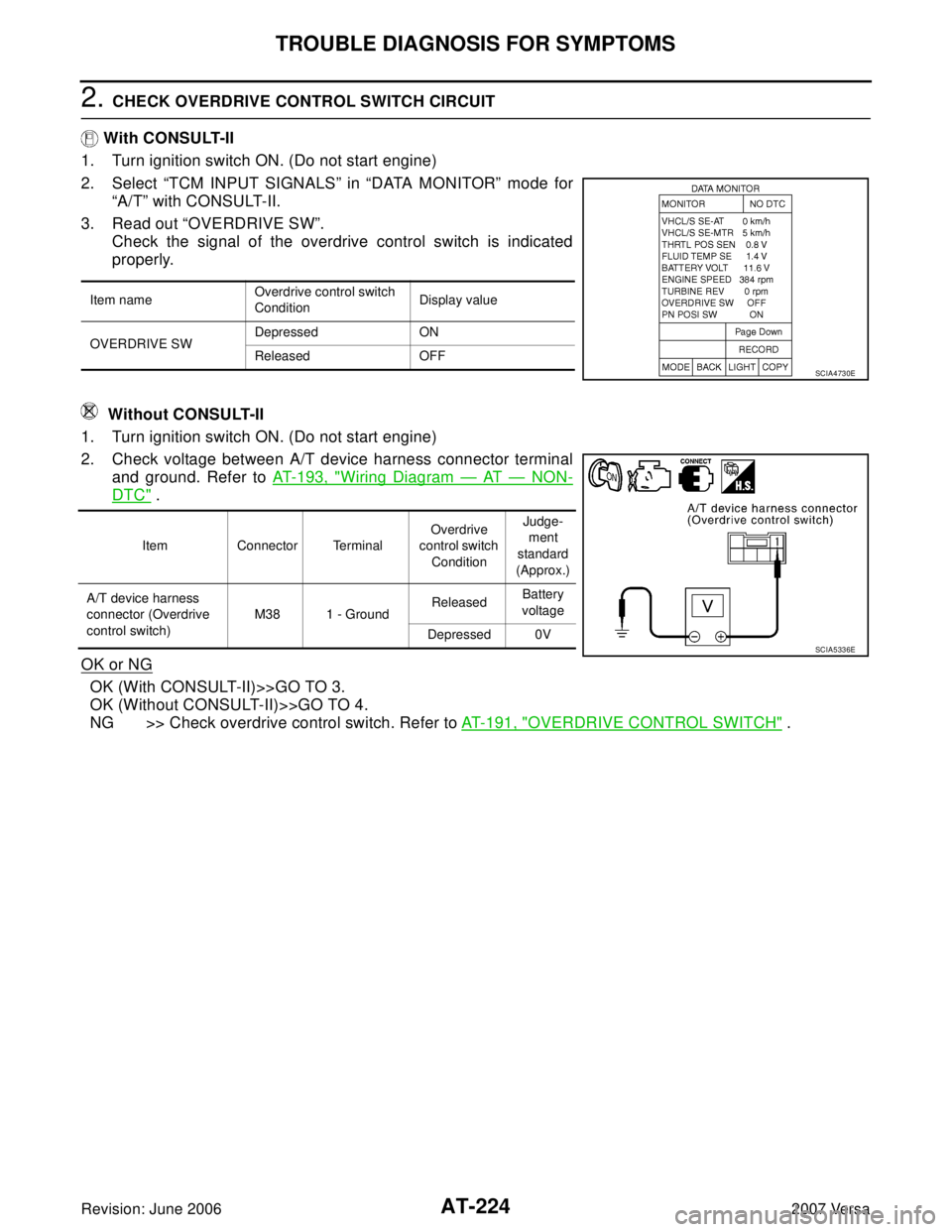
2. CHECK OVERDRIVE CONTROL SWITCH CIRCUIT
With CONSULT-II
1. Turn ignition switch ON. (Do not start engine)
2. Select “TCM INPUT SIGNALS” in “DATA MONITOR” mode for
“A/T” with CONSULT-II.
3. Read out “OVERDRIVE SW”.
Check the signal of the overdrive control switch is indicated
properly.
Without CONSULT-II
1. Turn ignition switch ON. (Do not start engine)
2. Check voltage between A/T device harness connector terminal
and ground. Refer to AT-193, "
Wiring Diagram — AT — NON-
DTC" .
OK or NG
OK (With CONSULT-II)>>GO TO 3.
OK (Without CONSULT-II)>>GO TO 4.
NG >> Check overdrive control switch. Refer to AT-191, "
OVERDRIVE CONTROL SWITCH" .
Item nameOverdrive control switch
ConditionDisplay value
OVERDRIVE SWDepressed ON
Released OFF
SCIA4730E
Item Connector TerminalOverdrive
control switch
ConditionJudge-
ment
standard
(Approx.)
A/T device harness
connector (Overdrive
control switch)M38 1 - GroundReleasedBattery
voltage
Depressed 0V
SCIA5336E