Page 125 of 2896

AT-112
DTC P0720 VEHICLE SPEED SENSOR·A/T (REVOLUTION SENSOR)
Revision: June 20062007 Versa
6. CHECK HARNESS BETWEEN TCM AND REVOLUTION SENSOR (POWER)
1. Turn ignition switch OFF.
2. Disconnect the TCM connector and revolution sensor harness connector.
3. Check continuity between TCM connector terminals and revolu-
tion sensor harness connector terminal. Refer to AT-52, "
Circuit
Diagram" and AT-183, "Wiring Diagram — AT — MAIN" .
4. If OK, check harness for short to ground and short to power.
5. Reinstall any part removed.
OK or NG
OK >> 10A fuse (No.49, located in the IPDM E/R) or ignition switch are malfunctioning.
NG >> Repair open circuit or short to ground or short to power in harness or connectors.
7. CHECK HARNESS BETWEEN TCM AND REVOLUTION SENSOR (SENSOR GROUND)
1. Turn ignition switch OFF.
2. Disconnect the TCM connector and revolution sensor harness connector.
3. Check continuity between TCM connector terminal and revolu-
tion sensor harness connector terminal.
4. If OK, check harness for short to ground and short to power.
5. Reinstall any part removed.
OK or NG
OK >> GO TO 5.
NG >> Repair open circuit or short to ground or short to power
in harness or connectors.
8. CHECK DTC
Perform AT-107, "
DTC Confirmation Procedure" .
OK or NG
OK >>INSPECTION END
NG >> GO TO 5.
Item Connector Terminal Continuity
TCM E31 10
Ye s
Revolution sensor F38 1
TCM E31 19
Ye s
Revolution sensor F38 1
SCIA2617E
Item Connector Terminal Continuity
TCM E32 42
Ye s
Revolution sensor F38 3
SCIA2618E
Page 127 of 2896
AT-114
DTC P0725 ENGINE SPEED SIGNAL
Revision: June 20062007 Versa
Wiring Diagram — AT — ENGSSUCS005O6
BCWA0652E
Page 132 of 2896
DTC P0731 A/T 1ST GEAR FUNCTION
AT-119
D
E
F
G
H
I
J
K
L
MA
B
AT
Revision: June 20062007 Versa
Diagnostic ProcedureUCS005O C
1. CHECK VALVE RESISTANCE
1. Remove control valve assembly. Refer to AT-242, "
Control Valve Assembly and Accumulators" .
–Shift solenoid valve A
–Shift solenoid valve B
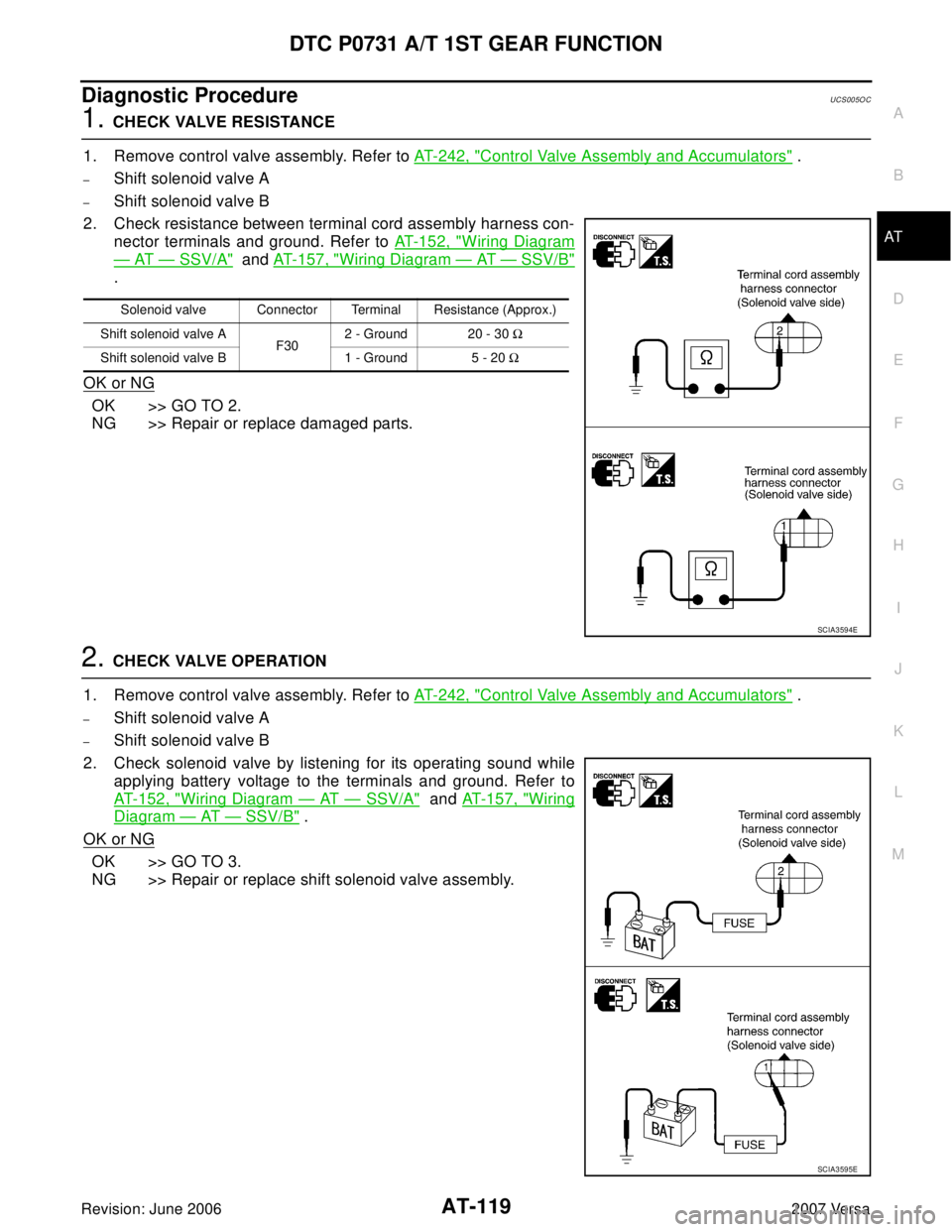
2. Check resistance between terminal cord assembly harness con-
nector terminals and ground. Refer to AT - 1 5 2 , "
Wiring Diagram
— AT — SSV/A" and AT-157, "Wiring Diagram — AT — SSV/B"
.
OK or NG
OK >> GO TO 2.
NG >> Repair or replace damaged parts.
2. CHECK VALVE OPERATION
1. Remove control valve assembly. Refer to AT-242, "
Control Valve Assembly and Accumulators" .
–Shift solenoid valve A
–Shift solenoid valve B
2. Check solenoid valve by listening for its operating sound while
applying battery voltage to the terminals and ground. Refer to
AT-152, "
Wiring Diagram — AT — SSV/A" and AT - 1 5 7 , "Wiring
Diagram — AT — SSV/B" .
OK or NG
OK >> GO TO 3.
NG >> Repair or replace shift solenoid valve assembly.
Solenoid valve Connector Terminal Resistance (Approx.)
Shift solenoid valve A
F302 - Ground 20 - 30 Ω
Shift solenoid valve B 1 - Ground 5 - 20 Ω
SCIA3594E
SCIA3595E
Page 136 of 2896
DTC P0732 A/T 2ND GEAR FUNCTION
AT-123
D
E
F
G
H
I
J
K
L
MA
B
AT
Revision: June 20062007 Versa
Diagnostic ProcedureUCS005O H
1. CHECK VALVE RESISTANCE
1. Remove control valve assembly. Refer to AT-242, "
Control Valve Assembly and Accumulators" .
–Shift solenoid valve B
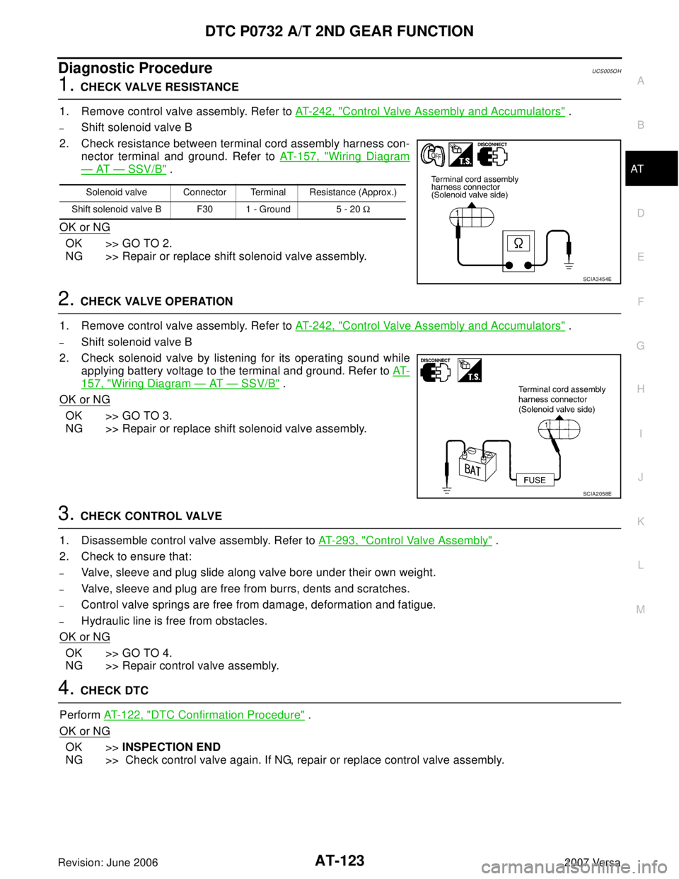
2. Check resistance between terminal cord assembly harness con-
nector terminal and ground. Refer to AT-157, "
Wiring Diagram
— AT — SSV/B" .
OK or NG
OK >> GO TO 2.
NG >> Repair or replace shift solenoid valve assembly.
2. CHECK VALVE OPERATION
1. Remove control valve assembly. Refer to AT-242, "
Control Valve Assembly and Accumulators" .
–Shift solenoid valve B
2. Check solenoid valve by listening for its operating sound while
applying battery voltage to the terminal and ground. Refer to AT-
157, "Wiring Diagram — AT — SSV/B" .
OK or NG
OK >> GO TO 3.
NG >> Repair or replace shift solenoid valve assembly.
3. CHECK CONTROL VALVE
1. Disassemble control valve assembly. Refer to AT-293, "
Control Valve Assembly" .
2. Check to ensure that:
–Valve, sleeve and plug slide along valve bore under their own weight.
–Valve, sleeve and plug are free from burrs, dents and scratches.
–Control valve springs are free from damage, deformation and fatigue.
–Hydraulic line is free from obstacles.
OK or NG
OK >> GO TO 4.
NG >> Repair control valve assembly.
4. CHECK DTC
Perform AT-122, "
DTC Confirmation Procedure" .
OK or NG
OK >>INSPECTION END
NG >> Check control valve again. If NG, repair or replace control valve assembly.
Solenoid valve Connector Terminal Resistance (Approx.)
Shift solenoid valve B F30 1 - Ground 5 - 20 Ω
SCIA3454E
SCIA2058E
Page 139 of 2896
AT-126
DTC P0733 A/T 3RD GEAR FUNCTION
Revision: June 20062007 Versa
Diagnostic ProcedureUCS005OM
1. CHECK VALVE RESISTANCE
1. Remove control valve assembly. Refer to AT-242, "
Control Valve Assembly and Accumulators" .
–Shift solenoid valve A
–Shift solenoid valve B
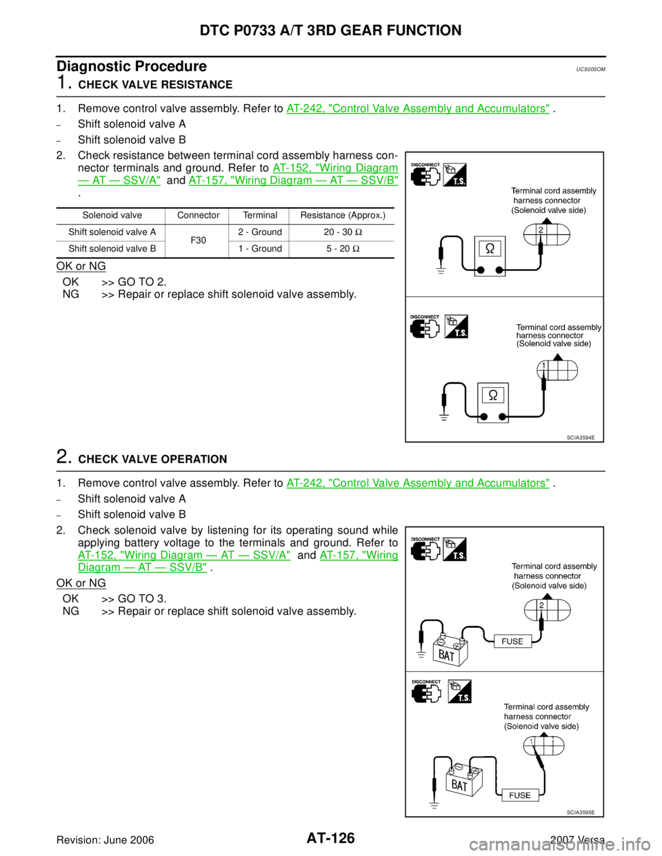
2. Check resistance between terminal cord assembly harness con-
nector terminals and ground. Refer to AT-152, "
Wiring Diagram
— AT — SSV/A" and AT-157, "Wiring Diagram — AT — SSV/B"
.
OK or NG
OK >> GO TO 2.
NG >> Repair or replace shift solenoid valve assembly.
2. CHECK VALVE OPERATION
1. Remove control valve assembly. Refer to AT-242, "
Control Valve Assembly and Accumulators" .
–Shift solenoid valve A
–Shift solenoid valve B
2. Check solenoid valve by listening for its operating sound while
applying battery voltage to the terminals and ground. Refer to
AT-152, "
Wiring Diagram — AT — SSV/A" and AT-157, "Wiring
Diagram — AT — SSV/B" .
OK or NG
OK >> GO TO 3.
NG >> Repair or replace shift solenoid valve assembly.
Solenoid valve Connector Terminal Resistance (Approx.)
Shift solenoid valve A
F302 - Ground 20 - 30 Ω
Shift solenoid valve B 1 - Ground 5 - 20 Ω
SCIA3594E
SCIA3595E
Page 143 of 2896
AT-130
DTC P0734 A/T 4TH GEAR FUNCTION
Revision: June 20062007 Versa
Diagnostic ProcedureUCS005OS
1. CHECK SHIFT-UP (D3 TO D4 )
During AT- 6 1 , "
Cruise Test — Part 1" .
Does A/T shift from D
3 to D4 at the specified speed?
YES >> GO TO 11.
NO >> GO TO 2.
2. CHECK LINE PRESSURE
Perform line pressure test. Refer to AT-56, "
LINE PRESSURE TEST" .
OK or NG
OK >> GO TO 3.
NG >> GO TO 7.
3. CHECK VALVE RESISTANCE
1. Remove control valve assembly. Refer to AT-242, "
Control Valve Assembly and Accumulators" .
–Shift solenoid valve A
–Shift solenoid valve B
2. Check resistance between terminal cord assembly harness con-
nector terminals and ground. Refer to AT-152, "
Wiring Diagram
— AT — SSV/A" and AT-157, "Wiring Diagram — AT — SSV/B"
.
OK or NG
OK >> GO TO 4.
NG >> Replace solenoid valve assembly.
SCIA7190E
Solenoid valve Connector Terminal Resistance (Approx.)
Shift solenoid valve A
F302 - Ground 20 - 30 Ω
Shift solenoid valve B 1 - Ground 5 - 20 Ω
SCIA3594E
Page 144 of 2896
DTC P0734 A/T 4TH GEAR FUNCTION
AT-131
D
E
F
G
H
I
J
K
L
MA
B
AT
Revision: June 20062007 Versa
4. CHECK VALVE OPERATION
1. Remove control valve assembly. Refer to AT-242, "
Control Valve Assembly and Accumulators" .
–Shift solenoid valve A
–Shift solenoid valve B
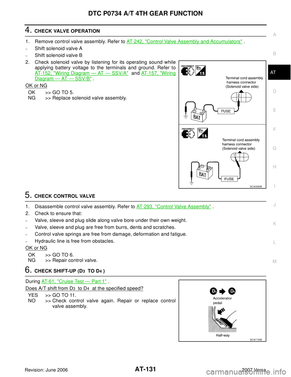
2. Check solenoid valve by listening for its operating sound while
applying battery voltage to the terminals and ground. Refer to
AT-152, "
Wiring Diagram — AT — SSV/A" and AT - 1 5 7 , "Wiring
Diagram — AT — SSV/B" .
OK or NG
OK >> GO TO 5.
NG >> Replace solenoid valve assembly.
5. CHECK CONTROL VALVE
1. Disassemble control valve assembly. Refer to AT-293, "
Control Valve Assembly" .
2. Check to ensure that:
–Valve, sleeve and plug slide along valve bore under their own weight.
–Valve, sleeve and plug are free from burrs, dents and scratches.
–Control valve springs are free from damage, deformation and fatigue.
–Hydraulic line is free from obstacles.
OK or NG
OK >> GO TO 6.
NG >> Repair control valve.
6. CHECK SHIFT-UP (D3 TO D4 )
During AT-61, "
Cruise Test — Part 1" .
Does A/T shift from D
3 to D4 at the specified speed?
YES >> GO TO 11.
NO >> Check control valve again. Repair or replace control
valve assembly.
SCIA3595E
SCIA7190E
Page 145 of 2896
AT-132
DTC P0734 A/T 4TH GEAR FUNCTION
Revision: June 20062007 Versa
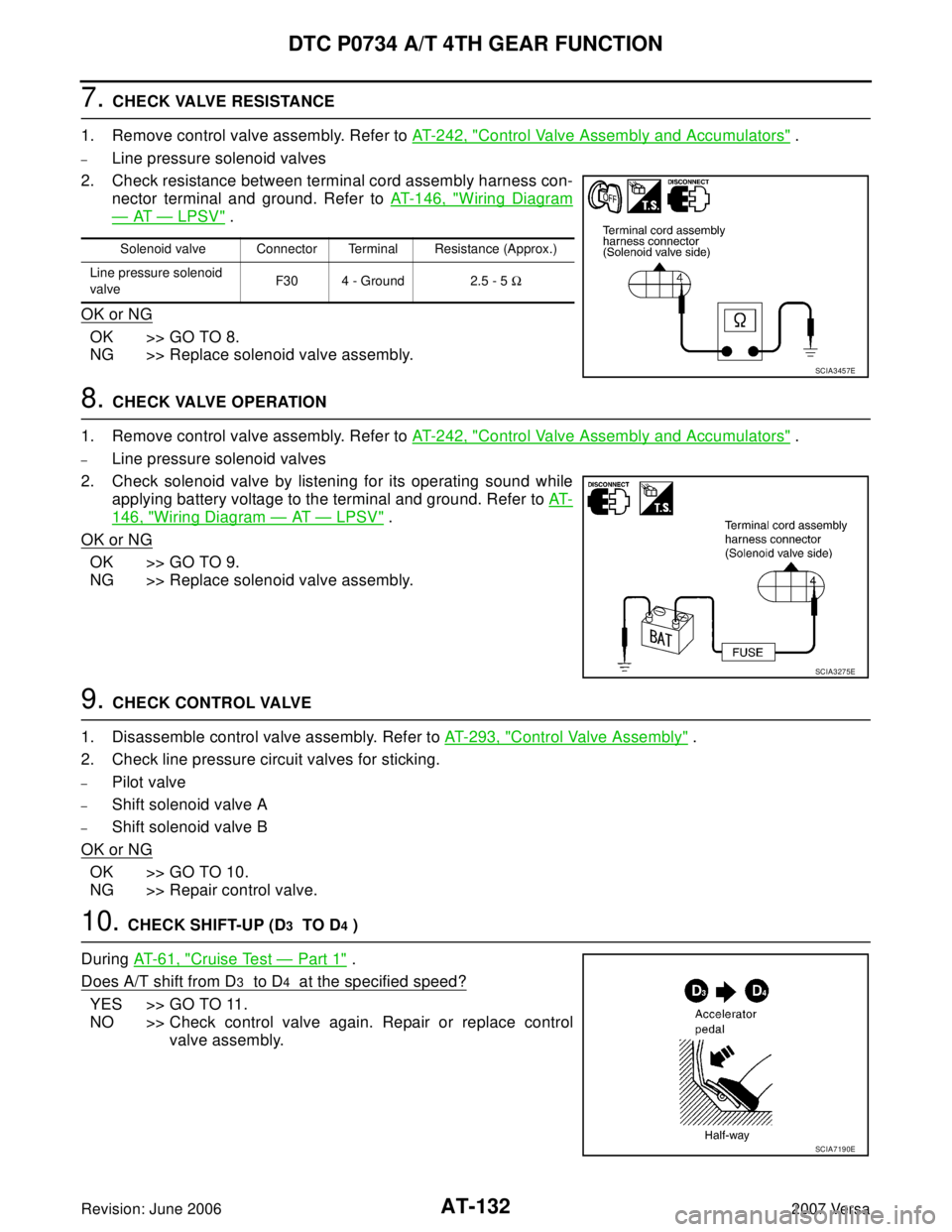
7. CHECK VALVE RESISTANCE
1. Remove control valve assembly. Refer to AT-242, "
Control Valve Assembly and Accumulators" .
–Line pressure solenoid valves
2. Check resistance between terminal cord assembly harness con-
nector terminal and ground. Refer to AT-146, "
Wiring Diagram
— AT — LPSV" .
OK or NG
OK >> GO TO 8.
NG >> Replace solenoid valve assembly.
8. CHECK VALVE OPERATION
1. Remove control valve assembly. Refer to AT-242, "
Control Valve Assembly and Accumulators" .
–Line pressure solenoid valves
2. Check solenoid valve by listening for its operating sound while
applying battery voltage to the terminal and ground. Refer to AT-
146, "Wiring Diagram — AT — LPSV" .
OK or NG
OK >> GO TO 9.
NG >> Replace solenoid valve assembly.
9. CHECK CONTROL VALVE
1. Disassemble control valve assembly. Refer to AT-293, "
Control Valve Assembly" .
2. Check line pressure circuit valves for sticking.
–Pilot valve
–Shift solenoid valve A
–Shift solenoid valve B
OK or NG
OK >> GO TO 10.
NG >> Repair control valve.
10. CHECK SHIFT-UP (D3 TO D4 )
During AT- 6 1 , "
Cruise Test — Part 1" .
Does A/T shift from D
3 to D4 at the specified speed?
YES >> GO TO 11.
NO >> Check control valve again. Repair or replace control
valve assembly.
Solenoid valve Connector Terminal Resistance (Approx.)
Line pressure solenoid
valveF30 4 - Ground 2.5 - 5 Ω
SCIA3457E
SCIA3275E
SCIA7190E