Page 367 of 2896

AT-354
ASSEMBLY
Revision: June 20062007 Versa
ASSEMBLYPFP:00000
Assembly (1)UCS005WG
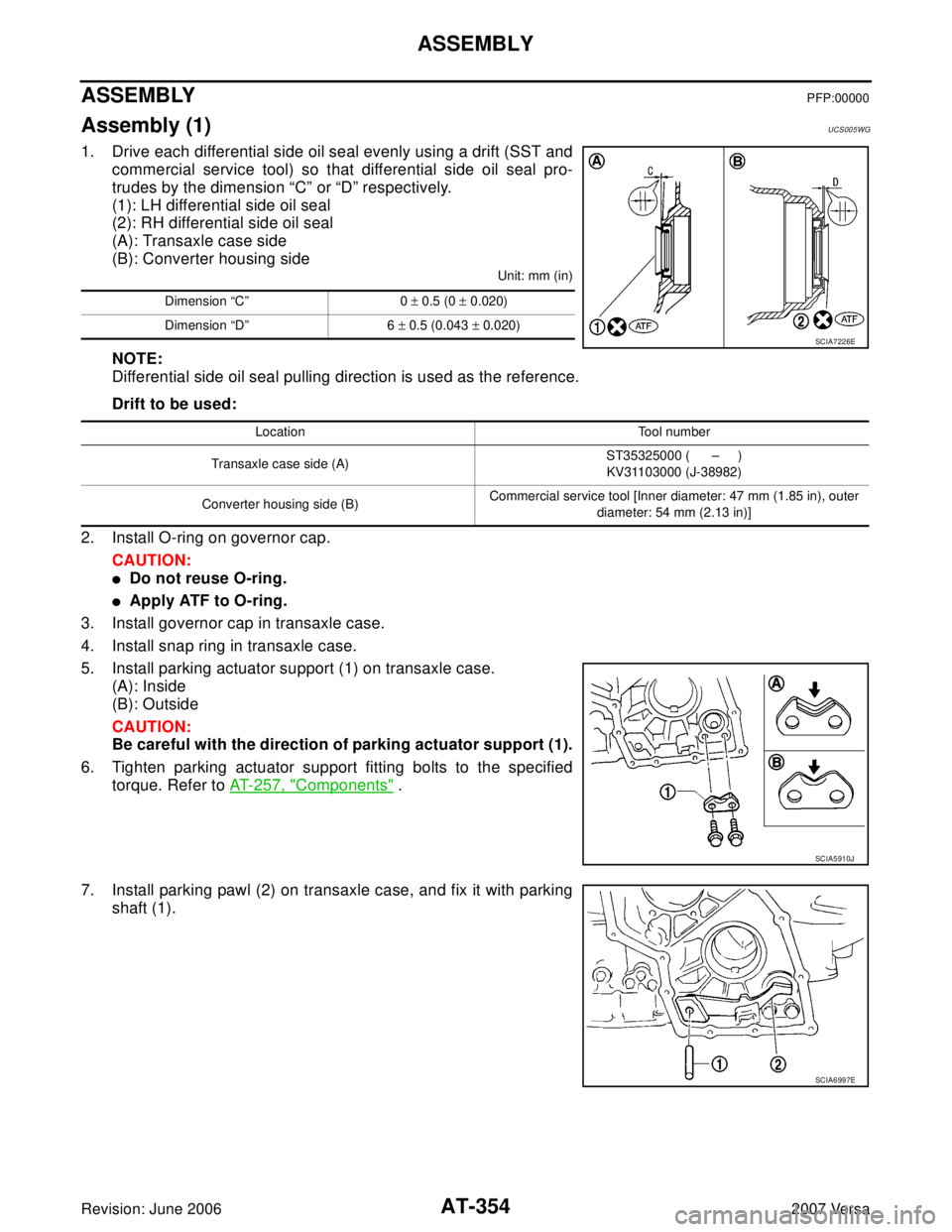
1. Drive each differential side oil seal evenly using a drift (SST and
commercial service tool) so that differential side oil seal pro-
trudes by the dimension “C” or “D” respectively.
(1): LH differential side oil seal
(2): RH differential side oil seal
(A): Transaxle case side
(B): Converter housing side
Unit: mm (in)
NOTE:
Differential side oil seal pulling direction is used as the reference.
Drift to be used:
2. Install O-ring on governor cap.
CAUTION:
�Do not reuse O-ring.
�Apply ATF to O-ring.
3. Install governor cap in transaxle case.
4. Install snap ring in transaxle case.
5. Install parking actuator support (1) on transaxle case.
(A): Inside
(B): Outside
CAUTION:
Be careful with the direction of parking actuator support (1).
6. Tighten parking actuator support fitting bolts to the specified
torque. Refer to AT-257, "
Components" .
7. Install parking pawl (2) on transaxle case, and fix it with parking
shaft (1).
Dimension “C” 0 ± 0.5 (0 ± 0.020)
Dimension “D” 6 ± 0.5 (0.043 ± 0.020)
SCIA7226E
Location Tool number
Transaxle case side (A)ST35325000 ( – )
KV31103000 (J-38982)
Converter housing side (B)Commercial service tool [Inner diameter: 47 mm (1.85 in), outer
diameter: 54 mm (2.13 in)]
SCIA5910J
SCIA6997E
Page 391 of 2896

AT-378
SERVICE DATA AND SPECIFICATIONS (SDS)
Revision: June 20062007 Versa
SERVICE DATA AND SPECIFICATIONS (SDS)PFP:00030
General SpecificationsUCS005WL
*: Refer to MA-11, "RECOMMENDED FLUIDS AND LUBRICANTS" .
Vehicle Speed at Which Gear Shifting OccursUCS005W M
�At half throttle, the accelerator opening is 4/8 of the full opening.
Vehicle Speed at When Lock-up Occurs/ReleasesUCS005WN
Stall SpeedUCS005WO
Line PressureUCS005WP
EngineMR18DE
Automatic transaxle model RE4F03B
Automatic transaxle assembly Model code number 3CX0D
Transaxle gear ratio1st 2.861
2nd 1.562
3rd 1.000
4th 0.697
Reverse 2.310
Final drive 4.072
Recommended fluidGenuine NISSAN Matic D ATF (Continental U.S. and Alaska) or
Canada NISSAN Automatic Transmission Fluid*
Fluid capacity [ (US qt, Imp qt)]7.9 (8-3/8, 7)
Throttle positionVehicle speed km/h (MPH)
D1 → D2D2 → D3D3 → D4D4 → D3D3 → D2D2 → D1
Full throttle51 - 59
(32 - 37)97 - 105
(60 - 65)154 - 162
(96 - 101)150 - 158
(93 - 98)87 - 95
(54 - 59)40 - 48
(25 - 30)
Half throttle34 - 42
(21 - 26)62 - 70
(39 - 43)124 - 132
(77 - 82)69 - 77
(43 - 48)36 - 44
(22 - 27)19 - 27
(12 - 17)
Throttle position Selector lever positionVehicle speed km/h (MPH)
Lock-up ON Lock-up OFF
2.0/8“D” position 86 - 94 (53 - 58) 59 - 67 (37 - 42)
“D” position (OD OFF) 86 - 94 (53 - 58) 83 - 91 (52 - 57)
Stall revolution (rpm)2,300 - 2,750
Engine speedLine pressure kPa (kg/cm
2 , psi)
“D”, “2” and “1” positions “R” position
Idle speed 500 (5.1, 73) 778 (7.9, 113)
Stall speed 1,173 (12.0, 170) 1,825 (18.6, 265)
Page 392 of 2896

SERVICE DATA AND SPECIFICATIONS (SDS)
AT-379
D
E
F
G
H
I
J
K
L
MA
B
AT
Revision: June 20062007 Versa
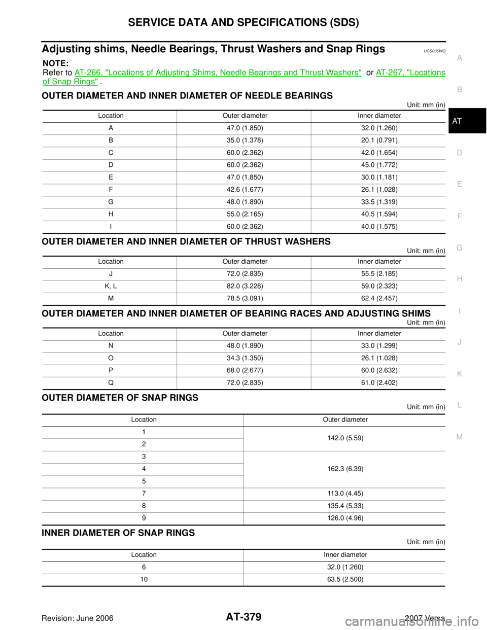
Adjusting shims, Needle Bearings, Thrust Washers and Snap RingsUCS005WQ
NOTE:
Refer to AT-266, "
Locations of Adjusting Shims, Needle Bearings and Thrust Washers" or AT-267, "Locations
of Snap Rings" .
OUTER DIAMETER AND INNER DIAMETER OF NEEDLE BEARINGS
Unit: mm (in)
OUTER DIAMETER AND INNER DIAMETER OF THRUST WASHERS
Unit: mm (in)
OUTER DIAMETER AND INNER DIAMETER OF BEARING RACES AND ADJUSTING SHIMS
Unit: mm (in)
OUTER DIAMETER OF SNAP RINGS
Unit: mm (in)
INNER DIAMETER OF SNAP RINGS
Unit: mm (in) Location Outer diameter Inner diameter
A 47.0 (1.850) 32.0 (1.260)
B 35.0 (1.378) 20.1 (0.791)
C 60.0 (2.362) 42.0 (1.654)
D 60.0 (2.362) 45.0 (1.772)
E 47.0 (1.850) 30.0 (1.181)
F 42.6 (1.677) 26.1 (1.028)
G 48.0 (1.890) 33.5 (1.319)
H 55.0 (2.165) 40.5 (1.594)
I 60.0 (2.362) 40.0 (1.575)
Location Outer diameter Inner diameter
J 72.0 (2.835) 55.5 (2.185)
K, L 82.0 (3.228) 59.0 (2.323)
M 78.5 (3.091) 62.4 (2.457)
Location Outer diameter Inner diameter
N 48.0 (1.890) 33.0 (1.299)
O 34.3 (1.350) 26.1 (1.028)
P 68.0 (2.677) 60.0 (2.632)
Q 72.0 (2.835) 61.0 (2.402)
Location Outer diameter
1
142.0 (5.59)
2
3
162.3 (6.39) 4
5
7 113.0 (4.45)
8 135.4 (5.33)
9 126.0 (4.96)
Location Inner diameter
6 32.0 (1.260)
10 63.5 (2.500)
Page 393 of 2896

AT-380
SERVICE DATA AND SPECIFICATIONS (SDS)
Revision: June 20062007 Versa
Control ValvesUCS005WR
CONTROL VALVE SPRINGS
Unit: mm (in)
AccumulatorUCS005WS
RETURN SPRINGS
Unit: mm (in)
Unit: mm (in)
O-RINGS
Unit: mm (in)
Clutches and BrakesUCS005WT
REVERSE CLUTCH
Location spring designation Free length (l) Outer diameter (D)
Upper bodyL14 Pilot valve spring 38.98 (1.5346) 8.9 (0.350)
L151–2 accumulator valve spring 20.5 (0.807) 6.95 (0.2736)
1–2 accumulator piston spring 55.66 (2.1913) 19.5 (0.768)
L16 1st reducing valve spring 27.0 (1.063) 7.0 (0.276)
L17 3–2 timing valve spring 23.0 (0.906) 6.65 (0.2618)
L18 Overrun clutch reducing valve spring 37.5 (1.476) 7.0 (0.276)
L19 Torque converter relief valve spring 33.3 (1.311) 9.0 (0.354)
L20 Torque converter clutch control valve spring 53.01 (2.0870) 6.5 (0.256)
L21 Cooler check valve spring 28.04 (1.1039) 7.15 (0.2815)
Lower bodyL3 Pressure regulator valve spring 45.0 (1.772) 15.0 (0.591)
L4 Overrun clutch control valve spring 21.7 (0.854) 7.0 (0.276)
L5 Accumulator control valve spring 22.0 (0.866) 6.5 (0.256)
L6 Shift valve A spring 21.7 (0.854) 7.0 (0.276)
L7 Shuttle valve spring 51.0 (2.008) 5.65 (0.2224)
L12 Shift valve B spring 21.7 (0.854) 7.0 (0.276)
L13Pressure modifier valve spring 32.0 (1.260) 6.9 (0.272)
Pressure modifier piston spring 30.5 (1.201) 9.8 (0.386)
— Line pressure relief valve spring 17.02 (0.6701) 8.0 (0.315)
— Torque converter pressure holding spring 9.0 (0.354) 7.3 (0.287)
Location Free length (L1 )
Servo release accumulator 62.8 (2.472)
Location Length (L2 )
N-D accumulator46.5 (1.831)
Location Inner diameter (Small) Inner diameter (Large)
Servo release accumulator 26.9 (1.059) 44.2 (1.740)
N-D accumulator 34.6 (1.362) 39.4 (1.551)
Number of drive plates2
Number of driven plates2
Drive plate thickness [mm (in)]Standard 2.0 (0.079)
Allowable limit 1.8 (0.071)
Driven plate thickness [mm (in)] Standard 2.0 (0.079)
Clearance [mm (in)]Standard 0.5 - 0.8 (0.020 - 0.031)
Allowable limit 1.2 (0.047)
Page 394 of 2896

SERVICE DATA AND SPECIFICATIONS (SDS)
AT-381
D
E
F
G
H
I
J
K
L
MA
B
AT
Revision: June 20062007 Versa
HIGH CLUTCH
FORWARD CLUTCH
OVERRUN CLUTCH
LOW & REVERSE BRAKE
BRAKE BAND
Number of drive plates4
Number of driven plates7 (1
*1 + 6*2 )
Drive plate thickness [mm (in)]Standard 1.6 (0.063)
Allowable limit 1.4 (0.055)
Driven plate thickness [mm (in)] Standard
*1 *2
2.0 (0.079) 1.5 (0.059)
Clearance [mm (in)]Standard 1.4 - 1.8 (0.055 - 0.071)
Allowable limit 2.6 (0.102)
Number of drive plates5
Number of driven plates5
Drive plate thickness [mm (in)]Standard 1.8 (0.071)
Allowable limit 1.6 (0.063)
Driven plate thickness [mm (in)] Standard 2.0 (0.079)
Clearance [mm (in)]Standard 0.45 - 0.85 (0.0177 - 0.0335)
Allowable limit 1.85 (0.0728)
Number of drive plates3
Number of driven plates4
Drive plate thickness [mm (in)]Standard 1.6 (0.063)
Allowable limit 1.4 (0.055)
Driven plate thickness [mm (in)] Standard 2.0 (0.079)
Clearance [mm (in)]Standard 1.0 - 1.4 (0.039 - 0.055)
Allowable limit 2.0 (0.079)
Number of drive plates5
Number of driven plates5
Drive plate thickness [mm (in)]Standard 2.0 (0.079)
Allowable limit 1.8 (0.071)
Driven plate thickness [mm (in)] Standard 2.0 (0.079)
Clearance [mm (in)]Standard 1.4 - 1.8 (0.055 - 0.071)
Allowable limit 2.8 (0.110)
Anchor end pin tightening torque [N·m (kg-m, in-lb)] 4.9 (0.50, 43)
Number of returning revolutions for anchor end pin 2.5
Lock nut tightening torque [N·m (kg-m, ft-lb)] 33.9 (3.5, 25)
Page 395 of 2896

AT-382
SERVICE DATA AND SPECIFICATIONS (SDS)
Revision: June 20062007 Versa
Final DriveUCS005WU
DIFFERENTIAL SIDE GEAR CLEARANCE
BEARING PRELOAD
TURNING TORQUE
Planetary CarrierUCS005WV
Oil PumpUCS005WW
Input ShaftUCS005WX
SEAL RING CLEARANCE
SEAL RING
Unit: mm (in)
Reduction Pinion GearUCS005WY
TURNING TORQUE
Band ServoUCS005WZ
RETURN SPRINGS
Unit: mm (in)
Output ShaftUCS005X0
SEAL RING CLEARANCE
SEAL RING
Unit: mm (in)
END PLAY
Clearance between side gear and differential case with washer [mm (in)] 0.1 - 0.2 (0.004 - 0.008)
Differential side bearing preload mm (in) 0.05 - 0.09 (0.0020 - 0.0035)
Turning torque of final drive assembly N-m (kg-cm, in-lb) 0.68 - 1.26 (7.0 - 13.0, 6.0 - 11.0)
Clearance between planetary carrier and pinion washer [mm (in)]Standard 0.15 - 0.70 (0.0059 - 0.0276)
Allowable limit 0.80 (0.0315)
Oil pump side clearance0.02 - 0.04 (0.0008 - 0.0016)
Clearance between oil pump housing and outer gear [mm (in)]Standard 0.08 - 0.15 (0.0031 - 0.0059)
Allowable limit 0.15 (0.0059)
Oil pump cover seal ring clearance [mm (in)]Standard 0.10 - 0.25 (0.0039 - 0.0098)
Allowable limit 0.25 (0.0098)
Input shaft seal ring clearance [mm (in)]Standard 0.08 - 0.23 (0.0031 - 0.0091)
Allowable limit 0.23 (0.091)
Outer diameter Inner diameter Width
24 (0.94) 20.4 (0.803) 1.97 (0.0776)
Turning torque of reduction pinion gear [N·m (kg-m, in-lb)] 0.11 - 0.69 (0.01 - 0.07, 1 - 6)
Return spring Free length
2nd servo return spring 32.5 (1.280)
OD servo return spring 38.52 (1.5165)
Output shaft seal ring clearance [mm (in)]Standard 0.10 - 0.25 (0.0039 - 0.0098)
Allowable limit 0.25 (0.0098)
Outer diameter Inner diameter Width
29.5 (1.161) 26.2 (1.031) 1.95 (0.0768)
Output shaft end play mm (in) 0 - 0.5 (0 - 0.020)
Page 396 of 2896

SERVICE DATA AND SPECIFICATIONS (SDS)
AT-383
D
E
F
G
H
I
J
K
L
MA
B
AT
Revision: June 20062007 Versa
Bearing RetainerUCS005X1
SEAL RING CLEARANCE
Total End PlayUCS005X2
Reverse Clutch End PlayUCS005X3
Removal and InstallationUCS005X4
Shift Solenoid ValvesUCS005X5
Solenoid ValvesUCS005X6
A/T Fluid Temperature SensorUCS005X7
Remarks: Specification data are reference values.
Revolution SensorUCS005X8
Dropping ResistorUCS005X9
Turbine Revolution Sensor (Power Train Revolution Sensor)UCS005XA
Bearing retainer seal ring clearance [mm (in)]Standard 0.10 - 0.27 (0.0039 - 0.0106)
Allowable limit 0.27 (0.0106)
Total end play [mm (in)] 0.25 - 0.55 (0.0098 - 0.0217)
Reverse clutch end play [mm (in)] 0.65 - 1.0 (0.0256 - 0.039)
Distance between end of converter housing and torque converter [mm (in)] 14.4 (0.567)
Gear position 1 2 3 4
Shift solenoid valve A ON (Closed) OFF (Open) OFF (Open) ON (Closed)
Shift solenoid valve B ON (Closed) ON (Closed) OFF (Open) OFF (Open)
Solenoid valve designation Resistance (Approx.) Terminal
Shift solenoid valve A 20 - 30 Ω2
Shift solenoid valve B 5 - 20 Ω1
Overrun clutch solenoid valve 20 - 30 Ω3
Line pressure solenoid valve 2.5 - 5.0 Ω4
Torque converter clutch solenoid valve 5 - 20 Ω5
Condition Specification (Approx.)
Cold [20°C (68°F)]
↓
Hot [80°C (176°F)]1.5V
↓
0.5V2.5 kΩ
↓
0.3 kΩ
Condition Judgment standard
When driving at 20 km/h (12 MPH) 150 Hz (Approx.)
Resistance12Ω (Approx.)
Condition Judgment standard
When driving at 20 km/h (12 MPH) 360 Hz (Approx.)
Page 397 of 2896
AT-384
SERVICE DATA AND SPECIFICATIONS (SDS)
Revision: June 20062007 Versa